Table of Contents
Advertisement
Available languages
Available languages
Advertisement
Chapters
Table of Contents
Troubleshooting

Related Manuals for MINN KOTA EDGE 30


Summary of Contents for MINN KOTA EDGE 30
- Page 1 EDGE BOW-MOUNT TROLLING MOTOR OWNER'S MANUAL...
- Page 2 THANK YOU Thank you for choosing Minn Kota. We believe that you should spend more time fishing and less time positioning your boat. That’s why we build the smartest, toughest, most intuitive trolling motors on the water. Every aspect of a Minn Kota trolling motor is thought out and rethought until it’s good enough to bear our name.
-
Page 3: Table Of Contents
Table Of CONTeNTs SAFETY CONSIDERATIONS ....................4 WARRANTY ........................5 KNOW YOUR BOAT ......................6 FEATURES ........................7 INSTALLATION ......................... 8 Mount Installation ....................8 BATTERY & WIRING INSTALLATION ..................11 Boat Rigging & Product Installation ................. 11 Conductor Gauge and Circuit Breaker Sizing Table ........... 11 Selecting the Correct the Batteries ................ -
Page 4: Safety Considerations
WARNING You are responsible for the safe and prudent operation of your vessel. We have designed your Minn Kota product to be an accurate and reliable tool that will enhance boat operation and improve your ability to catch fish. This product does not relieve you from the responsibility for safe operation of your boat. -
Page 5: Warranty
Products purchased outside of the U.S. must be returned prepaid with proof of purchase (including the date of purchase and serial number) to any Authorized Minn Kota Service Center in the country of purchase. -
Page 6: Know Your Boat
KNOW YOUR bOaT Port Starboard Inboard Outboard Keel Port Starboard Gunwale Transom Stern Gunwale Stern Hull 6 | minnkotamotors.com ©2019 Johnson Outdoors Marine Electronics, Inc. -
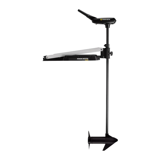
Page 7: Features
feaTURes Tilt/Extend Tiller Adjustable Depth Collar Steering Tension Knob Mounting Bracket Lifetime Warranty Flexible Composite Shaft Cool Quiet Power Motor Propeller NOTICE: Specifications subject to change without notice. This diagram is for reference only and may differ from your actual motor. -
Page 8: Installation
INsTallaTION TOOLS AND RESOURCES REQUIRED • #3 Phillips Screw Driver • 9/32” Drill Bit • A second person to help with • Drill • 7/16” Box End Wrench the installation INSTALLATION MOUNT INSTALLATION Please review the following guidelines before beginning the NOTICE: We recommend that you have another person installation of the Edge:... - Page 9 INSTALLATION Deploy the Motor and remove the Motor Assembly Adjustable from the Mount by loosening the Steering Tension Depth Collar Knob and opening the door. CAUTION Latch & Door Prior to opening this hinge door, relieve mount pressure by pulling on the rope to disengage the mount latch pin. Mount Steering Tension Knob...
- Page 10 INSTALLATION Reinstall the Motor Rest using the six original ¼” Phillips Screws. Reinstall the Motor Assembly into the Mount and securely tighten the Steering Tension Knob. Motor Rest Latch & Door Phillips Screws Phillips Mounting Bracket Screws Steering Adjustable Tension Motor Assembly Depth Collar Knob...
-
Page 11: Battery & Wiring Installation
CAUTION These guidelines apply to general rigging to support your Minn Kota motor. Powering multiple motors or additional electrical devices from the same power circuit may impact the recommended conductor gauge and circuit breaker size. If you are using wire longer than that provided with your unit, follow the conductor gauge and circuit breaker sizing table below. -
Page 12: Selecting The Correct The Batteries
Review your charger’s manual carefully or consult the manufacturer prior to use to ensure your charger is compatible. Minn Kota recommends using Minn Kota brand chargers to recharge the batteries connected to your Minn Kota trolling motor, as they have been engineered to work with motors that include a bonding wire. -
Page 13: Connecting The Batteries
CONNECTING THE BATTERIES Automatic Jump Start Systems and Selector Switches Automatic jump start systems and selector switches tie the negatives of the connected batteries together. Connecting these systems to the “High Side” Battery or “Middle” Battery in a multi-battery system will cause significant damage to your trolling motor and electronics. The only trolling motor battery that is safe to connect to one of these systems is the “Low Side”... -
Page 14: Motor Wiring Diagram
MOTOR WIRING DIaGRaM EDGE The following Motor Wiring Diagram applies to all Edge Hand Control models. Switch White White Yellow Black M- Black B- Red B+ Motor Battery 1 12 Volt Deep Cycle Marine Battery NOTICE: This is a multi-voltage diagram. Double-check your motor's voltage for proper connections. Over-Current Protection Devices are not shown in this illustration. -
Page 15: Using & Adjusting The Motor
UsING & aDJUsTING THe MOTOR MOUNT FEATURES Become familiar with the features of the Motor to maximize the capabilities this product offers. Control Head Motor Shaft Pull Grip and Rope Lower Unit Tube Lock Motor Rest Hold Down Strap • The Motor Mount is designed to fold back and lock the motor flat on the deck when not in use and to provide secure stowage for transport. -
Page 16: Stowing And Deploying The Motor
USING & ADJUSTING THE MOTOR STOWING AND DEPLOYING THE MOTOR WARNING When stowing or deploying the motor, keep fingers clear of all hinge and pivot points and all moving parts. Practice proper ergonomics when stowing and deploying the motor to prevent injury. WARNING Moving the motor creates a variety of pinch points. -
Page 17: Motor Adjustments
ADJUSTING THE DEPTH OF THE MOTOR MOTOR ADJUSTMENTS Adjusting the Depth of the Motor When setting the depth be sure the top of the Motor is submerged at least 12” to avoid churning or agitation of surface water. The propeller must be completely submerged. With the Motor deployed, firmly grasp the Shaft or Control Head and hold it steady. -
Page 18: Controlling Speed & Steering With The Tiller
ADJUSTING THE DEPTH OF THE MOTOR Controlling Speed & Steering with the Tiller This Motor offers 5 forward and 3 reverse speeds. The speed control may be operated in either direction, forward or reverse. Turn the tiller handle counterclockwise from (OFF) to increase reverse speed and clockwise from (OFF) to increase forward speed. -
Page 19: Adjusting The Tilt/Extend Tiller
ADJUSTING THE DEPTH OF THE MOTOR Adjusting the Tilt/Extend Tiller Your trolling motor features 7 usable handle tilt positions: 45°, 30°, and 15° up and down from the 0° (horizontal) position. To use the down positions, you must first press the release button located on the left underside of the pivot handle. Your trolling motor handle also features a unique stow position, that is useful for limiting the amount of space required for storage or travel. -
Page 20: Service & Maintenance
seRVICe & MaINTeNaNCe PROPELLER REPLACEMENT TOOLS AND RESOURCES REQUIRED • 1/2” Open End Wrench • Flat Blade Screwdriver INSTALLATION Disconnect the motor from all sources of power prior to changing the propeller. Drive Pin Armature Shaft Hold the propeller and loosen the Prop Nut with a pliers or a wrench. -
Page 21: General Maintenance
GENERAL MAINTENANCE GENERAL MAINTENANCE • After use, the entire motor should be rinsed with freshwater. This series of motors is not equipped for saltwater exposure. • The composite shaft requires periodic cleaning and lubrication for proper retraction and deployment. A coating of an aqueous based silicone spray will improve operation. -
Page 22: For Further Troubleshooting And Repair
Authorized Service Centers Minn Kota has over 800 authorized service providers in the United States and Canada where you can purchase parts or get your products repaired. Please visit our Authorized Service Center page on our website to locate a service provider in your area. -
Page 23: Compliance Statements
Minn Kota motors are not subject to the disposal regulations EAG-VO (electric devices directive) that implements the WEEE directive. Nevertheless never dispose of your Minn Kota motor in a garbage bin but at the proper place of collection of your local town council. - Page 24 FCC COMPLIANCE This device complies with Part 15 of the FCC rules. Operation is subject to the following two conditions: COMPLIANCE STATEMENTS This device may not cause harmful interference. This device must accept any interference that may be received, including interference that may cause undesired operation. Changes or modifi cations not expressly approved by Johnson Outdoors Marine Electronics, Inc.
-
Page 25: Parts Diagram & Parts List
EDGE - 45 THRUST - 12 VOLT - 45” SHAFT The parts diagram and parts list provides Minn Kota® WEEE compliance disassembly instructions. For more information about where you should dispose of your waste equipment for recycling and recovery and/or your European Union member state requirements, please contact your dealer or distributor from which your product was purchased. - Page 26 PARTS DIAGRAM & PARTS LIST Edge 45 Parts List Assembly Part # Description Quantity 2069286 MOTOR ASSEMBLY 12V F/W 3.25 5SPCO *45LB* 1378121 PROPELLER KIT 3.25 *45LB* 2883460 SEAL & O-RING KIT 3.25 *45LB* 2994838 BAG ASSEMBLY - BOLTS NUTS WASHERS 2993811 LATCH STRAP ASSEMBLY, STD, 45”...
- Page 27 PARTS DIAGRAM & PARTS LIST Item Part # Description Quantity 2303430 SCREW 1/4-20 X 5/8 2264372 LOWER ARM, FW, STD. 2266002 BEARING - NYLINER 3/8” SHAFT 2260503 PIVOT PIN 2263605 LATCH STRAP, STD, 45” 2261902 BRACKET - LATCH 2268602 RIVET 1/8” SS 2262709 SPRING- LATCH PIN 2150405...
- Page 28 PARTS DIAGRAM & PARTS LIST Item Part # Description Quantity 2060298 COVER, CONTROL BOX, TRAXXIS FW 2064028 SWITCH 5 SPEED 2062505 CONTROL BOX, 5 SPD, FW 2062905 STRAIN RELIEF 2303412 SCREW, #6 X 5/8 SS 2990465 GRIP/HANDLE ASSY, 5SPD 2060015 BEARING, HANDLE 2063405 SCREW, #6 PFH SS...
-
Page 29: Notes
NOTes minnkotamotors.com | 29 ©2019 Johnson Outdoors Marine Electronics, Inc. - Page 30 Stop buying new batteries and start taking care of the ones you’ve got. Many chargers can actually damage your battery over time – creating shorter run times and shorter overall life. Digitally controlled Minn Kota chargers are designed to provide the fastest charge that protect and extend battery life.
- Page 31 EDGE MOTEUR DE PÊCHE À LA TRAÎNE MONTÉ SUR ÉTRAVE Manuel du Propriétaire...
- Page 32 à amarrer votre embarcation. C’est pourquoi nous construisons les moteurs de pêche à la traîne les plus intelligents, les plus solides et les plus faciles à utiliser. Chaque aspect d’un moteur de pêche à la traîne Minn Kota est réfléchi et étudié jusqu’à ce qu’il soit digne de porter notre nom.
- Page 33 Table Des MaTIÈRes CONSIGNES DE SÉCURITÉ ....................4 GARANTIE ........................5 CONNAISSEZ VOTRE BATEAU ....................6 CARACTÉRISTIQUES ......................7 INSTALLATION ......................... 8 Installation du support ..................... 8 INSTALLATION DE LA BATTERIE ET DU CÂBLAGE ..............11 Gréement de l’embarcation et installation du produit ..........11 Tableau des dimensions de gabarit des conducteurs et disjoncteurs ......
-
Page 34: Consignes De Sécurité
à la navigation et toujours exercer une veille permanente afin de pouvoir réagir au fur et à mesure que les situations se présentent. Vous devez toujours être prêt à reprendre le contrôle manuel de votre bateau. Apprenez à utiliser votre Minn Kota dans une zone exempte de dangers et d’obstacles. -
Page 35: Garantie
Les articles achetés à l’extérieur des États-Unis doivent être retournés, port payé avec la preuve d’achat (y compris la date d’achat et le numéro de série), à tout centre de service agréé Minn Kota dans le pays de l’achat. Le service au titre de la garantie peut être obtenu en communiquant avec le centre de service agréé... -
Page 36: Connaissez Votre Bateau
CONNaIsseZ VOTRe baTeaU Étrave Bâbord Tribord En-bord Hors-bord Quille Bâbord Tribord Plat-bord Tableau Arrière Stern Plat-bord Étrave Poupe Coque 36 | minnkotamotors.com ©2019 Johnson Outdoors Marine Electronics, Inc. -
Page 37: Caractéristiques
CaRaCTéRIsTIQUes Barre d’inclinaison/d’extension Bague de réglage de la profondeur Bouton de tension du gouvernail Support de montage Arbre composite flexible garanti à vie Moteur silencieux Hélice AVIS : Les spécifications peuvent faire l’objet de modifications sans préavis. Le schéma est fourni aux fins de référence seulement et peut différer de votre moteur actuel. -
Page 38: Installation
INsTallaTION OUTILS ET RESSOURCES NÉCESSAIRES • #3 Tournevis cruciforme • Mèche de 9/32 po (7,14 mm) • Une deuxième personne pour vous aider • Perceuse • Clé polygonale 7/16 po (11,11 mm) avec l’installation INSTALLATION INSTALLATION DU SUPPORT Révisez les directives suivantes avant de commencer AVIS : Nous vous conseillons de vous faire aider d’une l’installation du Edge :... - Page 39 INSTALLATION Déployez le moteur et retirez l’assemblage du moteur Bague de réglage du support en desserrant le bouton de tension du de la profondeur gouvernail et en ouvrant la porte. ATTENTION Loquet et porte Avant d’ouvrir cette porte charnière, réduisez la pression sur le support en tirant sur la corde pour désengager la goupille de verrouillage.
- Page 40 INSTALLATION Réinstallez le repose-moteur en utilisant les six vis cruciformes originales de 1/4 po (6,35 mm). Réinstallez l’ensemble moteur dans le support et fixez solidement le bouton de tension du gouvernail. Repose-moteur Loquet et porte cruciformes Support de cruciformes montage Bouton de Bague de réglage tension du...
-
Page 41: Installation De La Batterie Et Du Câblage
ATTENTION Ces lignes directrices s’appliquent au gréement général pour soutenir le moteur de Minn Kota. L’alimentation de multiples moteurs ou d’autres appareils électriques, à partir du même circuit d’alimentation, peut infl uer sur le gabarit de conducteurs et le dimensionnement des disjoncteurs recommandé. -
Page 42: Comment Sélectionner Les Batteries Adéquates
Utilisation de chargeurs-onduleurs Votre moteur de pêche à la traîne Minn Kota peut être conçu avec un fil de masse interne pour réduire les interférences avec d’autres sonars. La plupart des systèmes de charge alternateurs ne tiennent pas compte de ce fil de masse et connectent les bornes négatives des batteries du moteur de pêche à... - Page 43 INSTALLATION DE LA BATTERIE ET DU CâBLAGE électrique étant donné que les interférences provenant du propulseur électrique sont inévitables. Lorsque vous connectez un accessoire supplémentaire à l’une des batteries du propulseur électrique, ou lorsque vous effectuez des connexions entre les batteries du propulseur électrique et d’autres systèmes de batterie sur le bateau, assurez-vous de respecter attentivement les indications ci-dessous.
-
Page 44: Schéma De Câblage Du Moteur
sCHéMa De CâblaGe DU MOTeUR EDGE Le schéma de câblage de moteur suivant s’applique à tous les modèles de commande manuelle Edge. Interrupteur Blanc Blanc Jaune Noir M- Noir B- Rouge B+ Moteur Batterie 1 Batterie Marine À Décharge Profonde 12 Volt AVIS : Il s’agit d’un schéma multitension. -
Page 45: Utilisation Et Réglage Du Moteur
UTIlIsaTION eT RéGlaGe DU MOTeUR CARACTÉRISTIQUES DU SUPPORT Prenez connaissance des fonctionnalités du moteur afin de maximiser les capacités qu’offre ce produit. Tête de Contrôle Poignée et corde Arbre du moteur de traction Verrouillage Unité inférieure du tube Repose-moteur Courroie de retenue •... -
Page 46: Arrimage Et Déploiement Du Moteur
UTILISATION ET RÉGLAGE DU MOTEUR ARRIMAGE ET DÉPLOIEMENT DU MOTEUR AVERTISSEMENT Lorsque vous remontez ou abaissez le moteur, gardez vos doigts loin de toutes charnières et tous points de pivot ainsi que de toutes pièces mobiles. Utilisez de bonnes pratiques ergonomiques lorsque vous arrimez et déployez le moteur afin de prévenir les blessures. AVERTISSEMENT Déplacer le moteur crée une variété... -
Page 47: Ajustements Du Moteur
UTILISATION ET RÉGLAGE DU MOTEUR AJUSTEMENTS DU MOTEUR Réglage de la profondeur du moteur Au moment du réglage de la profondeur, assurez-vous que le dessus du moteur est immergé à au moins 12 po (30,5 cm) afin d’éviter de faire tourbillonner ou d’agiter l’eau à la surface. L’hélice doit être complètement submergée. Une fois le moteur en position immergée, saisissez l’arbre ou la tête de contrôle et maintenez-le/la fermement. -
Page 48: Contrôle De La Vitesse Et De La Direction Avec La Barre
UTILISATION ET RÉGLAGE DU MOTEUR Contrôle de la vitesse et de la direction avec la barre Ce moteur offre 5 vitesses en marche avant et 3 vitesses en marche arrière. Le contrôle de vitesse s’opère dans les deux sens, en marche avant ou arrière. Tournez la poignée de la barre dans le sens antihoraire d’arrêt (OFF), pour augmenter la vitesse en marche arrière et dans le sens horaire d’arrêt (OFF) pour augmenter la vitesse en marche avant. -
Page 49: Réglage De La Barre D'inclinaison/D'extension
UTILISATION ET RÉGLAGE DU MOTEUR Réglage de la barre d’inclinaison/d’extension Votre moteur de pêche à la traîne dispose d’une poignée permettant 7 positions d’inclinaison : De 45°, 30° et 15° vers le haut et le bas à partir de la position (horizontale) de 0°. Pour utiliser les positions vers le bas, vous devez tout d’abord appuyer sur le bouton de déverrouillage situé... -
Page 50: Service Et Entretien
seRVICe eT eNTReTIeN REMPLACEMENT DE L’HÉLICE OUTILS ET RESSOURCES NÉCESSAIRES • Clé ouverte 1/2 po (12,7 mm) • Tournevis à lame plate INSTALLATION Débrancher le moteur de toute source d’alimentation Arbre avant de changer l’hélice. Armature Ergot d’Entraînement Maintenez l’hélice et desserrez l’écrou de l’hélice à l’aide d’une pince ou d’une clé. -
Page 51: Entretien Général
SERVICE ET ENTRETIEN ENTRETIEN GÉNÉRAL • Après l’utilisation, il faut rincer complètement le moteur avec de l’eau douce. Cette série de moteurs ne peut pas être exposée à l’eau salée. • L’arbre en composite doit être régulièrement nettoyé et lubrifié pour une bonne rétraction et un bon déploiement. Une vaporisation de silicone à... -
Page 52: Pour D'autres Services De Dépannage Et De Réparation
Foire aux questions Notre site Web met à votre disposition des FAQ visant à répondre à toutes vos questions au sujet des produits Minn Kota. Veuillez visiter le site Web minnkotamotors.com, puis cliquer sur « Foire aux questions » pour trouver réponse à vos questions. -
Page 53: Déclarations De Conformité
Les moteurs Minn Kota ne sont pas soumis à la réglementation concernant l’élimination VGE-VO (directive pour les dispositifs électriques), qui transpose la directive DEEE. Néanmoins, ne jamais jeter le moteur Minn Kota dans une poubelle, mais plutôt à l’endroit approprié où s’effectue la collecte, recommandé par le conseil municipal local. - Page 54 DÉCLARATIONS DE CONFORMITÉ CONFORMITÉ FCC Cet appareil est conforme à la section 15 des règles de la FCC. Son fonctionnement est soumis aux deux conditions suivantes : Ce dispositif ne doit pas causer d’interférences nuisibles. Cet appareil doit accepter toute interférence qui peut être reçue, y compris les interférences susceptibles de perturber son fonctionnement.
-
Page 55: Schéma Des Pièces Et Liste Des Pièces
EDGE - POUSSÉE DE 45 LB (20,4 KG) – 12 VOLTS – ARBRE DE 45 PO (114 CM) Ce schéma des pièces et cette liste des pièces fournissent les directives pour la dépose de Minn Kota D en conformité avec la directive DEEE. - Page 56 SCHÉMA DES PIÈCES ET LISTE DES PIÈCES Liste des pièces du Edge 45 Ensemble Nº de Pièce Description Quantité 2069286 MOTOR ASSEMBLY 12V F/W 3.25 5SPCO *45LB* 1378121 PROPELLER KIT 3.25 *45LB* 2883460 SEAL & O-RING KIT 3.25 *45LB* 2994838 BAG ASSEMBLY - BOLTS NUTS WASHERS 2993811 LATCH STRAP ASSEMBLY, STD, 45”...
- Page 57 SCHÉMA DES PIÈCES ET LISTE DES PIÈCES Nº d’Article Nº de Pièce Description Quantité 2303430 SCREW 1/4-20 X 5/8 2264372 LOWER ARM, FW, STD. 2266002 BEARING - NYLINER 3/8” SHAFT 2260503 PIVOT PIN 2263605 LATCH STRAP, STD, 45” 2261902 BRACKET - LATCH 2268602 RIVET 1/8”...
- Page 58 SCHÉMA DES PIÈCES ET LISTE DES PIÈCES Nº d’Article Nº de Pièce Description Quantité 2060298 COVER, CONTROL BOX, TRAXXIS FW 2064028 SWITCH 5 SPEED 2062505 CONTROL BOX, 5 SPD, FW 2062905 STRAIN RELIEF 2303412 SCREW, #6 X 5/8 SS 2990465 GRIP/HANDLE ASSY, 5SPD 2060015 BEARING, HANDLE...
-
Page 59: Remarques
ReMaRQUes minnkotamotors.com | 59 ©2019 Johnson Outdoors Marine Electronics, Inc. - Page 60 à la longue, pouvant entraîner une autonomie réduite et une durée de vie plus courte. Les chargeurs Minn Kota à commande numérique assurent une charge rapide pour une protection et une durée de vie prolongée.
Need help?
Do you have a question about the EDGE 30 and is the answer not in the manual?
Questions and answers