Table of Contents
Advertisement
Quick Links
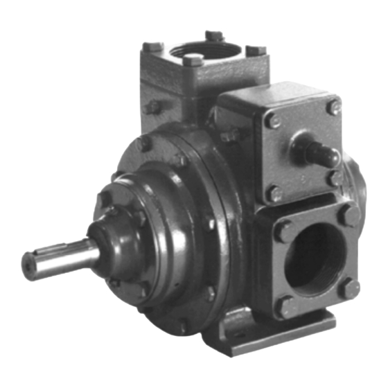
BLACKMER POWER PUMPS
INSTALLATION OPERATION AND MAINTENANCE INSTRUCTIONS
TABLE OF CONTENTS
Technical Data .................................................... 2
Initial Pump Start Up Information ......................... 2
Pre-Installation Cleaning ..................................... 3
Location and Piping ............................................. 3
Mounting ............................................................. 3
Coupling Alignment ............................................. 4
Pump Rotation..................................................... 4
To Change Pump Rotation .................................. 4
Check Valves ...................................................... 4
Pre-Start Up Check List ....................................... 5
Start Up Procedures ............................................ 5
Running the Pump in Reverse Rotation .............. 5
Flushing the Pump .............................................. 6
Pump Relief Valve ............................................... 6
Relief Valve Setting and Adjustment ................... 6
Lubrication .............................................................. 7
Strainers ................................................................. 7
Vane Replacement ................................................. 8
Pump Disassembly ................................................ 8
Parts Replacement ................................................. 8
Pump Assembly ..................................................... 9
TROUBLE SHOOTING ............................................... 10
NOTE: Numbers in parentheses following individual parts
indicate reference numbers on Blackmer Parts Lists
1701-B01 and 1701-B02.
Blackmer pump manuals and parts lists may be obtained
from Blackmer's website (www.blackmer.com) or by
contacting Blackmer Customer Service.
MODELS: TXU1.5, XU2A
Discontinued Model XU2
UL® Listed
Page
960246
INSTRUCTIONS NO. 1701-B00
SAFETY DATA
This is a SAFETY ALERT SYMBOL.
When you see this symbol on the product, or in the
manual, look for one of the following signal words and be
alert to the potential for personal injury, death or major
property damage
Warns of hazards that WILL cause serious personal injury,
death or major property damage.
Warns of hazards that CAN cause serious personal injury,
death or major property damage.
Warns of hazards that CAN cause personal injury
or property damage.
NOTICE:
Indicates special instructions which are very
important and must be followed.
NOTICE:
Blackmer Pumps MUST only be installed in systems,
which have been designed by qualified engineering
personnel. The system MUST conform to all applicable
local and national regulations and safety standards.
This manual is intended to assist in the installation and
operation of the Blackmer power pumps, and MUST be
kept with the pump.
Pump service shall be performed by qualified technicians
ONLY. Service shall conform to all applicable local and
national regulations and safety standards.
Thoroughly review this manual, all instructions and hazard
warnings, BEFORE performing any work on the pump.
Maintain ALL system and pump operation and hazard
warning decals.
Section
1701
Effective
Jan 2014
Replaces
Aug 2010
Advertisement
Table of Contents

Subscribe to Our Youtube Channel
Related Manuals for BLACKMER XU2A


Summary of Contents for BLACKMER XU2A
-
Page 1: Table Of Contents
MAINTENANCE Lubrication .............. 7 This manual is intended to assist in the installation and Strainers ..............7 operation of the Blackmer power pumps, and MUST be Vane Replacement ..........8 kept with the pump. Pump Disassembly ..........8 Parts Replacement ..........8 Pump service shall be performed by qualified technicians Pump Assembly ............. -
Page 2: Pump Data
A pump Identification tag, containing the pump serial number, I.D. number, and model designation, is attached to each pump. It is recommended that the data from this tag be recorded and filed for future reference. If replacement parts are needed, or if information pertaining to the pump is required, this data must be furnished to a Blackmer representative. TECHNICAL DATA INITIAL PUMP START UP INFORMATION 1.5”... -
Page 3: Installation
INSTALLATION NOTICE: Install pressure gauges in the NPT ports provided in the Blackmer pumps must only be installed in systems pump casing to check pump at start up. designed by qualified engineering personnel per NFPA 30 ALL piping and fittings MUST be properly supported to or 30A. -
Page 4: Coupling Alignment
INSTALLATION COUPLING ALIGNMENT PUMP ROTATION The pump must be directly coupled to a gear and/or driver A right-hand pump rotates clockwise with the intake and relief with a flexible coupling. Both angular and parallel coupling valve on the right side, when viewed from the driven end. alignment MUST be maintained between the pump, gear, A left-hand pump rotates counterclockwise with the intake and motor, etc. -
Page 5: Operation
OPERATION Failure to relieve system pressure prior Operation without guards in place can to performing pump service or cause serious personal injury, major maintenance can cause personal injury property damage, or death. or property damage. Hazardous pressure Do not operate can cause personal without guard injury or property... -
Page 6: Flushing The Pump
A system pressure control valve is also recommended when cap. operating for extended periods (more than 1 minute) against Refer to the individual Blackmer pump parts lists for various a closed discharge valve. spring pressure ranges. Unless specified otherwise, pumps are supplied from the factory with the relief valve adjusted to the mid-point of the spring range. -
Page 7: Maintenance
MAINTENANCE NOTICE: Maintenance shall be performed by qualified technicians only. Follow the appropriate procedures and warnings Failure to disconnect and lockout as presented in this manual. electrical power or engine drive before attempting maintenance can cause severe personal injury or death Hazardous SCHEDULED MAINTENANCE machinery can... -
Page 8: Vane Replacement
MAINTENANCE VANE REPLACEMENT 6. Slide the head off the shaft. The head O-ring (72), bearing (24), and mechanical seal (153) will come off with the head NOTICE: assembly. Remove and discard the head O-ring. Maintenance shall be performed by qualified technicians Pull the bearing (24) from the housing in the head. -
Page 9: Pump Assembly
MAINTENANCE PUMP ASSEMBLY Install the remaining vanes into the top positions of the rotor. Rotate the shaft by hand to engage the Before reassembling the pump, inspect all component drive tangs of the mechanical seal jacket in the parts for wear or damage, and replace as required. Wash rotor slots. -
Page 10: Troubleshooting
TROUBLESHOOTING NOTICE: Maintenance shall be performed by qualified technicians only. Follow the appropriate procedures and warnings as presented in this manual. SYMPTOM PROBABLE CAUSE Pump Not Priming Pump not wetted. Worn vanes Suction valve closed. Air leaks in the suction line. Strainer clogged. - Page 11 NOTES 1701-B00 Page 11/12...
- Page 12 Accessories Dispensing, Transfer, In-line Gear Reducers, Bypass Valves, Strainers Visit www.blackmer.com for complete information on all Blackmer products 1809 Century Avenue, Grand Rapids, Michigan 49503-1530 U.S.A. Telephone: (616) 241-1611 • Fax: (616) 241-3752 E-mail: blackmer@blackmer.com • Internet Address: www .blackmer.com...
Need help?
Do you have a question about the XU2A and is the answer not in the manual?
Questions and answers