Table of Contents
Advertisement
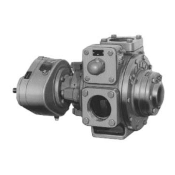
BLACKMER POWER PUMPS
INSTALLATION OPERATION AND MAINTENANCE INSTRUCTIONS
MODELS: GX2B, GX2.5B, GX3E, GX4B,
X2B, X2.5B, X3E, X4B, XH2B, XH2.5B, XH3E, XH4B
TABLE OF CONTENTS
Technical Data .................................................... 2
Initial Pump Start Up Information ........................ 2
Pre-Installation Cleaning ..................................... 3
Location and Piping ............................................. 3
Mounting ............................................................. 3
Coupling Alignment ............................................. 4
Gear Reducer Alignment - GX Models ............... 4
Pump Rotation .................................................... 4
To Change Pump Rotation .................................. 4
Check Valves ...................................................... 4
Pre-Start Up Check List ....................................... 5
Start Up Procedures ............................................ 5
Running the Pump in Reverse Rotation .............. 6
Flushing the Pump .............................................. 6
Pump Relief Valve ............................................... 6
Relief Valve Setting and Adjustment ................... 6
PUMP MAINTENANCE
Lubrication ............................................................. 7
Strainers ................................................................. 7
Vane Replacement ................................................. 8
Pump Disassembly ................................................ 8
Parts Replacement ................................................. 8
Pump Assembly ..................................................... 9
Gear Reducer Lubrication .................................... 11
Oil Seal Replacement .......................................... 12
Gear Reducer Disassembly ................................. 12
Gear Reducer Assembly ...................................... 12
PUMP TROUBLE SHOOTING .................................... 13
GEAR REDUCER TROUBLE SHOOTING .................. 14
NOTE: Numbers in parentheses following individual parts
indicate reference numbers on Blackmer Parts Lists.
Blackmer pump manuals and parts lists may be obtained
from Blackmer's website (www.blackmer.com) or by
contacting Blackmer Customer Service.
PUMP
PUMP PARTS LIST
MODEL
2"
GX
101-B01
101-B02
X
101-B05
101-B06
XH
101-B15
101-B16
Page
2.5"
3"
4"
101-B03
101-B04
101-B07
101-B08
101-B17
101-B18
961222
INSTRUCTIONS NO. 101-B00
SAFETY DATA
This is a SAFETY ALERT SYMBOL.
When you see this symbol on the product, or in the
manual, look for one of the following signal words and be
alert to the potential for personal injury, death or major
property damage
Warns of hazards that WILL cause serious personal injury,
death or major property damage.
Warns of hazards that CAN cause serious personal injury,
death or major property damage.
Warns of hazards that CAN cause personal injury
or property damage.
NOTICE:
Indicates special instructions which are very
important and must be followed.
NOTICE:
Blackmer Pumps MUST only be installed in systems,
which have been designed by qualified engineering
personnel. The system MUST conform to all applicable
local and national regulations and safety standards.
This manual is intended to assist in the installation and
operation of the Blackmer power pumps, and MUST be
kept with the pump.
Pump service shall be performed by qualified technicians
ONLY. Service shall conform to all applicable local and
national regulations and safety standards.
Thoroughly review this manual, all instructions and hazard
warnings, BEFORE performing any work on the pump.
Maintain ALL system and pump operation and hazard
warning decals.
Section
101
Effective
Oct 2015
Replaces
Jun 2015
Advertisement
Table of Contents

Subscribe to Our Youtube Channel
Related Manuals for BLACKMER GX2B


Summary of Contents for BLACKMER GX2B
-
Page 1: Table Of Contents
Pump Disassembly ..........8 Parts Replacement ..........8 This manual is intended to assist in the installation and Pump Assembly ............. 9 operation of the Blackmer power pumps, and MUST be GEAR REDUCER MAINTENANCE kept with the pump. Gear Reducer Lubrication ........11 Oil Seal Replacement .......... -
Page 2: Pump Data
A pump Identification tag, containing the pump serial number, I.D. number, and model designation, is attached to each pump. It is recommended that the data from this tag be recorded and filed for future reference. If replacement parts are needed, or if information pertaining to the pump is required, this data must be furnished to a Blackmer representative. TECHNICAL DATA INITIAL PUMP START UP INFORMATION 2”, 2.5”... -
Page 3: Installation
INSTALLATION NOTICE: ALL piping and fittings MUST be properly supported to Blackmer pumps must only be installed in systems prevent any piping loads from being placed on the pump. designed by qualified engineering personnel. System Check alignment of pipes to pump to avoid strains which design must conform with all applicable regulations and might later cause misalignment. -
Page 4: Coupling Alignment
If necessary, tap it lightly with a soft faced mallet. When aligning the reducer, verify the alignment of the coupling halves as indicated in “Coupling Alignment” section. NOTICE: To determine maximum variation of gear reducer shaft alignment, refer to Blackmer GX model dimension pages 101-B00 Page 4/16... -
Page 5: Operation
Record pressures in the ‘Initial Start Up Information’ section. NOTICE: Blackmer gear reducers are not lubricated at the factory. 3. Check for leakage from the piping and equipment. Oil MUST be added before initial pump start-up 4. Check for overheating, excessive noise or vibration of the 4. -
Page 6: Running The Pump In Reverse Rotation
Reattach the R/V cap gasket and PUMP RELIEF VALVE cap. Refer to the individual Blackmer pump parts lists for various NOTICE: spring pressure ranges. Unless specified otherwise, pumps The pump internal relief valve is designed to protect the... -
Page 7: Lubrication
Hazardous or toxic fluids can cause mechanical seals can cause seal failure. serious injury. If equipped with a Blackmer gear reducer, refer to the ‘Gear Reducer Lubrication’ section of this manual. Operation without guards in place can STRAINERS cause serious personal injury, major Strainers must be cleaned regularly to avoid pump starvation. -
Page 8: Vane Replacement
6. X2.5, XH2.5, X3 and XH3 pump models are equipped VANE REPLACEMENT with locknuts (24A) and lockwashers (24B). To remove: NOTICE: a. Bend up the engaged lockwasher tang and rotate the Maintenance shall be performed by qualified technicians locknut counterclockwise to remove it from the shaft. only. -
Page 9: Pump Assembly
9. Apply a thin coating of quality O-ring lubricant on the PUMP ASSEMBLY inboard shaft to aid installation. Install the inboard head, Before reassembling the pump, inspect all component mechanical seal, and bearing as instructed in steps 2 parts for wear or damage, and replace as required. Wash through 6. - Page 10 12. LOCK COLLAR INSTALLATION – X4, XH4 Models NOTICE: The relief valve setting MUST be tested and adjusted Slide the lock collar (24A) over the shaft and against more precisely before putting the pump into service. the bearing (24), with the counterbored side towards Refer to "Relief Valve Setting and Adjustment"...
-
Page 11: Gear Reducer Maintenance
NOTICE: Hazardous voltage. Blackmer gear reducers are not lubricated at the factory. Can shock, burn or cause death. Oil MUST be added before initial pump start up. Horsepower calculations for Blackmer reducers are based on 75°F (24°C) ambient air temperature;... -
Page 12: Oil Seal Replacement
OIL SEAL REPLACEMENT 5. The pinion and input shaft (102) is a one-piece assembly and does not come apart. If required, remove the NOTICE: bearings (24, 24A) from the shaft with a bearing puller or Follow all hazard warnings and instructions provided in arbor press. -
Page 13: Pump Troubleshooting
11. Grease the outer edge of a new oil seal (104 or 104A) 14. On HRO-GX reducer models, install the remaining two and press the flat side of the seal into the inside face of cover capscrews (112A); torque to 30 lbs ft (40.6 Nm) the closure plate (114). -
Page 14: Gear Reducer Troubleshooting
Excessive overloading. Check horsepower requirements. Worn or damaged gear teeth. Misalignment of pump or motor. Refer to “Gear Reducer Alignment” section of this manual, and Blackmer GX model Dimensions 101-105 – 101-108 for maximum variation of shaft alignment. 101-B00 Page 14/16... - Page 15 NOTES 101-B00 Page 15/16...
- Page 16 Liquefied Gas Transfer, Boosting, Vapor Recovery Hand Operated Pumps Accessories Dispensing, Transfer, In-line Gear Reducers, Bypass Valves, Strainers Visit www.blackmer.com for complete information on all Blackmer products : " " 1528, ." " 3, e .5 : 02/ 973 27 67, e-mail: o ce_bg@opwmarket.com...
Need help?
Do you have a question about the GX2B and is the answer not in the manual?
Questions and answers