Table of Contents
Advertisement
Quick Links
BLACKMER POWER PUMPS
INSTALLATION OPERATION AND MAINTENANCE INSTRUCTIONS
MODELS: SGL1.25A, SGRL1.25A, SGL1.5A
DISCONTINUED MODELS: SGL1.25, SGRL1.25, SGL1.5
TABLE OF CONTENTS
Technical Data ...................................................... 2
Initial Pump Start Up Information ........................... 2
Pre-Installation Cleaning ....................................... 3
Location and Piping ............................................... 3
Pump Relief Valve and Bypass valve .................... 3
Check Valves ........................................................ 4
Mounting ............................................................... 4
Coupling Alignment ............................................... 4
Pump Rotation....................................................... 4
To Change Pump Rotation .................................... 4
Pre-Start Up Check List ......................................... 5
Start Up Procedures .............................................. 5
Relief Valve Setting and Adjustment ..................... 5
Strainers ................................................................... 6
Lubrication ................................................................ 6
Vane Replacement ................................................... 7
Pump Disassembly .................................................. 7
Parts Replacement ................................................... 7
Pump Assembly ....................................................... 8
TROUBLE SHOOTING ................................................. 10
NOTE: Numbers in parentheses following individual parts
indicate reference numbers on Blackmer Parts List No.
801-A01.
Blackmer pump manuals and parts lists may be obtained
from Blackmer's website (www.blackmer.com) or by
contacting Blackmer Customer Service.
This is a SAFETY ALERT SYMBOL.
When you see this symbol on the product, or in the manual,
look for one of the following signal words and be alert to the
potential for personal injury, death or major property damage
Warns of hazards that WILL cause serious personal injury,
Warns of hazards that CAN cause serious personal injury,
Page
Warns of hazards that CAN cause personal injury
Indicates special instructions which are very
Blackmer liquefied gas pumps MUST only be installed
in systems which have been designed by qualified
engineering personnel. The system MUST conform to
all applicable local and national regulations and safety
standards.
This manual is intended to assist in the installation and
operation of the Blackmer liquefied gas pumps, and
MUST be kept with the pump.
Blackmer liquefied gas pump service shall be
performed by qualified technicians ONLY. Service shall
conform to all applicable local and national regulations
and safety standards.
Thoroughly review this manual, all Instructions and
hazard warnings, BEFORE performing any work on the
Blackmer liquefied gas pumps.
Maintain ALL system and Blackmer liquefied gas pump
operation and hazard warning decals.
962325
INSTRUCTIONS NO. 801-A00
Section
Effective
Replaces
SAFETY DATA
death or major property damage.
death or major property damage.
or property damage.
NOTICE:
important and must be followed.
NOTICE:
801
Jan 2019
Jan 2014
Advertisement
Table of Contents

Related Manuals for BLACKMER SGL1.25A


Summary of Contents for BLACKMER SGL1.25A
-
Page 1: Table Of Contents
BEFORE performing any work on the 801-A01. Blackmer liquefied gas pumps. Blackmer pump manuals and parts lists may be obtained Maintain ALL system and Blackmer liquefied gas pump from Blackmer's website (www.blackmer.com) or by operation and hazard warning decals. -
Page 2: Pump Data
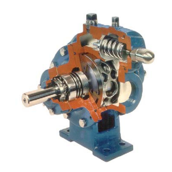
A pump Identification tag, containing the pump serial number, I.D. number, and model designation, is attached to each pump. It is recommended that the data from this tag be recorded and filed for future reference. If replacement parts are needed, or if information pertaining to the pump is required, this data must be furnished to a Blackmer representative. TECHNICAL DATA INITIAL PUMP START UP INFORMATION Model No.: ____________________________________... -
Page 3: Installation
INSTALLATION NOTICE: Check alignment of pipes to pump to avoid strains which Blackmer pumps must only be installed in systems might later cause misalignment. See Figure 2. Unbolt designed by qualified engineering personnel. System flanges or break union joints. Pipes should not spring design must conform with all applicable regulations and away or drop down. -
Page 4: Check Valves
INSTALLATION CHECK VALVES COUPLING ALIGNMENT The use of check valves or foot valves in the supply tank is The pump must be directly coupled to a gear reducer and/or not recommended with self-priming, positive displacement driver with a flexible coupling. Verify coupling alignment after pumps. -
Page 5: Operation
(counterclockwise). Replace the valve cap. SLOWLY build pressure in the pump. Refer to the individual Blackmer pump parts lists for various Start the pump. Priming should occur within one minute. spring pressure ranges. -
Page 6: Maintenance
MAINTENANCE Failure to disconnect and lockout Failure to disconnect and lockout electrical power before attempting electrical power before attempting maintenance can cause shock, burns maintenance can cause shock, burns or or death death Hazardous Hazardous voltage. machinery can Can shock, burn or cause serious cause death. -
Page 7: Vane Replacement
MAINTENANCE VANE REPLACEMENT 5. To remove locknuts and lockwashers (24A and 24B): NOTICE: a. Bend up the engaged lockwasher tang and rotate the Maintenance shall be performed by qualified technicians locknut counterclockwise to remove it from the shaft only. Follow the appropriate procedures and warnings b. -
Page 8: Pump Assembly
MAINTENANCE PUMP ASSEMBLY b. If the pump is equipped with the four-vane rotor and shaft (13A), hold the two bottom vanes (14) in place Before reassembling the pump, inspect all component while inserting the two push rods (77). parts for wear or damage, and replace as required. Wash out the bearing/seal recess of the head and remove any c. - Page 9 MAINTENANCE 17. Attach a new bearing cover gasket (26) and the inboard bearing cover (27) to the inboard head (20). Install the outboard bearing cover (27A) and a new gasket to the outboard head. Make sure the grease fittings (76) on the bearing covers are accessible.
-
Page 10: Troubleshooting
TROUBLESHOOTING NOTICE: Maintenance shall be performed by qualified technicians only. Follow the appropriate procedures and warnings as presented in this manual. SYMPTOM PROBABLE CAUSE 1. Pump not wetted. Pump Not Priming 2. Worn vanes. 3. Internal control valve closed. 4. Strainer clogged. 5. - Page 11 TROUBLESHOOTING … continued Mechanical Seal Leakage 1. O-rings not compatible with the liquids pumped. 2. O-rings nicked, cut or twisted. 3. Shaft at seal area damaged, worn or dirty. 4. Ball bearings overgreased. 5. Excessive cavitation. 6. Mechanical seal faces cracked, scratched, pitted or dirty. 1.
- Page 12 Accessories Dispensing, Transfer, In-line Gear Reducers, Bypass Valves, Strainers Visit www.blackmer.com for complete information on all Blackmer products 1809 Century Avenue, Grand Rapids, Michigan 49503-1530 U.S.A. Telephone: (616) 241-1611 • Fax: (616) 241-3752 E-mail: blackmer@blackmer.com • Internet Address: www .blackmer.com...
Need help?
Do you have a question about the SGL1.25A and is the answer not in the manual?
Questions and answers