Table of Contents
Advertisement
Quick Links
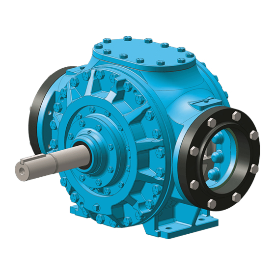
BLACKMER POWER PUMPS
INSTALLATION OPERATION AND MAINTENANCE INSTRUCTIONS
Technical Data ....................................................... 2
Initial Pump Start Up Information ........................... 2
Pre-Installation Cleaning ........................................ 3
Location and Piping ............................................... 3
Pump Mounting ...................................................... 3
Coupling Alignment ................................................ 4
Pump Rotation ....................................................... 4
To Change Pump Rotation .................................... 4
Check Valves ......................................................... 4
Pre-Start Up Check List ......................................... 5
Start Up Procedures .............................................. 5
Running the Pump in Reverse Rotation ................ 5
Flushing the Pump ................................................. 6
Relief Valve Setting and Adjustment ..................... 6
Torque Table ......................................................... 7
Scheduled Maintenance ........................................ 7
Strainers .......................................................... 7
Lubrication ....................................................... 7
Pump Disassembly ................................................ 8
Seal/Bearing Replacement .................................... 8
Complete Pump Disassembly .............................. 10
Pump Assembly ................................................... 11
TROUBLE SHOOTING ................................................. 14
Numbers in parentheses following individual parts
indicate reference numbers on the Blackmer CRL8A
Parts List 701-D01.
Blackmer pump manuals and parts lists may be obtained
from Blackmer's website (www.blackmer.com) or by
contacting Blackmer Customer Service.
MODELS: CRL8A
SAFETY DATA
This is a SAFETY ALERT SYMBOL.
When you see this symbol on the product, or in the
manual, look for one of the following signal words and be
alert to the potential for personal injury, death or major
property damage
Warns of hazards that WILL cause serious personal
injury, death or major property damage.
Warns of hazards that CAN cause serious personal
injury, death or major property damage.
Warns of hazards that CAN cause personal injury
or property damage.
NOTICE:
Indicates special instructions which are very
important and must be followed.
NOTICE:
Blackmer Power Pumps MUST only be installed in
systems, which have been designed by qualified
engineering personnel. The system MUST conform to all
applicable local and national regulations and safety
standards.
This manual is intended to assist in the installation and
operation of Blackmer Power pumps, and MUST be kept
with the pump.
Pump service shall be performed by qualified technicians
ONLY. Service shall conform to all applicable local and
national regulations and safety standards.
Thoroughly review this manual, all instructions and
hazard warnings, BEFORE performing any work on the
pump.
Maintain ALL system and pump operation and hazard
warning decals.
960253
INSTRUCTIONS NO. 701-D00
Section
701
Effective
Mar 2016
Replaces
Jan 2014
Advertisement
Table of Contents

Subscribe to Our Youtube Channel
Related Manuals for BLACKMER CRL8A


Summary of Contents for BLACKMER CRL8A
-
Page 1: Table Of Contents
Flushing the Pump ..........6 Relief Valve Setting and Adjustment ..... 6 This manual is intended to assist in the installation and MAINTENANCE operation of Blackmer Power pumps, and MUST be kept Torque Table ............7 with the pump. Scheduled Maintenance ........7 Strainers ............ -
Page 2: Pump Data
If replacement parts are needed, or if information pertaining to the pump is required, this data must be furnished to a Blackmer representative. TECHNICAL DATA *... -
Page 3: Installation
INSTALLATION NOTICE: Expansion joints, placed at least 36" (0.9m) from the Blackmer power pumps must only be installed in pump, will compensate for expansion and contraction of systems designed by qualified engineering personnel. the pipes. Contact the flexible connector/hose System design must conform with all applicable... -
Page 4: Coupling Alignment
INSTALLATION COUPLING ALIGNMENT TO CHANGE PUMP ROTATION The pump must be directly coupled to a gear and/or driver To change pump rotation the pump must be disassembled with a flexible coupling. Verify coupling alignment after and the liner (41), vanes (14) and pump mounted relief valve installation of new or rebuilt pumps. -
Page 5: Operation
OPERATION STARTUP PROCEDURES NOTICE: Operation without guards in place can Consult the "General Pump Troubleshooting" section of cause serious personal injury, major this manual if difficulties during start up are experienced. property damage, or death. SLOWLY build pressure in the pump. Do not operate without guard Start the motor. -
Page 6: Flushing The Pump
Replace the valve cap. Refer to the individual Blackmer pump parts lists for various spring pressure ranges. Unless specified otherwise, pumps are supplied from the factory with the relief valve adjusted to the mid-point of the spring range. -
Page 7: Maintenance
MAINTENANCE TORQUE TABLE Capscrew Torque Values Bearing Failure to disconnect and lockout Head Cover electrical power before attempting 178 lbs-ft. 50 lbs-ft. 50 lbs-ft. maintenance can cause shock, burns or CRL8 (241 Nm) (68 Nm) (68 Nm) death Hazardous voltage. Can shock, burn or cause death. -
Page 8: Pump Disassembly
MAINTENANCE PUMP DISASSEMBLY Bend up the engaged lockwasher tang and tighten the locknut (24A) on outboard end until shaft cannot be rotated by hand. This will ensure proper rotor/shaft (13) NOTICE: alignment during reassembly. Follow all hazard warnings and instructions provided in the “Maintenance”... - Page 9 MAINTENANCE 10. Inspect shaft sleeve (154A). If replacement is 16. Install carbon rotating face (153F) and O-ring (153L) over necessary, remove capscrews (155), set aside. If shaft sleeve (154A) while aligning drive notches in necessary, use seal mounting holes as jackscrew holes carbon with drive pins in seal rotating assembly.
-
Page 10: Complete Pump Disassembly
MAINTENANCE VANE REPLACEMENT AND/OR a. Pull the bearing (24) and grease seal carrier assembly (104B, 104A and 104C) from the housing in COMPLETE PUMP DISASSEMBLY the hub. NOTICE: b. If worn or damaged, remove the grease seal (104A) Follow all hazard warnings and instructions provided in from the carrier (104B). -
Page 11: Pump Assembly
MAINTENANCE COMPLETE PUMP ASSEMBLY Remove the vanes (14) and push rods (77) from the rotor and shaft assembly. Inspect for wear and damage, and Before reassembling the pump, inspect all component replace as follows: parts for wear or damage, and replace as required. Wash Insert the three push rods (77) into the rotor. - Page 12 MAINTENANCE 13. Place small amount of Loctite # 220 onto seal mounting capscrews (153J). Install into corresponding threaded holes on seal sleeve. Torque capscrews to 20 inlbf (2.25 Nm). 14. Lightly lubricate inner O-ring (153L) on carbon rotating face using bearing grease identified in this manual. Take care to keep seal face free from grease.
- Page 13 MAINTENANCE: 28. LOCKNUT ADJUSTMENT It is important that the bearing locknuts (24A) and lockwashers (24B) be installed and adjusted properly. Overtightened locknuts can cause bearing failure or a broken lockwasher tang. Loose locknuts will allow the Operation without guards in place can rotor to shift against the discs, causing wear.
-
Page 14: Troubleshooting
TROUBLESHOOTING NOTICE: Maintenance shall be performed by qualified technicians only, following the appropriate procedures and warnings as presented in this manual. SYMPTOM PROBABLE CAUSE Pump not wetted. Worn vanes. Suction valve closed. Internal control valve closed. Strainer clogged. Suction line or valves clogged or too restrictive. Pump Not Priming Broken drive train. - Page 15 TROUBLESHOOTING NOTICE: Maintenance shall be performed by qualified technicians only, following the appropriate procedures and warnings as presented in this manual. SYMPTOM PROBABLE CAUSE Foreign objects entering the pump. Running the pump dry for extended periods of time. Cavitation. Incompatibility with the liquids pumped. Damaged Vanes Excessive heat.
- Page 16 1809 Century Avenue, Grand Rapids, Michigan 49503-1530 U.S.A. Telephone: (616) 241-1611 • Fax: (616) 241-3752 701-D00 page 16/16...
Need help?
Do you have a question about the CRL8A and is the answer not in the manual?
Questions and answers