Table of Contents
Advertisement
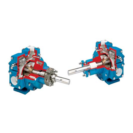
BLACKMER POWER PUMPS
INSTALLATION OPERATION AND MAINTENANCE INSTRUCTIONS
MODELS: NP1.5B, NP2F, NP2.5F, NP3F, NP4F, NPH4F
TABLE OF CONTENTS
NOTE: Numbers in parentheses following individual parts
indicate reference numbers on Blackmer Parts Lists.
Blackmer pump manuals and parts lists may be obtained
from Blackmer's website (www.blackmer.com) or by
contacting Blackmer Customer Service.
NP1.5
103-A01
103-A02
NP3
103-A04
103-A05
Page
1 - 2
NP2
NP2.5
103-A03
NP4
NPH4
103-A06
SAFETY DATA
This is a SAFETY ALERT SYMBOL.
When you see this symbol on the product, or in the
manual, look for one of the following signal words and be
alert to the potential for personal injury, death or major
Warns of hazards that WILL cause serious personal injury,
2
2
Warns of hazards that CAN cause serious personal injury,
3
3
3
4
Warns of hazards that CAN cause personal injury
4
4
4
4
Indicates special instructions which are very
5
5
5
6
6
6
Blackmer Pumps MUST only be installed in systems,
which have been designed by qualified engineering
7
personnel. The system MUST conform to all applicable
7
local and national regulations and safety standards.
7
8
This manual is intended to assist in the installation and
8
operation of the Blackmer NP Series pumps, and MUST
10
be kept with the pump.
11
Pump service shall be performed by qualified technicians
ONLY. Service shall conform to all applicable local and
national regulations and safety standards.
Thoroughly review this manual, all instructions and hazard
warnings, BEFORE performing any work on the pump.
Maintain ALL system and pump operation and hazard
warning decals.
960052
INSTRUCTIONS 103-A00
Section
Effective
Replaces
property damage
death or major property damage.
death or major property damage.
or property damage.
NOTICE:
important and must be followed.
NOTICE:
103
Oct 2012
Oct 2011
Advertisement
Table of Contents

Subscribe to Our Youtube Channel
Related Manuals for BLACKMER NP1.5B


Summary of Contents for BLACKMER NP1.5B
-
Page 1: Table Of Contents
Vane Replacement Pump Disassembly This manual is intended to assist in the installation and Pump Assembly operation of the Blackmer NP Series pumps, and MUST TROUBLE SHOOTING be kept with the pump. AFFF PUMPS Pump service shall be performed by qualified technicians ONLY. -
Page 2: Pump Data
If replacement parts are needed, or if information pertaining to the pump is required, this data must be furnished to a Blackmer representative. TABLE 1 – TECHNICAL DATA INITIAL PUMP START UP INFORMATION 1.5”, 2”, 2.5”, 3”... -
Page 3: Installation
INSTALLATION NOTICE: ALL piping and fittings MUST be properly supported to Blackmer pumps must only be installed in systems prevent any piping loads from being placed on the designed by qualified engineering personnel. System pump. design must conform with all applicable regulations and Check alignment of pipes to pump to avoid strains codes and provide warning of all system hazards. -
Page 4: Coupling Alignment
INSTALLATION HEATING HEADS / JACKETS COUPLING ALIGNMENT NOTICE: The pump must be directly coupled to a gear and/or driver Maximum recommended heating jacket steam pressure with a flexible coupling. Verify coupling alignment after is 150 PSI (10.3 bar). installation of new or rebuilt pumps. Both angular and parallel coupling alignment MUST be maintained between the pump, Jacketed heads are recommended for heating highly gear, motor, etc. -
Page 5: Operation
Installation, Operation and Instruction Manual. performance level. NOTICE: Blackmer gear reducers are not lubricated at the factory. Oil must be added before initial pump start up. Check the entire pumping system to verify that the proper inlet and discharge valves are fully open, and that the drain valves and other auxiliary valves are closed. -
Page 6: Flushing The Pump
(see table 1). Refer to the individual Blackmer pump parts lists for various spring pressure ranges. Unless specified otherwise, pumps are supplied from the factory with the relief valve adjusted to the mid-point of the spring range. -
Page 7: Maintenance
Sleeve bearings (bushings) are lubricated by the liquid being maintenance can cause personal injury pumped. Additional lubrication is not required. or property damage. IF EQUIPPED: Blackmer gear reducers are shipped from Hazardous pressure can cause personal the factory without oil in the gearcase. Fill with the grade of... -
Page 8: Pump Disassembly
MAINTENANCE PUMP DISASSEMBLY 2. Reassemble the OUTBOARD side of the pump first: NOTICE: For a CLOCKWISE rotation pump, position the pump Follow all hazard warnings and instructions provided in cylinder with the INTAKE port to the left. the “Maintenance” section of this manual. ... - Page 9 MAINTENANCE While the liquid is being pumped, check for leakage from the stuffing box. If necessary, STOP the pump and uniformly tighten the packing follower stud nuts (18) 1/4 turn at a time to reduce leakage. Restart the pump and check the stuffing box temperature several minutes after each adjustment for signs of overheating.
-
Page 10: Trouble Shooting
PUMP TROUBLESHOOTING NOTICE: Maintenance shall be performed by qualified technicians only, following the appropriate procedures and warnings as presented in this manual. SYMPTOM PROBABLE CAUSE Pump Not Priming 1. Pump not wetted. 2. Suction valve closed. 3. Air leaks in the suction line. 4. -
Page 11: Afff Pumps
NOTICE: An electrical time clock is recommended to record Blackmer NP pumps are not approved for use in systems elapsed operating time. Refer to the ‘Scheduled where automatic system pressure balance exceeds 200 Maintenance - Pump’... - Page 12 Stainless Steel Sliding Vane Pumps Sliding Vane Pumps: 5 to 2200 GPM 1 to 265 GPM: Acids, Brines, Sugars, Syrups, Re ned Fuels, Lique ed Gases, Solvents,Process Beer, Beet Juice, Cider, Flavor Extracts, etc. ® System One Centrifugal Pumps Magnetic Drive Pumps 10 to 7500 GPM;...
Need help?
Do you have a question about the NP1.5B and is the answer not in the manual?
Questions and answers