Table of Contents
Advertisement
Quick Links
BLACKMER POWER PUMPS
INSTALLATION OPERATION AND MAINTENANCE INSTRUCTIONS
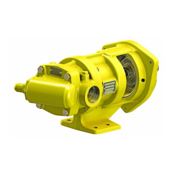
ProVane
Patent Protected by U.S. Patents 7134855 & 7316551 B2 and Related Foreign Patents.
TABLE OF CONTENTS
General Safety Data ................................................1-2
Initial Pump Start Up Information ................................ 2
Technical Data ........................................................... 2
Pre-Installation Cleaning ............................................ 3
Location and Piping .................................................... 3
Mounting .................................................................... 4
Coupling Alignment .................................................... 4
Pump Rotation............................................................ 4
To Reverse Pump Rotation ........................................ 4
Check Valves ............................................................. 4
Pre-Start Up Check List .............................................. 5
Start Up Procedures ................................................... 5
Running the Pump in Reverse .................................... 5
Flushing the Pump ..................................................... 6
Optional Pump Relief Valve........................................ 6
Optional Relief Valve Setting and Adjustment ............ 7
Torque Table ................................................................. 8
Lubrication ..................................................................... 8
Strainers ........................................................................ 8
Vane Replacement ........................................................ 8
Pump Disassembly ....................................................... 9
Parts Replacement ........................................................ 9
Pump Assembly .......................................................... 10
TROUBLE SHOOTING ...................................................... 13
This is a SAFETY ALERT SYMBOL.
When you see this symbol on the product, or in the manual,
look for one of the following signal words and be alert to the
potential for personal injury, death or major property damage
Warns of hazards that WILL cause serious personal injury,
death or major property damage.
Warns of hazards that CAN cause serious personal injury,
death or major property damage.
Warns of hazards that CAN cause personal injury
or property damage.
NOTICE:
Indicates special instructions which are very
important and must be followed.
®
Models: PV6B, 8B
Page
SAFETY DATA
ONLY Pump models listed below are covered in this Manual
Cylinder Type Models
PV6B, PV8B
Blackmer manuals and parts lists may be obtained from
Blackmer's website (www.blackmer.com) or by contacting
Blackmer Customer Service.
Numbers in parentheses following individual parts indicate
reference numbers on Blackmer Part Lists.
NOTICE:
Blackmer Pumps MUST only be installed in systems, which
have been designed by qualified engineering personnel. The
system MUST conform to all applicable local and national
regulations and safety standards.
This manual is intended to assist in the installation and
operation of the Blackmer ProVane pumps, and MUST be
kept with the pump.
Pump service shall be performed by qualified technicians
ONLY.
Service shall conform to all applicable local and
national regulations and safety standards.
Thoroughly review this manual, all instructions and hazard
warnings, BEFORE performing any work on the pump.
Maintain ALL system and pump operation and hazard
warning decals.
965820
Page 1/16
INSTRUCTIONS NO. 111-B00
Section
111
Effective
Feb 2013
Replaces
Dec 2007
Material
Parts List
Ductile Iron
111-B01
Advertisement
Table of Contents

Subscribe to Our Youtube Channel
Related Manuals for BLACKMER ProVane PV6B


Summary of Contents for BLACKMER ProVane PV6B
-
Page 1: Table Of Contents
Initial Pump Start Up Information ........ 2 PV6B, PV8B Ductile Iron 111-B01 Technical Data ............2 Blackmer manuals and parts lists may be obtained from INSTALLATION Blackmer's website (www.blackmer.com) or by contacting Pre-Installation Cleaning ..........3 Blackmer Customer Service. Location and Piping ............ 3 Mounting .............. -
Page 2: Pump Data
A pump Identification tag, containing the pump serial number, I.D. number, and model designation, is attached to each pump. It is recommended that the data from this tag be recorded and filed for future reference. If replacement parts are needed, or if information pertaining to the pump is required, this data must be furnished to a Blackmer representative. TECHNICAL DATA... -
Page 3: Installation
NOTICE: flanges or break union joints. Pipes must not spring Blackmer ProVane pumps may or may not be fitted with away or drop down. After pump has been in operation an internal relief valve. If an internal relief valve is not for a week or two, completely recheck alignment. -
Page 4: Mounting
INSTALLATION PUMP MOUNTING PUMP ROTATION A solid foundation reduces noise and vibration, and will PV6,8 pumps will ALWAYS operate in the clockwise rotation improve pump performance. On permanent installations it is when viewed from the driven end. See Figures 4 and 5. recommended the pumping unit be secured by anchor bolts as shown in Figure 2. -
Page 5: Operation
OPERATION PRE-START UP CHECK LIST Check the alignment of the pipes to the pump. Pipes must be supported so that they do not spring away or Operation without guards in place can drop down when pump flanges or union joints are cause serious personal injury, major disconnected. -
Page 6: Flushing The Pump
Blackmer ProVane pumps may or may not be fitted with an internal relief valve. If an internal relief valve is not supplied, an external bypass valve must be used. The pump’s internal relief valve is designed to protect only the pump from excessive pressure and must not be used as a system pressure control valve. -
Page 7: Optional Relief Valve Setting And Adjustment
Reattach R/V cap O-ring and RV cap. Hazardous pressure can cause personal Refer to the individual Blackmer pump parts lists for various injury or property damage spring pressure ranges. Unless specified otherwise, pumps are supplied from the factory with the relief valve adjusted to the mid-point of the spring range. -
Page 8: Torque Table 1
The head LUBRICATION O-ring should come off with the head assembly. The Blackmer ProVane pumps are equipped with 3. Turn the shaft by hand until a worn vane comes to the top ball bearings that require no additional lubrication. -
Page 9: Pump Disassembly
MAINTENANCE: PUMP DISASSEMBLY 12. Only disassemble rotor & shaft if necessary for part replacement. Disassemble the rotor (13B) and shaft NOTICE: (13A) by removing the six cap-screws (13C). See figure Follow all hazard warnings and instructions provided in the “Maintenance” section of this manual. NOTE: The numbers in parentheses following individual parts indicate reference numbers on the Pump Parts List. -
Page 10: Pump Assembly
MAINTENANCE: PUMP ASSEMBLY FLOW DIRECTION OPTIONS Before reassembling the pump, inspect all component NO vane or rotational changes are required to reverse parts for wear or damage, and replace as required. Wash flow direction for the PV6, 8. The pump will have a out the bearing/seal recess of the head and remove any CLOCKWISE ROTATION regardless of flow direction. - Page 11 MAINTENANCE: PUSHROD INSTALLATION Install Stationary Seal Elements Mechanical Seal type 9, 16 a. Apply a small amount of lubricant in the seal access of PUSHROD the bearing adjuster (188) b. Install a new stationary seat and O-ring into the bearing adjuster until fully bottomed out. Type 9 only - align slot in stationary seat with anti- rotation pin (25A) in bearing adjuster (188) before inserting stationary seat.
- Page 12 MAINTENANCE: 14. LOCKNUT ADJUSTMENT 19. Carefully install the head (23) into the cylinder. If pump It is important that the bearing locknut (24A) and lock is equipped with internal relief valve, orient the relief washer (24B) be installed and adjusted properly. Over valve per instruction in PUMP RELIEF VALVE section tightening the locknut can cause bearing failure or a of this manual.
-
Page 13: Trouble Shooting
GENERAL PUMP TROUBLESHOOTING NOTICE: Maintenance shall be performed by qualified technicians only. Follow the appropriate procedures and warnings as presented in this manual. LEAKAGE Location Probable Cause/Corrective Action Between the head & casing Damaged head O-ring: Inspect and replace if necessary. Burrs/dirt in head O-ring groove or cylinder: File and clean as necessary. - Page 14 GENERAL PUMP TROUBLESHOOTING EXCESSIVE NOISE AND VIBRATION Probable Cause Corrective Action Cavitation or vaporization of the liquid resulting from Check for: excessive vacuum on the pump due to starved suction. Inlet piping too long or too small in diameter. ...
- Page 15 NOTES 111-B00 Page 15/16...
- Page 16 Accessories Dispensing, Transfer, In-line Gear Reducers, Bypass Valves, Strainers Visit www.blackmer.com for complete information on all Blackmer products 1809 Century Avenue, Grand Rapids, Michigan 49503-1530 U.S.A. Telephone: (616) 241-1611 • Fax: (616) 241-3752 E-mail: blackmer@blackmer.com • Internet Address: www .blackmer.com...
Need help?
Do you have a question about the ProVane PV6B and is the answer not in the manual?
Questions and answers