Table of Contents
Advertisement
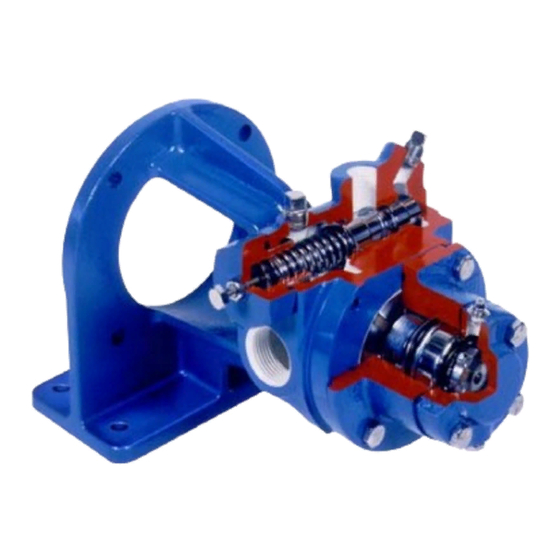
BLACKMER POWER PUMPS
INSTALLATION OPERATION AND MAINTENANCE INSTRUCTIONS
MODELS: LGF1E, LGB1E, LGF1PE, LGB1PE
TABLE OF CONTENTS
Technical Data ...................................................... 2
Initial Pump Start Up Information ........................... 2
Pre-Installation Cleaning ....................................... 3
Location and Piping ............................................... 3
Pump Relief Valve and Bypass valve .................... 3
Check Valves ........................................................ 4
Mounting ............................................................... 4
Motor Adaptors ...................................................... 4
Coupling Alignment ............................................... 4
Pump Rotation....................................................... 4
To Change Pump Rotation .................................... 4
Pre-Start Up Check List ......................................... 5
Start Up Procedures .............................................. 5
Relief Valve Setting and Adjustment ..................... 5
Strainers ................................................................... 6
Lubrication ................................................................ 6
Vane Replacement ................................................... 7
Pump Disassembly .................................................. 7
Parts Replacement ................................................... 8
Pump Assembly ....................................................... 8
TROUBLE SHOOTING ................................................. 11
Numbers in parentheses following individual parts indicate
reference numbers on Blackmer Parts List No. 501-A01.
Blackmer pump manuals and parts lists may be obtained from
Blackmer's website (www.blackmer.com) or by contacting
Blackmer Customer Service.
When you see this symbol on the product, or in the manual,
look for one of the following signal words and be alert to the
potential for personal injury, death or major property
Warns of hazards that WILL cause serious personal injury,
Page
Warns of hazards that CAN cause serious personal injury,
Warns of hazards that CAN cause personal injury
Indicates special instructions which are very
Blackmer liquefied gas pumps MUST only be
installed in systems which have been designed by
qualified engineering personnel. The system MUST
conform
regulations and safety standards.
This manual is intended to assist in the installation
and operation of the Blackmer liquefied gas pumps,
and MUST be kept with the pump.
Blackmer liquefied gas pump service shall be
performed by qualified technicians ONLY. Service
shall conform to all applicable local and national
regulations and safety standards.
Thoroughly review this manual, all Instructions and
hazard warnings, BEFORE performing any work on
the Blackmer liquefied gas pumps.
Maintain ALL system and Blackmer liquefied gas
pump operation and hazard warning decals.
960400
INSTRUCTIONS NO. 501-A00
Section
Effective
Replaces
SAFETY DATA
This is a SAFETY ALERT SYMBOL.
damage
death or major property damage.
death or major property damage.
or property damage.
NOTICE:
important and must be followed.
NOTICE:
to
all
applicable
local
501
Aug 2014
Jan 2014
and
national
Advertisement
Table of Contents

Subscribe to Our Youtube Channel
Related Manuals for BLACKMER LGF1E


Summary of Contents for BLACKMER LGF1E
-
Page 1: Table Of Contents
Blackmer Parts List No. 501-A01. regulations and safety standards. Blackmer pump manuals and parts lists may be obtained from Thoroughly review this manual, all Instructions and Blackmer's website (www.blackmer.com) or by contacting hazard warnings, BEFORE performing any work on Blackmer Customer Service. -
Page 2: Pump Data
A pump Identification tag, containing the pump serial number, I.D. number, and model designation, is attached to each pump. It is recommended that the data from this tag be recorded and filed for future reference. If replacement parts are needed, or if information pertaining to the pump is required, this data must be furnished to a Blackmer representative. TECHNICAL DATA INITIAL PUMP START UP INFORMATION Model No.: ____________________________________... -
Page 3: Installation
Install pressure gauges in the NPT ports provided in the NOTICE: pump casing to check pump performance at start up. Blackmer pumps must only be installed in systems Check alignment of pipes to pump to avoid strains, which designed by qualified engineering personnel. -
Page 4: Check Valves
INSTALLATION CHECK VALVES COUPLING ALIGNMENT The use of check valves or foot valves in the supply tank is The pump must be directly coupled to a gear reducer and/or not recommended with self-priming, positive displacement driver with a flexible coupling. Verify coupling alignment after pumps. -
Page 5: Operation
OPERATION Disconnecting fluid or pressure Operation without guards in place can containment components during pump cause serious personal injury, major operation can cause serious personal property damage, or death. injury or property damage. Hazardous pressure Do not operate can cause serious without guard personal injury or in place... -
Page 6: Maintenance
MAINTENANCE: Failure to disconnect and lockout Failure to disconnect and lockout electrical power or engine drive before electrical power before attempting attempting maintenance can cause maintenance can cause shock, burns or severe personal injury or death death Hazardous Hazardous voltage. machinery can Can shock, burn or cause serious... -
Page 7: Vane Replacement
MAINTENANCE: VANE REPLACEMENT PUMP DISASSEMBLY NOTICE: NOTICE: Follow all hazard warnings and instructions provided in Maintenance shall performed qualified the “Maintenance” section of this manual. technicians only. Following the appropriate procedures NOTE: The numbers in parentheses following individual parts and warnings as presented in manual. indicate reference numbers on the Pump Parts List. -
Page 8: Parts Replacement
MAINTENANCE: PARTS REPLACEMENT 13. Apply a light coating of quality O-ring lubricant to the shaft end to be inserted into the cylinder. 1. If any of the O-rings have been removed or disturbed during disassembly, they must be replaced with new O- 14. - Page 9 MAINTENANCE: 28. Apply a light coating of quality O-ring lubricant on the 40. Loosen both locknuts (24A) one complete turn. shaft to facilitate head installation. 41. Tighten one locknut (24A) until a slight rotor drag is felt 29. With the tell-tale hole towards the bottom of the pump, when turning the shaft by hand.
- Page 10 MAINTENANCE: RELIEF VALVE ASSEMBLY Insert the valve (9) into the relief valve bore of the casing with the small end inward. Install relief valve disc (9A) into relief valve. Install the relief valve spring (8) in the valve bore. Install new O-ring (4A) on spring guide (7). Install spring guide (7) in valve bore of cylinder, aligning spring (8) on spring guide during assembly.
-
Page 11: Trouble Shooting
PUMP TROUBLESHOOTING NOTICE: Maintenance shall be performed by qualified technicians only, following the appropriate procedures and warnings as presented in this manual. SYMPTOM PROBABLE CAUSE 1. Pump not wetted. Pump Not Priming 2. Worn vanes. 3. Internal control valve closed. 4. - Page 12 Accessories Dispensing, Transfer, In-line Gear Reducers, Bypass Valves, Strainers Visit www.blackmer.com for complete information on all Blackmer products 1809 Century Avenue, Grand Rapids, Michigan 49503-1530 U.S.A. Telephone: (616) 241-1611 • Fax: (616) 241-3752 E-mail: blackmer@blackmer.com • Internet Address: www .blackmer.com...
Need help?
Do you have a question about the LGF1E and is the answer not in the manual?
Questions and answers