Table of Contents
Advertisement
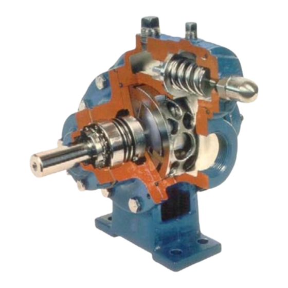
BLACKMER POWER PUMPS
INSTALLATION OPERATION AND MAINTENANCE INSTRUCTIONS
MODELS: LGRL1.25, LGRLF1.25A, LGL1.25,
LGLF1.25A, LGL1.5, LGLF1.5A
Discontinued Models: LGRLF1.25, LGLF1.25
Patent Protected by U.S. Patent 6030191 and Related Foreign Patents.
TABLE OF CONTENTS
Technical Data ...................................................... 2
Initial Pump Start Up Information ........................... 2
Pre-Installation Cleaning ....................................... 3
Location and Piping ............................................... 3
Pump Relief Valve and Bypass valve .................... 3
Check Valves ........................................................ 4
Mounting ............................................................... 4
Motor Adaptors ...................................................... 4
Coupling Alignment ............................................... 4
Pump Rotation....................................................... 4
To Change Pump Rotation .................................... 4
Pre-Start Up Check List ......................................... 5
Start Up Procedures .............................................. 5
Relief Valve Setting and Adjustment ..................... 5
Strainers ................................................................... 6
Lubrication ................................................................ 6
Vane Replacement ................................................... 7
Pump Disassembly .................................................. 7
Parts Replacement ................................................... 7
Pump Assembly ....................................................... 8
TROUBLE SHOOTING ................................................. 10
Numbers in parentheses following individual parts indicate
reference numbers on Blackmer Parts List No. 501-B01.
Blackmer pump manuals and parts lists may be obtained from
Blackmer's website (www.blackmer.com) or by contacting
Blackmer Customer Service.
When you see this symbol on the product, or in the manual,
look for one of the following signal words and be alert to the
potential for personal injury, death or major property
Warns of hazards that WILL cause serious personal injury,
Warns of hazards that CAN cause serious personal injury,
Page
Warns of hazards that CAN cause personal injury
Indicates special instructions which are very
Blackmer liquefied gas pumps MUST only be
installed in systems which have been designed by
qualified engineering personnel. The system MUST
conform
regulations and safety standards.
This manual is intended to assist in the installation
and operation of the Blackmer liquefied gas pumps,
and MUST be kept with the pump.
Blackmer liquefied gas pump service shall be
performed by qualified technicians ONLY. Service
shall conform to all applicable local and national
regulations and safety standards.
Thoroughly review this manual, all Instructions and
hazard warnings, BEFORE performing any work on
the Blackmer liquefied gas pumps.
Maintain ALL system and Blackmer liquefied gas
pump operation and hazard warning decals.
960409
INSTRUCTIONS NO. 501-B00
Section
Effective
Replaces
SAFETY DATA
This is a SAFETY ALERT SYMBOL.
damage
death or major property damage.
death or major property damage.
or property damage.
NOTICE:
important and must be followed.
NOTICE:
to
all
applicable
local
501
Aug 2014
Jan 2014
and
national
Advertisement
Table of Contents

Subscribe to Our Youtube Channel
Related Manuals for BLACKMER LGRL1.25


Summary of Contents for BLACKMER LGRL1.25
-
Page 1: Table Of Contents
BEFORE performing any work on reference numbers on Blackmer Parts List No. 501-B01. the Blackmer liquefied gas pumps. Blackmer pump manuals and parts lists may be obtained from Blackmer's website (www.blackmer.com) or by contacting Maintain ALL system and Blackmer liquefied gas Blackmer Customer Service. -
Page 2: Pump Data
A pump Identification tag, containing the pump serial number, I.D. number, and model designation, is attached to each pump. It is recommended that the data from this tag be recorded and filed for future reference. If replacement parts are needed, or if information pertaining to the pump is required, this data must be furnished to a Blackmer representative. TECHNICAL DATA INITIAL PUMP START UP INFORMATION Model No.: ____________________________________... -
Page 3: Installation
Install pressure gauges in the NPT ports provided in the NOTICE: pump casing to check pump performance at start up. Blackmer pumps must only be installed in systems designed by qualified engineering personnel. System ALL piping and fittings MUST be properly supported to design must conform with all applicable regulations and prevent any piping loads from being placed on the pump. -
Page 4: Check Valves
INSTALLATION CHECK VALVES COUPLING ALIGNMENT The use of check valves or foot valves in the supply tank is The pump must be directly coupled to a gear reducer and/or not recommended with self-priming, positive displacement driver with a flexible coupling. Verify coupling alignment after pumps. -
Page 5: Operation
PRE-START UP CHECK LIST cap. Check the alignment of the pipes to the pump. Pipes Refer to the individual Blackmer pump parts lists for various should be supported so that they do not spring away or spring pressure ranges. drop down when pump flanges or union joints are disconnected. -
Page 6: Maintenance
MAINTENANCE Failure to disconnect and lockout Failure to disconnect and lockout electrical power before attempting electrical power before attempting maintenance can cause shock, burns maintenance can cause shock, burns or or death death Hazardous Hazardous voltage. machinery can Can shock, burn or cause serious cause death. -
Page 7: Vane Replacement
MAINTENANCE VANE REPLACEMENT 3. Remove the inboard bearing cover capscrews (28) and slide the inboard bearing cover (27) and gasket (26) off the NOTICE: shaft. Discard the bearing cover gasket. Maintenance shall performed qualified NOTE: On flange mounted pumps, a motor adaptor (108) technicians only. -
Page 8: Pump Assembly
MAINTENANCE PUMP ASSEMBLY b. If the pump is equipped with the four-vane rotor and Before reassembling the pump, inspect all component shaft (13A), hold the two bottom vanes (14) in place while inserting the two push rods (77). parts for wear or damage, and replace as required. Wash out the bearing/seal recess of the head and c. - Page 9 MAINTENANCE 17. Attach a new bearing cover gasket (26) and the inboard bearing cover (27) to the inboard head (20). Install the outboard bearing cover (27A) and a new gasket to the outboard head. Make sure the grease fittings (76) on the bearing covers are accessible.
-
Page 10: Troubleshooting
TROUBLESHOOTING NOTICE: Maintenance shall be performed by qualified technicians only, following the appropriate procedures and warnings as presented in this manual. SYMPTOM PROBABLE CAUSE 1. Pump not wetted. Pump Not Priming 2. Worn vanes. 3. Internal control valve closed. 4. Strainer clogged. 5. - Page 11 NOTES 501-B00 Page 11/12...
- Page 12 Accessories Dispensing, Transfer, In-line Gear Reducers, Bypass Valves, Strainers Visit www.blackmer.com for complete information on all Blackmer products 1809 Century Avenue, Grand Rapids, Michigan 49503-1530 U.S.A. Telephone: (616) 241-1611 • Fax: (616) 241-3752 E-mail: blackmer@blackmer.com • Internet Address: www .blackmer.com...
Need help?
Do you have a question about the LGRL1.25 and is the answer not in the manual?
Questions and answers