IEI Technology WSB-H610 Quick Installation Manual
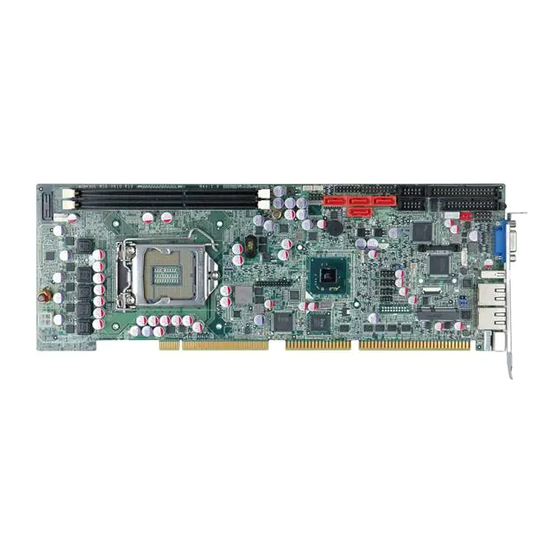
Full-size picmg 1.0 cpu card supports 32nm lga1155 intel core i7/i5/i3 cpu per intel h61, ddr3, vga/dvi-d, dual realtek pcie gbe, usb 2.0, sata 3gb/s, com, hd audio and rohs
Hide thumbs
Also See for WSB-H610:
- User manual (187 pages) ,
- Quick installation manual (13 pages) ,
- User manual (146 pages)
Table of Contents
Advertisement
Quick Links
Full-size PICMG 1.0 CPU card supports 32nm LGA1155
Intel® Core™ i7/i5/i3 CPU per Intel® H61, DDR3,
VGA/DVI-D, Dual Realtek PCIe GbE, USB 2.0, SATA 3Gb/s,
Quick Installation Guide
Package Contents
WSB-H610 package includes the following items:
1 x WSB-H610 Single Board Computer
1 x Dual RS-232 Cable (P/N:19800-000051-RS)
1 x KB/MS Y cable( P/N: 32000-133200-RS)
2 x SATA Cable (P/N:32000-0628000-RS)
1 x USB Cable (P/N: CB-USB02-RS)
1 x DVI and USB Kit (P/N:IO-KIT-001-R20)( DVI SKU only)
1 x Mini Jumper Pack
1 x Utility CD
1 x QIG (Quick Installation Guide)
©2006 Copyright by IEI Integration corp.
All manuals and user guides at all-guides.com
COM, HD Audio and RoHS
WSB-H610
Version 1.10
May 22, 2015.
All rights reserved.
1
Advertisement
Table of Contents

Related Manuals for IEI Technology WSB-H610


Summary of Contents for IEI Technology WSB-H610
- Page 1 COM, HD Audio and RoHS WSB-H610 Quick Installation Guide Version 1.10 May 22, 2015. Package Contents WSB-H610 package includes the following items: 1 x WSB-H610 Single Board Computer 1 x Dual RS-232 Cable (P/N:19800-000051-RS) 1 x KB/MS Y cable( P/N: 32000-133200-RS) ...
-
Page 2: Specifications
All manuals and user guides at all-guides.com Specifications CPU LGA1155 socket supports Intel® Core™ i7/i5/i3/Pentium® /Celeron® processor System Chipset: Intel® H61 BIOS: UEFI BIOS System Memory: Two 240-pin 1333/1066MHz dual-channel DDR3 & DDR3L(1.35V) DIMMs supported.(system max. 16GB) ... -
Page 3: Ordering Information
Dimensions: 338mm X 126mm Weight: 1.2Kg Ordering Information WSB-H610-R11: Full-size PICMG 1.0 CPU card supports 32nm LGA1155 Intel® Core™ i7/i5/i3 CPU per Intel® H61, DDR3, VGA, Dual Realtek PCIe GbE, USB 2.0, SATA 3Gb/s, COM, HD Audio and RoHS WSB-H610-DVI-R10 : Full-size PICMG 1.0 CPU card supports 32nm... - Page 4 All manuals and user guides at all-guides.com AC-KIT-888HD-R10: 7.1 channel HD Audio kit with Realtek ALC888 support dual audio streams AC-KIT08R-R10: 5.1 channel AC’97 audio kit with Realtek ALC655 CPU-DT-i5-2500T: Intel® Core™ i5-2500T processor, LGA1155, Quad core 2.3GHz, 6M Cache, 45W, compatible with CF-1156C-RS CPU cooler CPU-DT-i5-2390T: Intel®...
-
Page 5: Jumpers Setting And Connectors
All manuals and user guides at all-guides.com Jumpers setting and Connectors Table of Jumpers LABEL FUNCTION J_CMOS1 CMOS state setting JAUTO1 Power Mode Setting JLAN_PWR1 WOL Setting J_FLASH Flash Descriptor Security Override/ME Debug Mode Table of Connectors LABEL FUNCTION VGA1 VGA 15-pin Female Connector USB_C1 USB Port Connector... -
Page 6: Jumper Setting
All manuals and user guides at all-guides.com Jumper setting J_CMOS1 : Clear CMOS setting Jumper J_CMOS1 DESCRIPTION Normal (Default) Clear CMOS Data J_ATXCTL1 : Set The Power mode JATX_AT1 DESCRIPTION ATX Power Mode (Default) (ON) AT Power Mode (OFF) JLAN_PWR1 : WOL enable jumper PIN NO. - Page 7 All manuals and user guides at all-guides.com DDCDAT HSYNC VSYNC DDCCLK USB_C1,USB_C2 PIN NO. DESCRIPTION DATA- DATA+ GROUND LAN1、LAN2: RJ45 LAN Connector PIN NO. DESCRIPTION PIN NO. DESCRIPTION MDIA3- MDIA1+ MDIA3+ MDIA2+- MDIA2- MDIA0- MDIA1- MDIA0+ MS/KB1: Internal 6-pin Keyboard Connector DESCRIPTION Mouse Data Mouse Clock...
-
Page 8: Pin Description
All manuals and user guides at all-guides.com RXD485+ RXD485# ● ● ● ■ RS422/485 RS422 Pin define RS485 Pin define TX-(TXD485#) TX-(TXD485#) TX+(TXD485+) TX+(TXD485+) RX+(RXD485+) RX-(RXD485#) D-SUB 9PIN MALE D-SUB 9PIN MALE USB1-USB3: Internal USB Connector PIN DESCRIPTION DESCRIPTION DATA- DATA+ DATA+ DATA-... - Page 9 All manuals and user guides at all-guides.com IR1: IrDA connector PIN NO. DESCRIPTION IR-RX IR-TX FDD1: Floppy Disk Drive Connector DESCRIPTION DESCRIPTION REDUCE WRITE INDEX# MOTOR ENABLE A# DRIVE SELECT B# DRIVE SELECT A# MOTOR ENABLE B# DIRECTION# STEP# WRITE DATA# WRITE GATE# TRACK 0# WRITE PROTECT#...
- Page 10 All manuals and user guides at all-guides.com LPT1 : Parallel Port Connector DESCRIPTION DESCRIPTION STROBE# AUTO FORM FEED # DATA0 ERROR# DATA1 INITIALIZE# DATA2 PRINTER SELECT LN# DATA3 DATA4 DATA5 DATA6 DATA7 ACKNOWLEDGE# BUSY PAPER EMPTY PRINTER SELECT DVI1 : DVI Connector PIN NO.
- Page 11 All manuals and user guides at all-guides.com DIO1 : Digital Input / Output Connector PIN NO. DESCRIPTION PIN NO. DESCRIPTION Ground Output 3 Output 2 Output 1 Output 0 Input 3 Input 2 Input 1 Input 0 F_PANEL1 : External Switches and Indicators panel PIN DESCRIPTION PIN DESCRIPTION Power LED Speaker...
- Page 12 All manuals and user guides at all-guides.com PETN2 SMBDATA PETP2 USBD- USBD+ RF_LINK# BLUELED# 1.5V VCC3 TPM1: TPM Connector PIN NO. DESCRIPTION PIN NO. DESCRIPTION FRAME# RERST# SMB_CLK SMB_DATA SB3V SERIRQ CLKRUN# PM_SUS_STAT# DRQ#...
- Page 13 All manuals and user guides at all-guides.com Board Layout: Jumper and Connector Locations (Unit: mm)
Need help?
Do you have a question about the WSB-H610 and is the answer not in the manual?
Questions and answers