Table of Contents
Advertisement
Quick Links
Advertisement
Table of Contents

Related Manuals for IEI Technology WAFER-BT-E38 1W2 Series


Summary of Contents for IEI Technology WAFER-BT-E38 1W2 Series
- Page 1 WAFER-BT-E38xx1W2 WAFER-BT-E38xx1W2 CPU Card MODEL: WAFER-BT-E38xx1W2 ® ® 3.5" SBC with 22nm Intel Atom On-board SoC, VGA, LVDS, iDP, Dual PCIe GbE, USB 3.2 Gen 1, PCIe Mini, SATA 3Gb/s, mSATA, COM, Audio, -40°C – 85°C Operating Temp. and RoHS User Manual Page I Rev.
- Page 2 WAFER-BT-E38xx1W2 Revision Date Version Changes July 12, 2021 1.20 Updated Section 2.3: Packing List Updated Chapter 6: Software Drivers Changed audio IC to ALC888S Removed SIM slot June 30, 2017 1.02 Updated BIOS spec on page 8 January 28, 2016 1.01 Modified Section 6.2 November 10, 2015...
- Page 3 WAFER-BT-E38xx1W2 Copyright COPYRIGHT NOTICE The information in this document is subject to change without prior notice in order to improve reliability, design and function and does not represent a commitment on the part of the manufacturer. In no event will the manufacturer be liable for direct, indirect, special, incidental, or consequential damages arising out of the use or inability to use the product or documentation, even if advised of the possibility of such damages.
- Page 4 WAFER-BT-E38xx1W2 Manual Conventions WARNING Warnings appear where overlooked details may cause damage to the equipment or result in personal injury. Warnings should be taken seriously. CAUTION Cautionary messages should be heeded to help reduce the chance of losing data or damaging the product. NOTE These messages inform the reader of essential but non-critical information.
-
Page 5: Table Of Contents
WAFER-BT-E38xx1W2 Table of Contents 1 INTRODUCTION ......................1 1.1 I ......................2 NTRODUCTION 1.2 M ....................3 ODEL ARIATIONS 1.3 F ........................3 EATURES 1.4 C ......................4 ONNECTORS 1.5 D ....................... 6 IMENSIONS 1.6 D ........................ 7 1.7 T .................. - Page 6 WAFER-BT-E38xx1W2 3.2.11 LVDS LCD Connector ..................30 3.2.12 LAN LED Connectors ..................31 3.2.13 microSD Slot ....................32 3.2.14 mSATA Module Slot ..................32 3.2.15 PCIe Mini Card Slot ..................34 3.2.16 PCIe Mini Card Slot for 3G Module .............. 35 3.2.17 Power Button Connector ................
- Page 7 WAFER-BT-E38xx1W2 4.7.2 Motherboard Installation ................. 63 4.8 I ............63 NTERNAL ERIPHERAL EVICE ONNECTIONS 4.8.1 AT Power Connection ..................63 4.8.2 SATA Drive Connection ................... 65 5 BIOS ..........................67 5.1 I ......................68 NTRODUCTION 5.1.1 Starting Setup ....................68 5.1.2 Using Setup ......................
- Page 8 WAFER-BT-E38xx1W2 5.6 B ........................96 5.7 E ......................... 98 6 SOFTWARE DRIVERS .................... 100 6.1 A ....................101 VAILABLE RIVERS 6.2 D ....................101 RIVER OWNLOAD A REGULATORY COMPLIANCE ................103 B PRODUCT DISPOSAL .................... 105 C BIOS MENU OPTIONS ................... 107 D DIGITAL I/O INTERFACE ..................
- Page 9 WAFER-BT-E38xx1W2 List of Figures Figure 1-1: WAFER-BT-E38xx1W2 ....................2 Figure 1-2: Connectors (Front) ...................... 4 Figure 1-3: Connectors (Rear) ....................... 5 Figure 1-4: Dimensions (mm) ......................6 Figure 1-5: Data Flow Diagram ...................... 7 Figure 3-1: Connector and Jumper Locations (Front) .............. 17 Figure 3-2: Connector and Jumper Locations (Rear) ...............
- Page 10 WAFER-BT-E38xx1W2 Figure 3-27: SPI Flash Connector Location ................45 Figure 3-28: USB Connectors Locations..................46 Figure 3-29: External Peripheral Interface Connector .............. 47 Figure 3-30: LAN Connector ......................47 Figure 3-31: RS-232 Serial Port Connector ................49 Figure 3-32: VGA Connector ....................... 50 Figure 4-1: Removing the Retention Screw ................
- Page 11 WAFER-BT-E38xx1W2 List of Tables Table 1-1: WAFER-BT-E38xx1W2 Model Variations ..............3 Table 1-2: Technical Specifications .................... 10 Table 3-1: Peripheral Interface Connectors ................19 Table 3-2: Rear Panel Connectors ....................20 Table 3-3: +12V DC-IN Power Connector Pinouts ..............21 Table 3-4: Audio Connector Pinouts ..................
- Page 12 WAFER-BT-E38xx1W2 Table 3-30: USB 3.2 Gen 1 Port Pinouts ..................48 Table 3-31: RS-232 Serial Port Connector Pinouts ..............49 Table 3-32: VGA Connector Pinouts ................... 50 Table 4-1: AT/ATX Mode Select Switch Settings ............... 59 Table 4-2: Clear CMOS Button Settings ..................59 Table 4-3: LVDS Panel Resolution Selection ................
- Page 13 WAFER-BT-E38xx1W2 List of BIOS Menus BIOS Menu 1: Main ........................70 BIOS Menu 2: Advanced ......................71 BIOS Menu 3: ACPI Configuration ....................72 BIOS Menu 4: Super IO Configuration ..................73 BIOS Menu 5: Serial Port n Configuration Menu ............... 73 BIOS Menu 6: Hardware Monitor ....................
-
Page 15: Introduction
WAFER-BT-E38xx1W2 Chapter Introduction Page 1... -
Page 16: Introduction
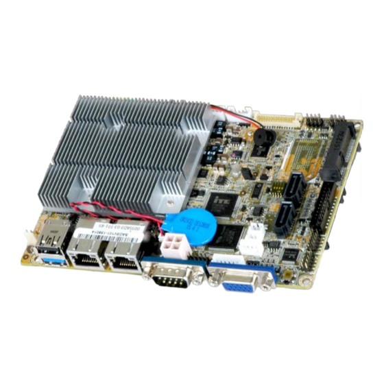
WAFER-BT-E38xx1W2 1.1 Introduction Figure 1-1: WAFER-BT-E38xx1W2 ® ® The WAFER-BT-E38xx1W2 motherboard is an Intel Atom processor platform which supports wide-range operating temperature (-40°C – 85°C). It has 2 GB or 4 GB 1066/1333 MHz DDR3L soldered-down memory. The WAFER-BT-E38xx1W2 includes a VGA connector, a LVDS connector and an iDP connector. -
Page 17: Model Variations
WAFER-BT-E38xx1W2 1.2 Model Variations The model variations of the WAFER-BT-E38xx1W2 series are listed below. Model No. On-board Memory ® ® WAFER-BT-E38451W2 Intel Atom E3845 on-board SoC 4 GB (1.91 GHz, quad-core, 2 MB cache, TDP=10 W) ® ® Intel Atom E3827 on-board SoC 2 GB WAFER-BT-E38271W2*... -
Page 18: Connectors
WAFER-BT-E38xx1W2 1.4 Connectors The connectors on the WAFER-BT-E38xx1W2 are shown in the figure below. Figure 1-2: Connectors (Front) Page 4... -
Page 19: Figure 1-3: Connectors (Rear)
WAFER-BT-E38xx1W2 Figure 1-3: Connectors (Rear) Page 5... -
Page 20: Dimensions
WAFER-BT-E38xx1W2 1.5 Dimensions The dimensions of the board are listed below: Figure 1-4: Dimensions (mm) Page 6... -
Page 21: Data Flow
WAFER-BT-E38xx1W2 1.6 Data Flow Figure 1-5 shows the data flow between the system chipset, the CPU and other components installed on the motherboard. Figure 1-5: Data Flow Diagram Page 7... -
Page 22: Technical Specifications
WAFER-BT-E38xx1W2 1.7 Technical Specifications WAFER-BT-E38xx1W2 technical specifications are listed below. Specification WAFER-BT-E38xx1W2 ® ® Intel Atom E3845 on-board SoC (1.91 GHz, quad-core, 2 MB cache, TDP=10 W) ® ® Intel Atom E3827 on-board SoC (1.75 GHz, dual-core, 1 MB cache, TDP=8 W) ®... - Page 23 WAFER-BT-E38xx1W2 Specification WAFER-BT-E38xx1W2 Realtek ALC888S HD codec Audio Watchdog Timer Software programmable support 1–255 sec. system reset I/O Interface Audio Connector 1 x Analog audio by 10-pin (2x5) header Ethernet Two RJ-45 ports KB/MS 1 x KB/MS by 6-pin (1x6) header Serial Ports 1 x RS-422/485 (by pin header) 2 x RS-232 (1 on rear I/O, 1 by pin header)
-
Page 24: Table 1-2: Technical Specifications
WAFER-BT-E38xx1W2 Specification WAFER-BT-E38xx1W2 -40°C – 85°C Storage Temperature 5% – 95%, non-condensing Humidity Physical Specifications Dimensions 146 mm x 102 mm Weight GW/NW 1000 g / 250 g Table 1-2: Technical Specifications Page 10... -
Page 25: Unpacking
WAFER-BT-E38xx1W2 Chapter Unpacking Page 11... -
Page 26: Anti-Static Precautions
WAFER-BT-E38xx1W2 2.1 Anti-static Precautions WARNING! Static electricity can destroy certain electronics. Make sure to follow the ESD precautions to prevent damage to the product, and injury to the user. Make sure to adhere to the following guidelines: Wear an anti-static wristband: Wearing an anti-static wristband can prevent electrostatic discharge. -
Page 27: Packing List
WAFER-BT-E38xx1W2 2.3 Packing List NOTE: If any of the components listed in the checklist below are missing, do not proceed with the installation. Contact the IEI reseller or vendor the WAFER-BT-E38xx1W2 was purchased from or contact an IEI sales representative directly by sending an email to sales@ieiworld.com. The WAFER-BT-E38xx1W2 is shipped with the following components: Quantity Item and Part Number... -
Page 28: Optional Items
WAFER-BT-E38xx1W2 2.4 Optional Items The following are optional components which may be separately purchased: Item and Part Number Image Dual-port USB cable without bracket (P/N: 32001-008600-200-RS) RS-422/485 cable (P/N: 32205-003800-300-RS) PS/2 KB/MS Y-cable without bracket (P/N: 32006-001100-201-RS) Dual RS-232 cable with bracket (P/N:19800-000300-100-RS) Audio cable (P/N: 32007-005200-200-RS) - Page 29 WAFER-BT-E38xx1W2 DisplayPort to DVI-D converter board for iEi IDP connector (P/N: DP-DVI-R10) DisplayPort to DisplayPort converter board for iEi IDP connector (P/N: DP-DP-R10) Page 15...
-
Page 30: Connectors
WAFER-BT-E38xx1W2 Chapter Connectors Page 16... -
Page 31: Peripheral Interface Connectors
WAFER-BT-E38xx1W2 3.1 Peripheral Interface Connectors This chapter details all the jumpers and connectors. 3.1.1 WAFER-BT-E38xx1W2 Layout The figures below show all the connectors and jumpers. Figure 3-1: Connector and Jumper Locations (Front) Page 17... -
Page 32: Peripheral Interface Connectors
WAFER-BT-E38xx1W2 Figure 3-2: Connector and Jumper Locations (Rear) 3.1.2 Peripheral Interface Connectors The table below lists all the connectors on the board. Connector Type Label +12V DC-IN power connector 4-pin Molex POWER1 Audio connector 10-pin header AUDIO1 Battery connector 2-pin wafer BAT1 Buzzer connector 2-pin wafer... -
Page 33: Table 3-1: Peripheral Interface Connectors
WAFER-BT-E38xx1W2 LCD backlight inverter connector 5-pin wafer INV1 LVDS LCD connector 30-pin crimp LVDS1 LAN LED connectors 2-pin header JP2, JP3 microSD slot microSD slot MICROSD1 mSATA module slot Half-size PCIe Mini slot MSATA1 PCIe Mini card slot Full-size PCIe Mini slot MPCIE1 PCIe Mini card slot for 3G module Full-size PCIe Mini slot... -
Page 34: External Interface Panel Connectors
WAFER-BT-E38xx1W2 3.1.3 External Interface Panel Connectors The table below lists the connectors on the external I/O panel. Connector Type Label LAN connectors RJ-45 LAN1, LAN2 RS-232 serial port connector DB-9 male COM1 USB 2.0 and USB 3.2 Gen 1 connector USB Type-A CON1 VGA Connector... -
Page 35: Audio Connector
WAFER-BT-E38xx1W2 PIN NO. DESCRIPTION PIN NO. DESCRIPTION +12V +12V Table 3-3: +12V DC-IN Power Connector Pinouts 3.2.2 Audio Connector CN Label: AUDIO1 CN Type: 10-pin header, p=2.00 mm CN Location: See Figure 3-4 CN Pinouts: See Table 3-4 The audio connector is connected to external audio devices including speakers and microphones for the input and output of audio signals to and from the system. -
Page 36: Battery Connector
WAFER-BT-E38xx1W2 3.2.3 Battery Connector CAUTION: Risk of explosion if battery is replaced by an incorrect type. Only certified engineers should replace the on-board battery. Dispose of used batteries according to instructions and local regulations. CN Label: BAT1 CN Type: 2-pin wafer, p=1.25 mm CN Location: See Figure 3-5 CN Pinouts:... -
Page 37: Buzzer Connector
WAFER-BT-E38xx1W2 3.2.4 Buzzer Connector CN Label: CN Type: 2-pin wafer, p=1.25 mm CN Location: See Figure 3-6 CN Pinouts: See Table 3-6 The buzzer connector is connected to the buzzer. NOTE: If you cannot find a good place to put a buzzer on the WAFER-BT-E38xx1W2, it is recommended to attach the buzzer onto the system chassis in which the WAFER-BT-E38xx1W2 is installed. -
Page 38: Cpu Fan Connector
WAFER-BT-E38xx1W2 3.2.5 CPU Fan Connector CN Label: CPU_FAN1 4-pin wafer, p=2.54 mm CN Type: CN Location: See Figure 3-7 CN Pinouts: See Table 3-7 The fan connector attaches to a cooling fan. Figure 3-7: CPU Fan Connector Locations Description +12V FANIO1 FANOUT1 Table 3-7: CPU Fan Connector Pinouts... -
Page 39: Digital I/O Connector
WAFER-BT-E38xx1W2 3.2.6 Digital I/O Connector CN Label: DIO1 10-pin header, p=2.00 mm CN Type: CN Location: See Figure 3-8 CN Pinouts: See Table 3-8 The digital I/O connector provides programmable input and output for external devices. The digital I/O provides 4-bit output and 4-bit input. Figure 3-8: Digital I/O Connector Location PIN NO. -
Page 40: Display Port Connector
WAFER-BT-E38xx1W2 3.2.7 Display Port Connector CN Label: 20-pin box header, p=2.00 mm CN Type: CN Location: See Figure 3-9 CN Pinouts: See Table 3-9 The disport port connector provides flexible display function that supports VGA, DVI, LVDS, HDMI and DisplayPort via the display port convert board. Figure 3-9: Display Port Connector Location Description Description... -
Page 41: Front Panel Connector
WAFER-BT-E38xx1W2 3.2.8 Front Panel Connector CN Label: 6-pin wafer, p=2.00 mm CN Type: CN Location: See Figure 3-10 CN Pinouts: See Table 3-10 The front panel connector connects to the indicator LEDs on the system front panel. Figure 3-10: Front Panel Connector Location Description PWR_LED+ PWR_LED-... -
Page 42: Keyboard And Mouse Connector
WAFER-BT-E38xx1W2 3.2.9 Keyboard and Mouse Connector CN Label: KB_MS1 6-pin wafer, p=2.00 mm CN Type: CN Location: See Figure 3-11 CN Pinouts: See Table 3-11 The keyboard/mouse connector connects to a PS/2 Y-cable that can be connected to a PS/2 keyboard and mouse. Figure 3-11: Keyboard and Mouse Location Description Mouse Data... -
Page 43: Lvds Backlight Inverter Connector
WAFER-BT-E38xx1W2 3.2.10 LVDS Backlight Inverter Connector CN Label: INV1 5-pin wafer, p=2.00 mm CN Type: CN Location: See Figure 3-12 CN Pinouts: See Table 3-12 The backlight inverter connector provides power to an LCD panel. Figure 3-12: Backlight Inverter Connector Location Description BRIGHTNESS ENABKL... -
Page 44: Lvds Lcd Connector
WAFER-BT-E38xx1W2 3.2.11 LVDS LCD Connector CN Label: LVDS1 30-pin crimp, p=1.25 mm CN Type: CN Location: See Figure 3-13 CN Pinouts: See Table 3-13 The LVDS connector is for an LCD panel connected to the board. Figure 3-13: LVDS Connector Location Description Description GROUND... -
Page 45: Lan Led Connectors
WAFER-BT-E38xx1W2 Description Description GROUND GROUND +LCD VCC +LCD VCC +LCD VCC +LCD VCC Table 3-13: LVDS Connector Pinouts 3.2.12 LAN LED Connectors CN Label: JP1, JP2 CN Type: 2-pin header, p=2.00 mm CN Location: See Figure 3-14 CN Pinouts: See Table 3-14 The LAN LED connectors connect to the LAN link LEDs on the system. -
Page 46: Microsd Slot
WAFER-BT-E38xx1W2 3.2.13 microSD Slot CN Label: MICROSD1 microSD card slot CN Type: CN Location: See Figure 3-15 The microSD card slot accepts a microSD card for storage. Figure 3-15: microSD Card Slot Location 3.2.14 mSATA Module Slot CAUTION: If an mSATA module is installed in the mSATA slot (MSATA1), the SATA port 2 (SATA2) will be disabled. -
Page 47: Figure 3-16: Msata Module Slot Location
WAFER-BT-E38xx1W2 The PCIe Mini card slot is for installing an mSATA module. Figure 3-16: mSATA Module Slot Location Description Description VCC3 SATARXP1 VCC3 SATARXN1 SMBCLK SATATXN1_C SMBDATA SATATXP1_C VCC3 VCC3 Page 33... -
Page 48: Pcie Mini Card Slot
WAFER-BT-E38xx1W2 Description Description M-SATADET VCC3 Table 3-15: mSATA Module Slot Pinouts 3.2.15 PCIe Mini Card Slot CN Label: MPCIE1 Full-size PCIe Mini card slot CN Type: CN Location: See Figure 3-17 CN Pinouts: See Table 3-16 The PCIe Mini card slot is for installing a PCIe Mini expansion card. Figure 3-17: PCIe Mini Card Slot Location Description Description... -
Page 49: Pcie Mini Card Slot For 3G Module
WAFER-BT-E38xx1W2 Description Description BUF_PLT_RST# VCC3 BUF_PLT_RST# PCIE_RX4DN_M VCC3 PCIE_RX4DP_M 1.5 V SMBCLK PCIE_TX4DN_CM SMBDATA PCIE_TX4DP_CM VCC3 VCC3 RF_LINK# BLUELED# 1.5 V VCC3 Table 3-16: PCIe Mini Card Slot Pinouts 3.2.16 PCIe Mini Card Slot for 3G Module CN Label: MINI_PCIE1 CN Type: Full-size PCIe Mini card slot CN Location:... -
Page 50: Figure 3-18: Pcie Mini 3G Module Slot Location
WAFER-BT-E38xx1W2 Figure 3-18: PCIe Mini 3G Module Slot Location Description Description PCIE_WAKE# VCC3 1.5 V SIM1_VCC SIM1_CIO CLK- SIM1_CLK CLK+ SIM1_RST BUF_PLT_RST# VCC3 BUF_PLT_RST# PCIE_MINI2_RXN VCC3 PCIE_MINI2_RXP 1.5 V SMBCLK PCIE_MINI2_TXN SMBDATA PCIE_MINI2_TXP USB_PN3- USB_PP3+ VCC3 VCC3 Page 36... -
Page 51: Power Button Connector
WAFER-BT-E38xx1W2 Description Description 1.5 V VCC3 Table 3-17: PCIe Mini 3G Module Slot Pinouts 3.2.17 Power Button Connector CN Label: PWR_BTN1 2-pin wafer, p=2.00 mm CN Type: CN Location: See Figure 3-19 CN Pinouts: See Table 3-18 The power button connector is connected to a power switch on the system chassis to enable users to turn the system on and off. -
Page 52: Reset Button Connector
WAFER-BT-E38xx1W2 3.2.18 Reset Button Connector CN Label: RST_BTN1 2-pin wafer, p=2.00 mm CN Type: CN Location: See Figure 3-20 CN Pinouts: See Table 3-19 The reset button connector is connected to a reset switch on the system chassis to enable users to reboot the system when the system is turned on. -
Page 53: Serial Port Connector
WAFER-BT-E38xx1W2 3.2.19 RS-232 Serial Port Connector CN Label: COM2 10-pin header, p=2.00 mm CN Type: CN Location: See Figure 3-21 CN Pinouts: See Table 3-20 The serial connector provides RS-232 connection. Figure 3-21: RS-232 Serial Port Connectors Location PIN NO. DESCRIPTION PIN NO. -
Page 54: Rs-422/485 Serial Port Connector
WAFER-BT-E38xx1W2 3.2.20 RS-422/485 Serial Port Connector CN Label: COM3 4-pin wafer, p=2.00 mm CN Type: CN Location: See Figure 3-22 CN Pinouts: See Table 3-21 This connector provides RS-422 or RS-485 communications. Figure 3-22: RS-422/485 Connector Location Description RXD422- RXD422+ TXD422+/TXD485+ TXD422-/TXD485- Table 3-21: RS-422/485 Connector Pinouts... -
Page 55: Sata 3Gb/S Drive Connectors
WAFER-BT-E38xx1W2 RS-422 Pinouts RS-485 Pinouts Table 3-22: DB-9 RS-422/485 Pinouts 3.2.21 SATA 3Gb/s Drive Connectors CN Label: SATA1, SATA2 CN Type: 7-pin SATA connector CN Location: See Figure 3-23 The SATA 3Gb/s drive connector is connected to a SATA 3Gb/s drive. The SATA 3Gb/s drive transfers data at speeds as high as 3Gb/s. -
Page 56: Sata Power Connectors
WAFER-BT-E38xx1W2 3.2.22 SATA Power Connectors CN Label: SATA_PWR1, SATA_PWR2 CN Type: 2-pin wafer, p=2.00 mm CN Location: See Figure 3-24 CN Pinouts: See Table 3-23 The SATA power connector provides +5V power output to the SATA connector. Figure 3-24: SATA Power Connector Locations Description Table 3-23: SATA Power Connector Pinouts Page 42... -
Page 57: Smbus Connectors
WAFER-BT-E38xx1W2 3.2.23 SMBus Connectors CN Label: CN2, CN9 4-pin wafer, p=1.25 mm CN Type: CN Location: See Figure 3-25 CN Pinouts: See Table 3-24 The SMBUS (System Management Bus) connector provides low-speed system management communications. Figure 3-25: SMBUS Connectors Location Description SMBDATA SMBCLK... -
Page 58: Spi Flash Connector, Bios
WAFER-BT-E38xx1W2 3.2.24 SPI Flash Connector, BIOS CN Label: JSPI1 6-pin wafer, p=1.25 mm CN Type: CN Location: See Figure 3-26 CN Pinouts: See Table 3-25 The 6-pin SPI Flash connector is used to flash the BIOS. Figure 3-26: SPI Flash Connector Location Description +1.8VA SPI_CS... -
Page 59: Spi Flash Connector, Ec
WAFER-BT-E38xx1W2 3.2.25 SPI Flash Connector, EC CN Label: JSPI2 6-pin wafer, p=1.25 mm CN Type: CN Location: See Figure 3-27 CN Pinouts: See Table 3-26 The 6-pin SPI Flash connector is used to flash the embedded controller. Figure 3-27: SPI Flash Connector Location Description +3.3VA SPI_CS#0_CN_EC... -
Page 60: Usb Connectors
WAFER-BT-E38xx1W2 3.2.26 USB Connectors CN Label: USB1_2, USB3_4 CN Type: 8-pin header, p=2.00 mm CN Location: See Figure 3-28 CN Pinouts: See Table 3-27 The USB connectors provide four USB 2.0 ports by dual-port USB cable. Figure 3-28: USB Connectors Locations PIN NO. -
Page 61: External Peripheral Interface Connector Panel
WAFER-BT-E38xx1W2 3.3 External Peripheral Interface Connector Panel Figure 3-29 shows the WAFER-BT-E38xx1W2 external peripheral interface connector (EPIC) panel. The EPIC panel consists of the following: 2 x LAN connectors 1 x USB 3.2 Gen 1 (5Gb/s) connector 1 x USB 2.0 connector ... -
Page 62: Usb Connectors
WAFER-BT-E38xx1W2 Description Description TRD0+ TRD2+ TRD0- TRD2- TRD1+ TRD3+ TRD1- TRD3- Table 3-28: LAN Pinouts 3.3.2 USB Connectors CN Label: CON1 CN Type: USB Type-A ports CN Location: See Figure 3-29 CN Pinouts: See Table 3-29 and Table 3-30 The WAFER-BT-E38xx1W2 has one external USB 2.0 port and one external USB 3.2 Gen 1 (5Gb/s) port. -
Page 63: Serial Port Connector
WAFER-BT-E38xx1W2 3.3.3 RS-232 Serial Port Connector CN Label: COM1 CN Type: DB-9 Male CN Location: See Figure 3-29 CN Pinouts: See Figure 3-31 and Table 3-31 The serial port connects to a RS-232 serial communications device. Figure 3-31: RS-232 Serial Port Connector Description Description DCD1... -
Page 64: Vga Connector
WAFER-BT-E38xx1W2 3.3.4 VGA Connector CN Label: VGA1 15-pin female (VGA) CN Type: CN Location: See Figure 3-29 CN Pinouts: See Figure 3-32 and Table 3-32 The VGA port connects to a monitor that accepts a standard VGA input. Figure 3-32: VGA Connector Description Description Green... -
Page 65: Installation
WAFER-BT-E38xx1W2 Chapter Installation Page 51... -
Page 66: Anti-Static Precautions
WAFER-BT-E38xx1W2 4.1 Anti-static Precautions WARNING: Failure to take ESD precautions during the installation of the WAFER-BT-E38xx1W2 may result in permanent damage to the WAFER-BT-E38xx1W2 and severe injury to the user. Electrostatic discharge (ESD) can cause serious damage to electronic components, including the WAFER-BT-E38xx1W2. - Page 67 WAFER-BT-E38xx1W2 WARNING: The installation instructions described in this manual should be carefully followed in order to prevent damage to the WAFER-BT-E38xx1W2, WAFER-BT-E38xx1W2 components and injury to the user. Before and during the installation please DO the following: Read the user manual: The user manual provides a complete description of the WAFER-BT-E38xx1W2 installation instructions and configuration options.
-
Page 68: Full-Size Pcie Mini Card Installation
WAFER-BT-E38xx1W2 4.3 Full-size PCIe Mini Card Installation The PCIe Mini card slot allows installation of either a full-size PCIe Mini card. To install a full-size PCIe Mini card, please follow the steps below. Step 1: Locate the PCIe Mini card slot. See Figure 3-16. Step 2: Remove the retention screw. -
Page 69: Figure 4-2: Inserting The Full-Size Pcie Mini Card Into The Slot At An Angle
WAFER-BT-E38xx1W2 Figure 4-2: Inserting the Full-size PCIe Mini Card into the Slot at an Angle Step 4: Secure the full-size PCIe Mini card. Secure the full-size PCIe Mini card with the retention screw previously removed (Figure 4-3). Figure 4-3: Securing the Full-size PCIe Mini Card Page 55... -
Page 70: Microsd Card Installation
WAFER-BT-E38xx1W2 4.4 microSD Card Installation To install the microSD card, please follow the steps below. Step 1: Locate the microSD slot. Step 2: Align the microSD card. The label side should be facing away from the board. The grooves on the microSD slot ensure that the card cannot be inserted the wrong way. -
Page 71: Figure 4-5: Removing The Retention Screw
WAFER-BT-E38xx1W2 The half-size PCIe Mini card slot allows installation of an mSATA module. To install an mSATA module, please follow the steps below. Step 1: Locate the half-size PCIe Mini card slot. See Figure 3-16. Step 2: Remove the retention screw. Remove the retention screw as shown in Figure 4-5. -
Page 72: System Configuration
WAFER-BT-E38xx1W2 Figure 4-6: Inserting the mSATA Module into the Slot at an Angle 4.6 System Configuration The system configuration is controlled by buttons, jumpers and switches. The system configuration should be performed before installation. 4.6.1 AT/ATX Mode Select Switch CN Label: J_ATX_AT1 CN Type: Switch... -
Page 73: Clear Cmos Button
WAFER-BT-E38xx1W2 Setting Description Short A-B AT Mode Short B-C ATX Mode (Default) Table 4-1: AT/ATX Mode Select Switch Settings The location of the AT/ATX mode select switch is shown in Figure 4-7 below. Figure 4-7: AT/ATX Mode Select Switch Location 4.6.2 Clear CMOS Button CN Label: J_CMOS1... -
Page 74: Lvds Panel Resolution Selection
WAFER-BT-E38xx1W2 Figure 4-8: Clear CMOS Button Location 4.6.3 LVDS Panel Resolution Selection Jumper Label: Jumper Type: DIP switch Jumper Settings: See Table 4-3 Jumper Location: See Figure 4-9 Selects the resolution of the LCD panel connected to the LVDS connector. * ON=0, OFF=1;... -
Page 75: Lvds Voltage Selection
WAFER-BT-E38xx1W2 SW1 (4-3-2-1) Description 1100 1680x1050 24-bit D 1101 1600x1200 24-bit D 1110 1920x1080 24-bit D 1111 1920x1200 24-bit D Table 4-3: LVDS Panel Resolution Selection Figure 4-9: LVDS Panel Resolution Selection Switch Location 4.6.4 LVDS Voltage Selection WARNING: Permanent damage to the screen and WAFER-BT-E38xx1W2 may occur if the wrong voltage is selected with this jumper. -
Page 76: Chassis Installation
WAFER-BT-E38xx1W2 Setting Description Short 1-2 +3.3V (Default) Short 2-3 Table 4-4: LVDS Voltage Selection Jumper Settings Figure 4-10: LVDS Voltage Selection Jumper Location 4.7 Chassis Installation 4.7.1 Heat Sink WARNING: Never run the WAFER-BT-E38xx1W2 without the heat sink secured to the board. -
Page 77: Motherboard Installation
WAFER-BT-E38xx1W2 WARNING: When running WAFER-BT-E38xx1W2, WAFER-BT-E38xx1W2 directly on a surface that can not dissipate system heat, especially the wooden or plastic surface. It is highly recommended to run the WAFER-BT-E38xx1W2 on a heat dissipation surface or using copper pillars to hold the board up from the chassis When the WAFER-BT-E38xx1W2 is shipped, a heat sink is secured to the board with four retention screws. -
Page 78: Figure 4-11: Power Cable To Motherboard Connection
WAFER-BT-E38xx1W2 Step 2: Connect the Power Cable to the Motherboard. Connect the 4-pin (2x2) Molex type power cable connector to the AT power connector on the motherboard. See Figure 4-11. Figure 4-11: Power Cable to Motherboard Connection Step 3: Connect Power Cable to Power Supply. Connect one of the 4-pin (1x4) Molex type power cable connectors to an AT power supply. -
Page 79: Sata Drive Connection
WAFER-BT-E38xx1W2 Figure 4-12: Connect Power Cable to Power Supply 4.8.2 SATA Drive Connection The WAFER-BT-E38xx1W2 is shipped with a SATA drive cable. To connect the SATA drive to the connector, please follow the steps below. Step 1: Locate the SATA connector and the SATA power connector. The locations of the connectors are shown in Chapter 3. -
Page 80: Figure 4-13: Sata Drive Cable Connection
WAFER-BT-E38xx1W2 Figure 4-13: SATA Drive Cable Connection Step 3: Connect the cable to the SATA disk. Connect the connector on the other end of the cable to the connector at the back of the SATA drive. See Figure 4-13. Step 4: To remove the SATA cable from the SATA connector, press the clip on the connector at the end of the cable. -
Page 81: Bios
WAFER-BT-E38xx1W2 Chapter BIOS Page 67... -
Page 82: Introduction
WAFER-BT-E38xx1W2 5.1 Introduction The BIOS is programmed onto the BIOS chip. The BIOS setup program allows changes to certain system settings. This chapter outlines the options that can be changed. NOTE: Some of the BIOS options may vary throughout the life cycle of the product and are subject to change without prior notice. -
Page 83: Getting Help
WAFER-BT-E38xx1W2 Function Decrease the numeric value or make changes F1 key General help, only for Status Page Setup Menu and Option Page Setup Menu F2 key Load previous values. F3 key Load optimized defaults F4 key Save changes and Exit BIOS Esc key Main Menu –... -
Page 84: Main
WAFER-BT-E38xx1W2 The following sections completely describe the configuration options found in the menu items at the top of the BIOS screen and listed above. 5.2 Main The Main BIOS menu (BIOS Menu 1) appears when the BIOS Setup program is entered. The Main menu gives an overview of the basic system information. -
Page 85: Advanced
WAFER-BT-E38xx1W2 System Date [xx/xx/xx] Use the System Date option to set the system date. Manually enter the day, month and year. System Time [xx:xx:xx] Use the System Time option to set the system time. Manually enter the hours, minutes and seconds. -
Page 86: Acpi Settings
WAFER-BT-E38xx1W2 5.3.1 ACPI Settings The ACPI Settings menu (BIOS Menu 3) configures the Advanced Configuration and Power Interface (ACPI) options. Aptio Setup Utility – Copyright (C) 2013 American Megatrends, Inc. Advanced ACPI Settings Select the highest ACPI sleep state the system ACPI Sleep State [S3 (Suspend to RAM] will enter when the... -
Page 87: Super Io Configuration
WAFER-BT-E38xx1W2 5.3.2 Super IO Configuration Use the Super IO Configuration menu (BIOS Menu 4) to set or change the configurations for the serial ports. Aptio Setup Utility – Copyright (C) 2013 American Megatrends, Inc. Advanced Super IO Configuration Set Parameters of Serial Port 1 (COMA) Super IO Chip F81866... -
Page 88: Serial Port 1 Configuration
WAFER-BT-E38xx1W2 5.3.2.1.1 Serial Port 1 Configuration Serial Port [Enabled] Use the Serial Port option to enable or disable the serial port. Disabled Disable the serial port Enable the serial port Enabled EFAULT Change Settings [Auto] Use the Change Settings option to change the serial port IO port address and interrupt address. -
Page 89: Serial Port 2 Configuration
WAFER-BT-E38xx1W2 5.3.2.1.2 Serial Port 2 Configuration Serial Port [Enabled] Use the Serial Port option to enable or disable the serial port. Disabled Disable the serial port Enable the serial port Enabled EFAULT Change Settings [Auto] Use the Change Settings option to change the serial port IO port address and interrupt address. -
Page 90: Serial Port 3 Configuration
WAFER-BT-E38xx1W2 5.3.2.1.3 Serial Port 3 Configuration Serial Port [Enabled] Use the Serial Port option to enable or disable the serial port. Disabled Disable the serial port Enable the serial port Enabled EFAULT Change Settings [Auto] Use the Change Settings option to change the serial port IO port address and interrupt address. -
Page 91: Hardware Monitor
WAFER-BT-E38xx1W2 5.3.3 Hardware Monitor The Hardware Monitor menu (BIOS Menu 6) contains the fan configuration submenus and displays operating temperature, fan speeds and system voltages. Aptio Setup Utility – Copyright (C) 2013 American Megatrends, Inc. Advanced PC Health Status Enable or Disable Smart >... -
Page 92: Smart Fan Mode Configuration
WAFER-BT-E38xx1W2 5.3.3.1 Smart Fan Mode Configuration Use the Smart Fan Mode Configuration submenu (BIOS Menu 7) to configure fan temperature and speed settings. Aptio Setup Utility – Copyright (C) 2013 American Megatrends, Inc. Advanced Smart Fan Mode Configuration CPU Smart Fan control settings. - Page 93 WAFER-BT-E38xx1W2 Temperature of Off [75] WARNING: Setting this value too high may cause the fan to speed up only when the CPU is at a very high temperature and therefore cause the system to be damaged. The Temperature of Off option can only be set if the CPU Smart Fan control option is set to Auto Mode.
- Page 94 WAFER-BT-E38xx1W2 Start PWM [30] The Start PWM option can only be set if the CPU Smart Fan control option is set to Auto Mode. Use the Start PWM option to set the PWM start value. To set a value, select the Start PWM option and enter a decimal number between 0 and 100.
-
Page 95: Rtc Wake Settings
WAFER-BT-E38xx1W2 5.3.4 RTC Wake Settings The RTC Wake Settings menu (BIOS Menu 8) configures RTC wake event. Aptio Setup Utility – Copyright (C) 2013 American Megatrends, Inc. Advanced Wake system with Fixed Time [Disabled] Enable or disable System wake on alarm event. When enabled, System will wake on the date::hr::min::sec... -
Page 96: Serial Port Console Redirection
WAFER-BT-E38xx1W2 Wake up second After setting the alarm, the computer turns itself on from a suspend state when the alarm goes off. 5.3.5 Serial Port Console Redirection The Serial Port Console Redirection menu (BIOS Menu 9) allows the console redirection options to be configured. Console redirection allows users to maintain a system remotely by re-directing keyboard input and text output through the serial port. -
Page 97: Console Redirection Settings
WAFER-BT-E38xx1W2 5.3.5.1 Console Redirection Settings The Console Redirection Settings menu (BIOS Menu 10) allows the console redirection options to be configured. The option is active when Console Redirection option is enabled. Aptio Setup Utility – Copyright (C) 2013 American Megatrends, Inc. Advanced COM1 Emulation: ANSI:... - Page 98 WAFER-BT-E38xx1W2 Bits per second [115200] Use the Bits per second option to specify the serial port transmission speed. The speed must match the other side. Long or noisy lines may require lower speeds. 9600 Sets the serial port transmission speed at 9600. ...
-
Page 99: Iei Feature
WAFER-BT-E38xx1W2 Stop Bits [1] Use the Stop Bits option to specify the number of stop bits used to indicate the end of a serial data packet. Communication with slow devices may require more than 1 stop bit. Sets the number of stop bits at 1. EFAULT ... -
Page 100: Cpu Configuration
WAFER-BT-E38xx1W2 5.3.7 CPU Configuration Use the CPU Configuration menu (BIOS Menu 12) to view detailed CPU specifications and configure the CPU. Aptio Setup Utility – Copyright (C) 2013 American Megatrends, Inc. Advanced CPU Configuration When enabled, a VMM can utilize the additional Intel(R) Atom(TM) CPU E3825 @ 1.33GHz hardware capabilities CPU Signature... -
Page 101: Ide Configuration
WAFER-BT-E38xx1W2 ® Disabled Disables the Intel Speed Step Technology. ® Enables the Intel Speed Step Technology. Enabled EFAULT 5.3.8 IDE Configuration Use the IDE Configuration menu (BIOS Menu 13) to change and/or set the configuration of the SATA devices installed in the system. Aptio Setup Utility –... -
Page 102: Usb Configuration
WAFER-BT-E38xx1W2 SATA Port 1/0 HotPlug [Disabled] Use the Serial-ATA Port 1/0 HotPlug option to enable or disable the SATA device hot plug. Enabled Enables the SATA device hot plug EFAULT Disables the SATA device hot plug. Disabled 5.3.9 USB Configuration Use the USB Configuration menu (BIOS Menu 14) to read USB configuration information and configure the USB settings. -
Page 103: Chipset
WAFER-BT-E38xx1W2 Legacy USB Support [Enabled] Use the Legacy USB Support BIOS option to enable USB mouse and USB keyboard support. Normally if this option is not enabled, any attached USB mouse or USB keyboard does not become available until a USB compatible operating system is fully booted with all USB drivers loaded. -
Page 104: North Bridge Configuration
WAFER-BT-E38xx1W2 Aptio Setup Utility – Copyright (C) 2013 American Megatrends, Inc. Main Advanced Chipset Security Boot Save & Exit > North Bridge North Bridge Parameters > South Bridge --------------------- : Select Screen ↑ ↓: Select Item Enter Select +/-: Change Opt. General Help Previous Values Optimized Defaults... -
Page 105: Intel Igd Configuration
WAFER-BT-E38xx1W2 Memory Information The Memory Information lists a brief summary of the on-board memory. The fields in Memory Information cannot be changed. 5.4.1.1 Intel IGD Configuration Use the Intel IGD Configuration menu (BIOS Menu 17) to configure the video device connected to the system. -
Page 106: South Bridge Configuration
WAFER-BT-E38xx1W2 DVMT Total Gfx Mem [Max] Use the DVMT Total Gfx Mem option to select DVMT5.0 total graphic memory size used by the internal graphic device. The following options are available: 128M 256M Default DP Selection [DP to HDMI/CRT/DP] Use the DP Selection option to select the display device connected to the internal display port (DP1). -
Page 107: Bios Menu 18: South Bridge Configuration
WAFER-BT-E38xx1W2 Aptio Setup Utility – Copyright (C) 2013 American Megatrends, Inc. Chipset Auto Power Button Function [Enabled(AT)] PCI Express Configuration settings. > PCI Express Configuration Audio Configuration --------------------- : Select Screen Audio Controller [Enabled] ↑ ↓: Select Item XHCI Mode [Auto] Enter Select +/-: Change Opt. -
Page 108: Pci Express Configuration
WAFER-BT-E38xx1W2 5.4.2.1 PCI Express Configuration Use the PCI Express Configuration menu (BIOS Menu 19) to configure the PCI Express. Aptio Setup Utility – Copyright (C) 2013 American Megatrends, Inc. Advanced PCI Express Configuration Enable or Disable the PCI PCI Express Port 0 [Enabled] Express Port 0 in the Speed... -
Page 109: Security
WAFER-BT-E38xx1W2 5.5 Security Use the Security menu (BIOS Menu 20) to set system and user passwords. Aptio Setup Utility – Copyright (C) 2013 American Megatrends, Inc. Main Advanced Chipset Security Boot Save & Exit Password Description Set Setup Administrator Password If ONLY the Administrator’s password is set, then this only limits access to Setup and is only asked for when entering Setup... -
Page 110: Boot
WAFER-BT-E38xx1W2 5.6 Boot Use the Boot menu (BIOS Menu 21) to configure system boot options. Aptio Setup Utility – Copyright (C) 2013 American Megatrends, Inc. Main Advanced Chipset Security Boot Save & Exit Boot Configuration Select the keyboard Bootup NumLock State [On] NumLock state Quiet Boot... - Page 111 WAFER-BT-E38xx1W2 Quiet Boot [Enabled] Use the Quiet Boot BIOS option to select the screen display when the system boots. Normal POST messages displayed Disabled OEM Logo displayed instead of POST messages Enabled EFAULT Option ROM Messages [Keep Current] Use the Option ROM Messages option to set the Option ROM display mode.
-
Page 112: Exit
WAFER-BT-E38xx1W2 5.7 Exit Use the Exit menu (BIOS Menu 22) to load default BIOS values, optimal failsafe values and to save configuration changes. Aptio Setup Utility – Copyright (C) 2013 American Megatrends, Inc. Main Advanced Chipset Security Boot Save & Exit Save Changes and Reset Reset the system after Discard Changes and Reset... - Page 113 WAFER-BT-E38xx1W2 Save as User Defaults Use the Save as User Defaults option to save the changes done so far as user defaults. Restore User Defaults Use the Restore User Defaults option to restore the user defaults to all the setup options. Page 99...
-
Page 114: Software Drivers
WAFER-BT-E38xx1W2 Chapter Software Drivers Page 100... -
Page 115: Available Drivers
WAFER-BT-E38xx1W2 6.1 Available Drivers All the drivers for the WAFER-BT-E38xx1W2 are available on IEI Resource Download Center (https://download.ieiworld.com). Type WAFER-BT-E38xx1W2 and press Enter to find all the relevant software, utilities, and documentation. Figure 6-1: IEI Resource Download Center 6.2 Driver Download To download drivers from IEI Resource Download Center, follow the steps below. - Page 116 WAFER-BT-E38xx1W2 Step 3: Click the driver file name on the page and you will be prompted with the following window. You can download the entire ISO file ( ), or double click an individual item to find its driver file and click the file name to download ( NOTE: To install software from the downloaded ISO image file in Windows 8, 8.1 or 10, double-click the ISO file to mount it as a virtual drive to view...
-
Page 117: A Regulatory Compliance
WAFER-BT-E38xx1W2 Appendix Regulatory Compliance Page 103... - Page 118 WAFER-BT-E38xx1W2 DECLARATION OF CONFORMITY This equipment has been tested and found to comply with specifications for CE marking. If the user modifies and/or installs other devices in the equipment, the CE conformity declaration may no longer apply. FCC WARNING This equipment complies with Part 15 of the FCC Rules. Operation is subject to the following two conditions: ...
-
Page 119: B Product Disposal
WAFER-BT-E38xx1W2 Appendix Product Disposal Page 105... - Page 120 WAFER-BT-E38xx1W2 CAUTION: Risk of explosion if battery is replaced by an incorrect type. Only certified engineers should replace the on-board battery. Dispose of used batteries according to instructions and local regulations. Outside the European Union–If you wish to dispose of used electrical and electronic products outside the European Union, please contact your local authority so as to comply with the correct disposal method.
-
Page 121: Cbios Menu Options
WAFER-BT-E38xx1W2 Appendix BIOS Menu Options Page 107... - Page 122 WAFER-BT-E38xx1W2 System Date [xx/xx/xx] ......................71 System Time [xx:xx:xx] ....................... 71 ACPI Sleep State [S3 only (Suspend to RAM)] ..............72 Serial Port [Enabled] ......................74 Change Settings [Auto] ....................... 74 Serial Port [Enabled] ......................75 Change Settings [Auto] ....................... 75 Serial Port [Enabled] ......................
- Page 123 WAFER-BT-E38xx1W2 Primary IGFX Boot Display [VBIOS Default] ..............92 Audio Controller [Enabled] ....................93 XHCI Mode [Auto] ........................ 93 PCI Express Port [Enabled] ....................94 Speed [Auto] ......................... 94 Administrator Password ..................... 95 User Password ........................95 Bootup NumLock State [On] ....................96 Quiet Boot [Enabled] ......................
-
Page 124: D Digital I/O Interface
WAFER-BT-E38xx1W2 Appendix Digital I/O Interface Page 110... -
Page 125: Introduction
WAFER-BT-E38xx1W2 D.1 Introduction The DIO connector on the WAFER-BT-E38xx1W2 is interfaced to GPIO ports on the Super I/O chipset. The digital inputs and digital outputs are generally control signals that control the on/off circuit of external devices or TTL devices. Data can be read or written to the selected address to enable the DIO functions. -
Page 126: Assembly Language Sample
WAFER-BT-E38xx1W2 D.2 Assembly Language Sample 1 AX, 6F08H ;setting the digital port as input AL low byte = value AH – 6FH Sub-function: AL – 9 :Set the digital port as OUTPUT :Digital I/O input value D.3 Assembly Language Sample 2 AX, 6F09H ;setting the digital port as output BL, 09H... -
Page 127: E Watchdog Timer
WAFER-BT-E38xx1W2 Appendix Watchdog Timer Page 113... - Page 128 WAFER-BT-E38xx1W2 NOTE: The following discussion applies to DOS. Contact IEI support or visit the IEI website for drivers for other operating systems. The Watchdog Timer is a hardware-based timer that attempts to restart the system when it stops working. The system may stop working because of external EMI or software bugs. The Watchdog Timer ensures that standalone systems like ATMs will automatically attempt to restart in the case of system problems.
- Page 129 WAFER-BT-E38xx1W2 NOTE: The Watchdog Timer is activated through software. The software application that activates the Watchdog Timer must also deactivate it when closed. If the Watchdog Timer is not deactivated, the system will automatically restart after the Timer has finished its countdown. EXAMPLE PROGRAM: ;...
-
Page 130: F Error Beep Code
WAFER-BT-E38xx1W2 Appendix Error Beep Code Page 116... -
Page 131: Pei Beep Codes
WAFER-BT-E38xx1W2 F.1 PEI Beep Codes Number of Beeps Description Memory not Installed Memory was installed twice (InstallPeiMemory routine in PEI Core called twice) Recovery started DXEIPL was not found DXE Core Firmware Volume was not found Recovery failed S3 Resume failed Reset PPI is not available F.2 DXE Beep Codes Number of Beeps... -
Page 132: G Hazardous Materials Disclosure
WAFER-BT-E38xx1W2 Appendix Hazardous Materials Disclosure Page 118... -
Page 133: Rohs Ii Directive (2015/863/Eu)
WAFER-BT-E38xx1W2 G.1 RoHS II Directive (2015/863/EU) The details provided in this appendix are to ensure that the product is compliant with the RoHS II Directive (2015/863/EU). The table below acknowledges the presences of small quantities of certain substances in the product, and is applicable to RoHS II Directive (2015/863/EU). -
Page 134: China Rohs
WAFER-BT-E38xx1W2 G.2 China RoHS 此附件旨在确保本产品符合中国 RoHS 标准。以下表格标示此产品中某有毒物质的含量符 合中国 RoHS 标准规定的限量要求。 本产品上会附有”环境友好使用期限”的标签,此期限是估算这些物质”不会有泄漏或突变”的 年限。本产品可能包含有较短的环境友好使用期限的可替换元件,像是电池或灯管,这些 元件将会单独标示出来。 部件名称 有毒有害物质或元素 壳体 显示 印刷电路板 金属螺帽 电缆组装 风扇组装 电力供应组装 电池 O: 表示该有毒有害物质在该部件所有物质材料中的含量均在 SJ/T11364-2014 與 GB/T26572-2011 标准规定的限量要求以下。 X: 表示该有毒有害物质至少在该部件的某一均质材料中的含量超出 SJ/T11364-2014 與 GB/T26572-2011 标准规定的限量要求。 Page 120...
Need help?
Do you have a question about the WAFER-BT-E38 1W2 Series and is the answer not in the manual?
Questions and answers