Juniper JSA5800 Hardware Manual
Hide thumbs
Also See for JSA5800:
- Hardware manual (154 pages) ,
- Secure analytics hardware manual (127 pages)
Table of Contents
Advertisement
Quick Links
Advertisement
Table of Contents

Related Manuals for Juniper JSA5800


Summary of Contents for Juniper JSA5800
- Page 1 Juniper Secure Analytics 5800 Hardware Guide Published 2021-06-03...
- Page 2 The Juniper Networks product that is the subject of this technical documentation consists of (or is intended for use with) Juniper Networks software. Use of such software is subject to the terms and conditions of the End User License Agreement ("EULA") posted at https:/ /support.juniper.net/support/eula/.
-
Page 3: Table Of Contents
Installing the JSA5800 in a Rack | 22 Installing the JSA5800 Appliance | 23 Installing the JSA5800 Appliance Using Front-and-Rear-Mounting Flush to a Rack | 26 Connecting the JSA5800 to Power | 32 Connecting the JSA5800 Appliance to Ground | 32... - Page 4 Connecting the JSA5800 Appliance to a DC Power Source | 32 Connecting the JSA5800 Appliance to a Management Device | 35 Configuring the JSA5800 | 36 Configuring Basic Settings on the JSA5800 Appliance | 36 Accessing the JSA Interface | 39...
- Page 5 Multiple Power Supplies Disconnection Warning | 86 TN Power Warning | 87 Agency Approvals for the JSA5800 Appliance | 87 Compliance Statements for EMC Requirements for the JSA5800 Appliance | 89 Compliance Statements for Acoustic Noise for the JSA5800 Appliance | 92...
-
Page 6: About This Guide
After completing the installation and basic configuration procedures covered in this guide, refer to the JSA software documentation for information about further software configuration. See Juniper Secure Analytics. RELATED DOCUMENTATION Introducing JSA5800 JSA5800 Quick Start Guide Release Notes STRM Series to JSA Series Migration Guide Juniper Secure Analytics Migration Guide... -
Page 7: Overview
C HAPTER Overview JSA5800 System Overview | 2 JSA5800 Chassis | 4... -
Page 8: Jsa5800 System Overview
The JSA5800 appliance is a 2-U, rack-mountable chassis with AC power supplies (or optional DC power supplies), eight hot-swappable hard drives, 128 GB memory, and two 10 Gigabit and four Gigabit Ethernet interfaces. -
Page 9: Jsa5800 Appliance Transceiver Interface
• Support hot-swappable dual-AC (or optional dual-DC power supplies) with a redundant configuration in the chassis The JSA5800 appliances use the following drivers for security analysis of external and internal threats: • Security Information Management (SIM)—SIM provides reporting and analysis of data from host systems, applications, and security devices to support security policy compliance management, internal threat management, and regulatory compliance initiatives. -
Page 10: Field-Replaceable Units On The Jsa5800 Appliance
FRUs are the components that you can remove and replace without powering off the device or disrupting the functions of the device. FRUs supported by the JSA5800 appliance includes the power supply and RAID array. SEE ALSO Replacing AC Power Supply Cables on the JSA5800 Appliance | 0... -
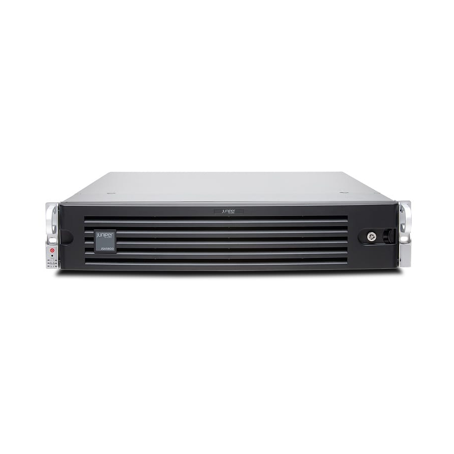
Page 11: Jsa5800 Appliance Front Panel Description
JSA5800 Appliance Front Panel Description Figure 1 on page 5 shows the front panel components of the JSA5800 appliance. Figure 1: JSA5800 Front Panel Table 2 on page 5 lists the front panel components of the JSA5800 appliance. Table 2: JSA5800 Front Panel Components... - Page 12 Provides the colors and states, and the status they indicate. Figure 2 on page 6 shows the front panel LEDs of the JSA5800 appliance. Figure 2: JSA5800 Front Panel LEDs Table 3 on page 7 lists the front panel LEDs of the JSA5800 appliance.
- Page 13 Table 3: JSA5800 Front Panel LEDs Callout LEDs Description Power Solid green—Indicates that the appliance is receiving power. LAN2 When blinking, it indicates DataShare interface activity. Alert/Power fail Red—Indicates a power supply failure. Amber—Indicates that the appliance is operating normally. The LED might glow amber if a rescue configuration is not set.
- Page 14 (Continued) Table 3: JSA5800 Front Panel LEDs Callout LEDs Description Information • Red (blinking)—Indicates a fan failure. • Solid red—Indicates an overheat condition, which might be caused by cables obstructing the airflow in the system or the ambient room temperature being too warm.
-
Page 15: Jsa5800 Appliance Back Panel Description
JSA5800 Appliance Back Panel Description Figure 3 on page 9 shows the back panel components of the JSA5800 appliance. Figure 3: JSA5800 Back Panel Table 4 on page 9 lists the back panel components of the JSA5800 appliance. Table 4: JSA5800 Back Panel Components... - Page 16 Bottom left: port 0; bottom right: port COM port 1 DB-9 COM port. Figure 4 on page 10 shows the back panel Ethernet port LEDs of the JSA5800 appliance. Figure 4: JSA5800 Ethernet Port LEDs Table 5 on page 11 lists the JSA5800 Ethernet port LEDs.
- Page 17 Table 5: JSA5800 Ethernet Port LEDs Callout LEDs Description Link • Off—Indicates no connection or the speed of the connection is 10 Mbps. • Green—Indicates that the speed of the connection is 100 Mbps. • Amber—Indicates that the speed of the connection is 1 Gbps.
-
Page 18: Site Planning, Preparation, And Specifications
C HAPTER Site Planning, Preparation, and Specifications JSA5800 Site Guidelines and Requirements | 13... -
Page 19: Jsa5800 Site Guidelines And Requirements
Additional Hardware Requirements | 17 General Site Installation Guidelines for the JSA5800 Appliance The following precautions can help you plan an acceptable operating environment for your JSA5800 appliance and avoid environmentally caused equipment failures: • For the cooling system to function properly, the airflow around the chassis must be unrestricted. -
Page 20: Jsa5800 Appliance Physical Specifications
JSA5800 Appliance Physical Specifications Table 6 on page 14 lists the hardware specifications for the JSA5800 appliance. Table 6: JSA5800 Appliance Physical Specifications Specification JSA5800 Dimensions (D x W x H) 630 mm x 437 mm x 89 mm (24.8 in. x 17.2 in. x 3.5 in.) Weight 41.9 lb... - Page 21 (Continued) Table 6: JSA5800 Appliance Physical Specifications Specification JSA5800 920 W high-efficiency (94%+) AC-DC power supply Power • AC Input: 100 - 240 V, 50 - 60 Hz, 11 - 4.5 A • DC Output: 4 A @ +5V standby; 75 A @ +12 V 850 W/1010 W high-efficiency redundant DC -DC power supply •...
-
Page 22: Jsa5800 Appliance Rack Requirements
JSA5800 Appliance Description | 0 Additional Hardware Requirements | 0 JSA5800 Appliance Rack Requirements The JSA5800 appliance is installed in a four-post rack. Table 7 on page 16 provides the details of requirements for rack size, clearance, airflow, spacing of mounting brackets and flange holes, and connecting to the building structure. -
Page 23: Additional Hardware Requirements
Rack Requirement Specifications Connecting to the Always secure the rack in which you are installing the JSA5800 appliance to the building structure structure of the building. If your geographical area is subject to earthquakes, bolt the rack to the floor. For maximum stability, also secure the rack to ceiling brackets. -
Page 24: Jsa5800 Appliance Rack Requirements | 0
DNS lookups System security updates from Juniper Networks NTP time synchronizatio SEE ALSO JSA5800 Appliance Rack Requirements | 0 General Site Installation Guidelines for the JSA5800 Appliance | 0 RELATED DOCUMENTATION JSA5800 System Overview | 2... - Page 25 JSA5800 Chassis | 4 JSA5800 Installation Overview | 21...
-
Page 26: Initial Installation And Configuration
C HAPTER Initial Installation and Configuration JSA5800 Installation Overview | 21 Installing the JSA5800 in a Rack | 22 Connecting the JSA5800 to Power | 32 Connecting the JSA5800 Appliance to a Management Device | 35 Configuring the JSA5800 | 36... -
Page 27: Jsa5800 Installation Overview
Tools and Parts Required for Installing the JSA5800 Appliance | 21 Overview of Installing the JSA5800 Appliance in a Rack Installing the JSA5800 The JSA5800 appliance can be installed in a 19-in. four-post rack as described in Appliance Using Front-and-Rear-Mounting Flush to a Rack SEE ALSO... -
Page 28: Installing The Jsa5800 In A Rack
• ESD grounding wrist strap SEE ALSO Overview of Installing the JSA5800 Appliance in a Rack | 0 Installing the JSA5800 Appliance Using Front-and-Rear-Mounting Flush to a Rack | 0 Installing the JSA5800 Appliance | 0 RELATED DOCUMENTATION JSA5800 Site Guidelines and Requirements | 13... -
Page 29: Installing The Jsa5800 Appliance
Installing the 1. Mount the JSA appliance in your server rack using the attached mounting brackets. See JSA5800 Appliance Using Front-and-Rear-Mounting Flush to a Rack 2. Plug the power cords into each of the AC receptacle on the rear panel. See... - Page 30 — 5. Plug a RS-232 (DB-9 F/F) cable into the console port. This cable is a console cable and DB-9 connector with 1-8 pinouts. The connector is shipped with your JSA5800 appliance. Table 10 on page 24 describes the details of DB-9 console port pinouts for the JSA5800 appliance.
- Page 31 (Continued) Table 10: DB-9 Console Connector Pinouts for the JSA5800 Appliance Signal Description DTR Output Data Terminal Ready Chassis Ground DSR Input Data Set Ready RTS Output Request to Send CTS Input Clear to Send Ring Indicator Not Connected 6. Push the power button on the front panel.
-
Page 32: Installing The Jsa5800 Appliance Using Front-And-Rear-Mounting Flush To A Rack
Figure 7: Identifying the Inner, Middle, and Outer Rails Inner rail Outer rail — — Locking tab Locking tab — — Middle rail — To mount the JSA5800 appliance in a four-post rack: 1. Install the inner rail extensions. - Page 33 Secure the inner rails to the chassis with the screws provided. Figure 9: Installing the Inner Rails NOTE: Each inner rail of the JSA5800 appliance has a locking tab. The locking tabs secure the chassis when it is either installed or completely extended from the rack.
- Page 34 b. Insert the front hooks of the outer rails into the front slots of the rack, and use the M5 screws to secure the front of the outer rails to the rack, as shown in Figure 10 on page 28 Figure 11 on page Figure 10: Inserting the Front Mounting Rails...
- Page 35 d. Insert the rear hooks of the outer rails into the rear slots of the rack, and use the screws to secure the rear of the outer rails to the rack, as shown in Figure 11 on page Figure 11: Inserting the Front and Rear Mounting Rails 3.
- Page 36 5. Align the chassis inner rails with the ball-bearing shuttle, as shown in Figure 12 on page Figure 12: Aligning the Chassis Rails with the Ball-Bearing Shuttle 6. With even pressure on both sides, slide the chassis inner rails into the middle rails until the locking tab of the inner rail clicks into the front of the middle rail, locking the chassis into the fully extended position.
- Page 37 Figure 13: Installing the Chassis in a Four-Post Rack SEE ALSO Overview of Installing the JSA5800 Appliance in a Rack | 0 Installing the JSA5800 Appliance Using Front-and-Rear-Mounting Flush to a Rack | 0 Connecting the JSA5800 Appliance to Ground | 0 RELATED DOCUMENTATION...
-
Page 38: Connecting The Jsa5800 To Power
JSA5800 appliance before connecting it to the power source. Grounding for the JSA5800 appliance is provided through the power supply ground. Ensure that you connect the AC power supply module in the appliance to a grounded AC power outlet by using an AC power cord (with the grounding pin) appropriate for your geographical location. - Page 39 2. Connect the black wire to the -48 V terminal block and red wire to the RTN terminal block on the back panel of the JSA5800 appliance. 3. Use the terminal screws to secure the power source cables to the power feed on the JSA5800 appliance.
- Page 40 SEE ALSO Connecting the JSA5800 Appliance to a Management Device Installing the JSA5800 Appliance RELATED DOCUMENTATION JSA5800 Installation Overview | 21 Installing the JSA5800 in a Rack | 22 Configuring the JSA5800 | 36...
-
Page 41: Connecting The Jsa5800 Appliance To A Management Device
Connecting the JSA5800 Appliance to a Management Device You can control the JSA5800 appliance through a connected management device (such as a laptop). Use the console port to connect your laptop as shown in Figure 14 on page Figure 14: Connecting the Management Device... -
Page 42: Configuring The Jsa5800
Installing the JSA5800 Appliance | 23 Configuring the JSA5800 IN THIS SECTION Configuring Basic Settings on the JSA5800 Appliance | 36 Accessing the JSA Interface | 39 Configuring Basic Settings on the JSA5800 Appliance To configure the basic setting using the JSA interface:... - Page 43 NOTE: When using a laptop to connect to the appliance, you must use a terminal program, such as HyperTerminal, to connect to the appliance. At the console prompt, log in as root (default username). No password is required when you log in for the first time.
- Page 44 You are now ready to access JSA. For more information, see 19. Type exit and press Enter. SEE ALSO Accessing the JSA Interface | 0 JSA5800 Appliance Physical Specifications | 0 Connecting the JSA5800 Appliance to a Management Device | 35...
-
Page 45: Accessing The Jsa Interface
IN THIS SECTION Purpose | 39 Action | 39 Purpose To access a Juniper Secure Analytics (JSA) interface: Action 1. Open your Web browser. NOTE: JSA supports the following browsers: • 32-bit Microsoft Internet Explorer, with document mode and browser mode enabled - 8.0 and 9.0... - Page 46 SEE ALSO Configuring Basic Settings on the JSA5800 Appliance | 0 Connecting the JSA5800 Appliance to a Management Device | 35 RELATED DOCUMENTATION JSA5800 Installation Overview | 21 Installing the JSA5800 in a Rack | 22...
-
Page 47: Maintaining Components
C HAPTER Maintaining Components Maintaining the JSA5800 RAID Array | 42 Maintaining JSA5800 Power System | 42... -
Page 48: Maintaining The Jsa5800 Raid Array
• Striping—Split data across more than one disk • Error correction—Redundant data storage to detect and resolve problems The JSA5800 appliance uses the RAID10 configuration. In RAID10, drives are duplicated for fault tolerance. To monitor the JSA5800 RAID array, use the following commands: •... -
Page 49: Maintaining The Jsa5800 Power Supply
Replacing DC Power Supply Cables on the JSA5800 Appliance | 46 Maintaining the JSA5800 Power Supply The JSA5800 appliances ship with redundant AC power supply modules. If one power supply fails, the second power supply takes over for the entire power load. -
Page 50: Replacing An Ac Power Supply On The Jsa5800 Appliance
SEE ALSO Field-Replaceable Units on the JSA5800 Appliance | 0 Replacing AC Power Supply Cables on the JSA5800 Appliance | 0 Contacting Juniper Networks Technical Assistance Center | 49 Replacing AC Power Supply Cables on the JSA5800 Appliance To replace an AC power supply cord: 1. -
Page 51: Replacing A Dc Power Supply On The Jsa5800 Appliance
Make sure the tab on the left edge of the power supply clicks into place. Connecting the JSA5800 to Power 11. To connect the DC source power to the JSA5800 appliance, see... -
Page 52: Replacing Dc Power Supply Cables On The Jsa5800 Appliance
Replacing DC Power Supply Cables on the JSA5800 Appliance To replace a DC power supply cable connected to a JSA5800 appliance: 1. Attach an ESD grounding strap to your bare wrist and connect the strap to one of the ESD points on the chassis. - Page 53 JSA5800 Chassis | 4...
-
Page 54: Troubleshooting Hardware
C HAPTER Troubleshooting Hardware Contacting Juniper Networks Technical Assistance Center | 49... -
Page 55: Contacting Juniper Networks Technical Assistance Center
Contacting Juniper Networks Technical Assistance Center You can contact Juniper Networks Technical Assistance Center (JTAC) 24 hours a day, 7 days a week in one of the following ways: • On the Web, using the Case Manager link at: https:/ /www.juniper.net/support/ •... -
Page 56: Safety And Compliance Information
Warning Statement for Norway and Sweden | 58 Fire Safety Requirements | 59 Installation Instructions Warning | 60 Chassis Lifting Guidelines for the JSA5800 Appliance | 61 Ramp Warning | 61 Rack-Mounting and Cabinet-Mounting Warnings | 62 Grounded Equipment Warning | 66... - Page 57 Multiple Power Supplies Disconnection Warning | 86 TN Power Warning | 87 Agency Approvals for the JSA5800 Appliance | 87 Compliance Statements for EMC Requirements for the JSA5800 Appliance | 89 Compliance Statements for Acoustic Noise for the JSA5800 Appliance | 92...
-
Page 58: Definitions Of Safety Warning Levels
Definitions of Safety Warning Levels Warning formats): The documentation uses the following levels of safety warnings (there are two NOTE: You might find this information helpful in a particular situation, or you might overlook this important information if it was not highlighted in a Note. CAUTION: You need to observe the specified guidelines to prevent minor injury or discomfort to you or severe damage to the device. -
Page 59: General Safety Guidelines And Warnings
Gerät beginnen, seien Sie sich der mit elektrischen Stromkreisen verbundenen Gefahren und der Standardpraktiken zur Vermeidung von Unfällen bewußt. Avvertenza Questo simbolo di avvertenza indica un pericolo. La situazione potrebbe causare infortuni alle persone. Prima di lavorare su qualsiasi apparecchiatura, occorre conoscere i pericoli relativi ai circuiti elettrici ed essere al corrente delle pratiche standard per la prevenzione di incidenti. - Page 60 • Wear safety glasses if you are working under any conditions that could be hazardous to your eyes. • Do not perform any actions that create a potential hazard to people or make the equipment unsafe. • Never attempt to lift an object that is too heavy for one person to handle. •...
-
Page 61: Restricted Access Warning
Restricted Access Warning WARNING: This unit is intended for installation in restricted access areas. A restricted access area is an area to which access can be gained only by service personnel through the use of a special tool, lock and key, or other means of security, and which is controlled by the authority responsible for the location. -
Page 62: Qualified Personnel Warning
que possua uma ferramenta, chave e fechadura especial, ou qualquer outra forma de segurança. Esta área é controlada pela autoridade responsável pelo local. ¡Atención! Esta unidad ha sido diseñada para instalarse en áreas de acceso restringido. Área de acceso restringido significa un área a la que solamente tiene acceso el personal de servicio mediante la utilización de una herramienta especial, cerradura con llave, o algún otro medio de seguridad, y que está... -
Page 63: Prevention Of Electrostatic Discharge Damage
¡Atención! Estos equipos deben ser instalados y reemplazados exclusivamente por personal técnico adecuadamente preparado y capacitado. Varning! Denna utrustning ska endast installeras och bytas ut av utbildad och kvalificerad personal. Prevention of Electrostatic Discharge Damage Device components that are shipped in antistatic bags are sensitive to damage from static electricity. Some components can be impaired by voltages as low as 30 V. -
Page 64: Warning Statement For Norway And Sweden
• When removing or installing a component that is subject to ESD damage, always place it component- side up on an antistatic surface, in an antistatic card rack, or in an antistatic bag (see Figure 15 on page 58). If you are returning a component, place it in an antistatic bag before packing it. Figure 15: Placing a Component into an Antistatic Bag CAUTION: ANSI/TIA/EIA-568 cables such as Category 5e and Category 6 can get electrostatically charged. -
Page 65: Fire Safety Requirements
In addition, you should establish procedures to protect your equipment in the event of a fire emergency. Juniper Networks products should be installed in an environment suitable for electronic equipment. We recommend that fire suppression equipment be available in the event of a fire in the vicinity of the equipment and that all local fire, safety, and electrical codes and ordinances be observed when you install and operate your equipment. -
Page 66: Installation Instructions Warning
NOTE: To keep warranties effective, do not use a dry chemical fire extinguisher to control a fire at or near a Juniper Networks device. If a dry chemical fire extinguisher is used, the unit is no longer eligible for coverage under a service agreement. -
Page 67: Chassis Lifting Guidelines For The Jsa5800 Appliance
Chassis Lifting Guidelines for the JSA5800 Appliance The weight of a fully loaded JSA5800 appliance is approximately 50 lb (22.7 kg). Observe the following guidelines for lifting and moving a JSA5800 appliance: • Before installing the appliance, read the guidelines in General Safety Guidelines and Warnings. -
Page 68: Rack-Mounting And Cabinet-Mounting Warnings
De onderstaande richtlijnen worden verstrekt om uw veiligheid te verzekeren: • De Juniper Networks switch moet in een stellage worden geïnstalleerd die aan een bouwsel is verankerd. • Dit toestel dient onderaan in het rek gemonteerd te worden als het toestel het enige... - Page 69 Les directives ci-dessous sont destinées à assurer la protection du personnel: • Le rack sur lequel est monté le Juniper Networks switch doit être fixé à la structure du bâtiment. • Si cette unité constitue la seule unité montée en casier, elle doit être placée dans le bas.
- Page 70 Le seguenti direttive vengono fornite per garantire la sicurezza personale: • Il Juniper Networks switch deve essere installato in un telaio, il quale deve essere fissato alla struttura dell'edificio. • Questa unità deve venire montata sul fondo del supporto, se si tratta dell'unica unità...
- Page 71 Para garantizar su seguridad, proceda según las siguientes instrucciones: • El Juniper Networks switch debe instalarse en un bastidor fijado a la estructura del edificio. • Colocar el equipo en la parte inferior del bastidor, cuando sea la única unidad en el mismo.
-
Page 72: Grounded Equipment Warning
• Juniper Networks switch måste installeras i en ställning som är förankrad i byggnadens struktur. • Om denna enhet är den enda enheten på ställningen skall den installeras längst ned på ställningen. • Om denna enhet installeras på en delvis fylld ställning skall ställningen fyllas nedifrån och upp, med de tyngsta enheterna längst ned på... -
Page 73: Laser And Led Safety Guidelines And Warnings
Class 1 LED Product Warning | 68 Laser Beam Warning | 69 Juniper Networks devices are equipped with laser transmitters, which are considered a Class 1 Laser Product by the U.S. Food and Drug Administration and are evaluated as a Class 1 Laser Product per EN 60825-1 requirements. - Page 74 LASER WARNING: Unterminated optical connectors can emit invisible laser radiation. The lens in the human eye focuses all the laser power on the retina, so focusing the eye directly on a laser source—even a low-power laser—could permanently damage the eye. Avertissement Les connecteurs à...
- Page 75 Avertissement Alarme de produit LED Class I. Warnung Class 1 LED-Produktwarnung. Avvertenza Avvertenza prodotto LED di Classe 1. Advarsel LED-produkt i klasse 1. Aviso Produto de classe 1 com LED. ¡Atención! Aviso sobre producto LED de Clase 1. Varning! Lysdiodprodukt av klass 1. Laser Beam Warning LASER WARNING: Do not stare into the laser beam or view it directly with optical instruments.
-
Page 76: Radiation From Open Port Apertures Warning
Radiation from Open Port Apertures Warning LASER WARNING: Because invisible radiation might be emitted from the aperture of the port when no fiber cable is connected, avoid exposure to radiation and do not stare into open apertures. Waarschuwing Aangezien onzichtbare straling vanuit de opening van de poort kan komen als er geen fiberkabel aangesloten is, dient blootstelling aan straling en het kijken in open openingen vermeden te worden. -
Page 77: Maintenance And Operational Safety Guidelines And Warnings
Maintenance and Operational Safety Guidelines and Warnings IN THIS SECTION Battery Handling Warning | 71 Jewelry Removal Warning | 72 Lightning Activity Warning | 74 Operating Temperature Warning | 74 Product Disposal Warning | 76 While performing the maintenance activities for devices, observe the following guidelines and warnings: Battery Handling Warning WARNING: Replacing a battery incorrectly might result in an explosion. - Page 78 Warnung Bei Einsetzen einer falschen Batterie besteht Explosionsgefahr. Ersetzen Sie die Batterie nur durch den gleichen oder vom Hersteller empfohlenen Batterietyp. Entsorgen Sie die benutzten Batterien nach den Anweisungen des Herstellers. Advarsel Det kan være fare for eksplosjon hvis batteriet skiftes på feil måte. Skift kun med samme eller tilsvarende type som er anbefalt av produsenten.
- Page 79 kuumenevat, kun ne ovat yhteydessä sähkövirran ja maan kanssa, ja ne voivat aiheuttaa vakavia palovammoja tai hitsata metalliesineet kiinni liitäntänapoihin. Avertissement Avant d'accéder à cet équipement connecté aux lignes électriques, ôter tout bijou (anneaux, colliers et montres compris). Lorsqu'ils sont branchés à l'alimentation et reliés à...
- Page 80 6 in. (15.2 cm) of clearance around the ventilation openings. Waarschuwing Om te voorkomen dat welke switch van de Juniper Networks router dan ook oververhit raakt, dient u deze niet te bedienen op een plaats waar de maximale...
- Page 81 40° C. Para evitar a restrição à circulação de ar, deixe pelo menos um espaço de 15,2 cm à volta das aberturas de ventilação. ¡Atención! Para impedir que un encaminador de la serie Juniper Networks switch se recaliente, no lo haga funcionar en un área en la que se supere la temperatura ambiente máxima recomendada de 40°...
-
Page 82: Action To Take After An Electrical Accident
Product Disposal Warning WARNING: Disposal of this device must be handled according to all national laws and regulations. Waarschuwing Dit produkt dient volgens alle landelijke wetten en voorschriften te worden afgedankt. Varoitus Tämän tuotteen lopullisesta hävittämisestä tulee huolehtia kaikkia valtakunnallisia lakeja ja säännöksiä noudattaen. Avertissement La mise au rebut définitive de ce produit doit être effectuée conformément à... -
Page 83: General Electrical Safety Guidelines And Warnings
General Electrical Safety Guidelines and Warnings WARNING: Certain ports on the device are designed for use as intrabuilding (within- GR-1089-CORE ) the-building) interfaces only (Type 2 or Type 4 ports as described in and require isolation from the exposed outside plant (OSP) cabling. To comply with NEBS requirements and protect against lightning surges and commercial power must not be metallically connected to interfaces disturbances, the intrabuilding ports... -
Page 84: Ac Power Electrical Safety Guidelines
• Canada—Canadian Electrical Code, Part 1, CSA C22.1. • Suitable for installation in Information Technology Rooms in accordance with Article 645 of the National Electrical Code and NFPA 75. Peut être installé dans des salles de matériel de traitement de l’information conformément à l’article 645 du National Electrical Code et à... -
Page 85: Ac Power Disconnection Warning
• AC-powered devices are shipped with a three-wire electrical cord with a grounding-type plug that fits only a grounding-type power outlet. Do not circumvent this safety feature. Equipment grounding must comply with local and national electrical codes. • You must provide an external certified circuit breaker (2-pole circuit breaker or 4-pole circuit breaker based on your device) rated minimum 20 A in the building installation. -
Page 86: Dc Power Electrical Safety Guidelines
Warnung Bevor Sie an einem Chassis oder in der Nähe von Netzgeräten arbeiten, ziehen Sie bei Wechselstromeinheiten das Netzkabel ab bzw. Avvertenza Prima di lavorare su un telaio o intorno ad alimentatori, scollegare il cavo di alimentazione sulle unità CA. Advarsel Før det utføres arbeid på... -
Page 87: Dc Power Disconnection Warning
NOTE: Primary overcurrent protection is provided by the building circuit breaker. This breaker must protect against excess currents, short circuits, and earth grounding faults in accordance with NEC ANSI/NFPA 70. • Ensure that the polarity of the DC input wiring is correct. Under certain conditions, connections with reversed polarity might trip the primary circuit breaker or damage the equipment. - Page 88 verzekeren dat alle stroom UIT is geschakeld, kiest u op het schakelbord de stroomverbreker die het gelijkstroom circuit bedient, draait de stroomverbreker naar de UIT positie en plakt de schakelaarhendel van de stroomverbreker met plakband in de UIT positie vast. Varoitus Varmista, että...
-
Page 89: Dc Power Grounding Requirements And Warning
posición de Apagado (OFF), y sujetar con cinta la palanca del interruptor automático en posición de Apagado (OFF). Varning! Innan du utför någon av följande procedurer måste du kontrollera att strömförsörjningen till likströmskretsen är bruten. Kontrollera att all strömförsörjning är BRUTEN genom att slå... -
Page 90: Dc Power Wiring Sequence Warning
Warnung Der Erdanschluß muß bei der Installation der Einheit immer zuerst hergestellt und zuletzt abgetrennt werden. Avvertenza In fase di installazione dell'unità, eseguire sempre per primo il collegamento a massa e disconnetterlo per ultimo. Advarsel Når enheten installeres, må jordledningen alltid tilkobles først og frakobles sist. Aviso Ao instalar a unidade, a ligação à... - Page 91 Varoitus Oikea yhdistettava kytkentajarjestys on maajohto maajohtoon, +RTN varten +RTN, –40 V varten –60 V. Oikea irrotettava kytkentajarjestys on –40 V varten –60 V, +RTN varten +RTN, maajohto maajohtoon. Attention Câblez l'approvisionnement d'alimentation CC En utilisant les crochets appropriés à l'extrémité de câblage. En reliant la puissance, l'ordre approprié de câblage est rectifié...
-
Page 92: Multiple Power Supplies Disconnection Warning
Varning! Korrekt kopplingssekvens ar jord till jord, +RTN till +RTN, –40 V till –60 V. Korrekt kopplas kopplingssekvens ar –40 V till –60 V, +RTN till +RTN, jord till jord. RELATED DOCUMENTATION General Electrical Safety Guidelines and Warnings | 0 AC Power Electrical Safety Guidelines | 0 DC Power Electrical Safety Guidelines | 80 DC Power Disconnection Warning | 81... -
Page 93: Tn Power Warning
Aviso O dispositivo foi criado para operar com sistemas de corrente TN. ¡Atención! El equipo está diseñado para trabajar con sistemas de alimentación tipo TN. Varning! Enheten är konstruerad för användning tillsammans med elkraftssystem av TN- typ. Agency Approvals for the JSA5800 Appliance JSA5800 comply with the following standards:... - Page 94 • BSMI CNS 13438 and NCC C6357 Taiwan Radiated Emissions • Environmental • Reduction of Hazardous Substances (ROHS) 6 RELATED DOCUMENTATION Compliance Statements for Acoustic Noise for the JSA5800 Appliance | 92 Compliance Statements for EMC Requirements for the JSA5800 Appliance | 89 Installation Instructions Warning | 60...
-
Page 95: Compliance Statements For Emc Requirements For The Jsa5800 Appliance
Korea | 91 United States | 91 FCC Part 15 Statement | 91 This topic describes the EMC requirements for the Juniper Secure Analytics (JSA) 5800 appliance: Canada This Class A digital apparatus complies with Canadian ICES-003. Cet appareil numérique de la classe A est conforme à la norme NMB-003 du Canada. - Page 96 CAUTION: Users should not attempt to make electrical ground connections by themselves, but should contact the appropriate inspection authority or an electrician, as appropriate. Users should ensure for their own protection that the electrical ground connections of the power utility, telephone lines, and internal metallic water pipe system, if present, are connected together.
- Page 97 Korea The preceding translates as follows: This equipment is Industrial (Class A) electromagnetic wave suitability equipment and seller or user should take notice of it, and this equipment is to be used in the places except for home United States The device has been tested and found to comply with the limits for a Class A digital device, pursuant to Part 15 of the FCC Rules.
-
Page 98: Compliance Statements For Acoustic Noise For The Jsa5800 Appliance
• Consult the dealer or an experienced radio or TV technician for help. RELATED DOCUMENTATION Agency Approvals for the JSA5800 Appliance | 87 Compliance Statements for Acoustic Noise for the JSA5800 Appliance | 92 Installation Instructions Warning | 60 Compliance Statements for Acoustic Noise for the JSA5800 Appliance Maschinenlärminformations-Verordnung - 3.
Need help?
Do you have a question about the JSA5800 and is the answer not in the manual?
Questions and answers