
Related Manuals for Juniper JATP700


Summary of Contents for Juniper JATP700
- Page 1 JATP700 Appliance Hardware Guide Modified: 2019-09-10 Copyright © 2019, Juniper Networks, Inc.
- Page 2 END USER LICENSE AGREEMENT The Juniper Networks product that is the subject of this technical documentation consists of (or is intended for use with) Juniper Networks software. Use of such software is subject to the terms and conditions of the End User License Agreement (“EULA”) posted at https://support.juniper.net/support/eula/.
-
Page 3: Table Of Contents
JATP700 Appliance Description ........17... - Page 4 Maintaining the JATP700 RAID Array ........
- Page 5 JATP700 Agency Approvals and Compliance Statements ....84 Agency Approvals for the JATP700 Appliance ......84 Compliance Statements for EMC Requirements for the JATP700 Appliance .
- Page 6 JATP700 Appliance Hardware Guide Copyright © 2019, Juniper Networks, Inc.
- Page 7 Figure 4: JATP700 Ethernet Port LEDs ........
- Page 8 JATP700 Appliance Hardware Guide viii Copyright © 2019, Juniper Networks, Inc.
- Page 9 Table 14: Required Tools and Parts for Installing the JATP700 Appliance ..30 Table 15: Parts List for a JATP700 Appliance ......31...
- Page 10 JATP700 Appliance Hardware Guide Copyright © 2019, Juniper Networks, Inc.
-
Page 11: About The Documentation
® To obtain the most current version of all Juniper Networks technical documentation, see the product documentation page on the Juniper Networks website at https://www.juniper.net/documentation/ If the information in the latest release notes differs from the information in the documentation, follow the product Release Notes. -
Page 12: Table 1: Notice Icons
RFC 1997, BGP Communities Attribute Italic text like this Represents variables (options for which Configure the machine’s domain name: you substitute a value) in commands or [edit] configuration statements. root@# set system domain-name domain-name Copyright © 2019, Juniper Networks, Inc. -
Page 13: Documentation Feedback
We encourage you to provide feedback so that we can improve our documentation. You can use either of the following methods: Online feedback system—Click TechLibrary Feedback, on the lower right of any page on the Juniper Networks TechLibrary site, and do one of the following: Copyright © 2019, Juniper Networks, Inc. xiii... -
Page 14: Requesting Technical Support
Requesting Technical Support Technical product support is available through the Juniper Networks Technical Assistance Center (JTAC). If you are a customer with an active Juniper Care or Partner Support Services support contract, or are covered under warranty, and need post-sales technical support, you can access our tools and resources online or open a case with JTAC. -
Page 15: Creating A Service Request With Jtac
About the Documentation Join and participate in the Juniper Networks Community Forum: https://www.juniper.net/company/communities/ Create a service request online: https://myjuniper.juniper.net To verify service entitlement by product serial number, use our Serial Number Entitlement (SNE) Tool: https://entitlementsearch.juniper.net/entitlementsearch/ Creating a Service Request with JTAC You can create a service request with JTAC on the Web or by telephone. - Page 16 JATP700 Appliance Hardware Guide Copyright © 2019, Juniper Networks, Inc.
-
Page 17: Overview
The appliance can be deployed as a core device, as a Web collector, or as an All-In-One device. The JATP700 appliance is a 2-rack-unit (2-U), rack-mountable chassis with dual AC power supplies (or optional dual DC power supplies), eight hard disk drives that support RAID, 128-GB memory, and two 10-Gigabit Ethernet SFP+ interfaces and four 1-Gigabit Ethernet interfaces. -
Page 18: Jatp700 Appliance Transceiver Interface
JATP700 Appliance Transceiver Interface Two 10-Gigabit Ethernet SFP+ ports on the rear panel of the JATP700 appliance supports SFP+ transceiver. Table 3 on page 18 lists the details of supported transceiver type. -
Page 19: Figure 1: Jatp700 Front Panel
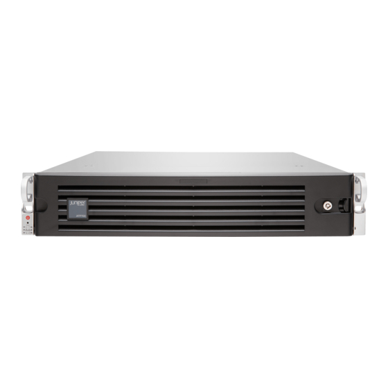
Chapter 1: Overview Figure 1: JATP700 Front Panel Table 4 on page 19 lists the front panel components of the JATP700 appliance. Table 4: JATP700 Front Panel Components Callout Component Description Front Bezel Protects the appliance. Lock Locks the appliance. -
Page 20: Figure 2: Jatp700 Front Panel Leds
JATP700 Appliance Hardware Guide Figure 2: JATP700 Front Panel LEDs Table 5 on page 20 lists the front panel LEDs of the JATP700 appliance. Table 5: JATP700 Front Panel LEDs Callout LEDs Description Power Solid green—Indicates that the appliance is receiving power. - Page 21 Blue (blinking)—Indicates Remote UID is on. Use this function to identify that the server is used from a remote location. Table 6 on page 22 lists the JATP700 hard disk drive port LEDs. Copyright © 2019, Juniper Networks, Inc.
-
Page 22: Jatp700 Appliance Back Panel Description
Blue (blinking)—Indicates the I/O activity. JATP700 Appliance Back Panel Description Figure 3 on page 22 shows the back panel components of the JATP700 appliance. Figure 3: JATP700 Back Panel Table 7 on page 22 lists the back panel components of the JATP700 appliance. -
Page 23: Figure 4: Jatp700 Ethernet Port Leds
1 DB-9 COM port. NOTE: This port is not supported. Figure 4 on page 23 shows the back panel Ethernet port LEDs of the JATP700 appliance. Figure 4: JATP700 Ethernet Port LEDs Table 8 on page 23 lists the JATP700 Ethernet port LEDs. -
Page 24: Table 9: Jatp700 Ipmi Port Leds
10 Gb. Yellow—Indicates that the speed of the connection is 1 Gb. Activity (bottom) Green (blinking)—Indicates link activity. Related JATP700 Site Guidelines and Requirements on page 25 Documentation JATP700 Installation Overview on page 29 Copyright © 2019, Juniper Networks, Inc. -
Page 25: Site Planning, Preparation, And Specifications
JATP700 Site Guidelines and Requirements on page 25 JATP700 Site Guidelines and Requirements General Site Installation Guidelines for the JATP700 Appliance on page 25 JATP700 Appliance Physical Specifications on page 25 JATP700 Appliance Rack and Clearance Requirements on page 27... -
Page 26: Table 11: Jatp700 Appliance Physical Specifications
JATP700 Appliance Hardware Guide Table 11: JATP700 Appliance Physical Specifications Specification JATP700 Dimensions (D x W x H) 630 mm x 437 mm x 89 mm (24.8 in. x 17.2 in. x 3.5 in.) Weight 41.9 lb (19 kg) Warranty... -
Page 27: Jatp700 Appliance Rack And Clearance Requirements
1.25-in. (3.2 cm) apart (top and bottom mounting hole). Connecting to the Always secure the rack in which you are installing the JATP700 appliance building structure to the structure of the building. If your geographical area is subject to earthquakes, bolt the rack to the floor. -
Page 28: Table 13: Required Jatp Ports
JATP700 Appliance Hardware Guide network file system (NFS) file servers (optional) client/server applications (optional) Table 13 on page 28 lists port information for the JATP700 appliance. Table 13: Required JATP Ports Depends on Direction Default Port TCP/UDP Description Internet Configuration... -
Page 29: Initial Installation And Configuration
Configuring the JATP700 on page 40 JATP700 Installation Overview Overview of Installing the JATP700 Appliance in a Rack on page 29 Tools and Parts Required for Installing the JATP700 Appliance on page 29 Overview of Installing the JATP700 Appliance in a Rack You must proceed through the installation process in the following order: Review all safety guidelines and warnings for the JATP700 appliance. -
Page 30: Unpacking The Jatp700
Overview of Unpacking the JATP700 To unpack the JATP700: Gather the tools required to unpack the JATP700. Remove the JATP700 appliance and all items from the shipping container. See, “Unpacking the JATP700” on page Verify that all parts have been received. See, “Unpacking the JATP700”... -
Page 31: Verifying The Jatp700 Parts Received
Verifying the JATP700 Parts Received The JATP700 appliance shipment package contains a packing list. Check the parts in the shipment against the items on the packing list. The packing list specifies the part numbers and carries a brief description of each part in your order. -
Page 32: Installing The Jatp700 In A Rack
JATP700 Appliance Hardware Guide Table 15: Parts List for a JATP700 Appliance (continued) Part Quantity Rail kit 1 set Screws bag Front bezel Related JATP700 Installation Overview on page 29 Documentation Installing the JATP700 in a Rack on page 32... -
Page 33: Figure 6: Sliding And Detaching The Inner Rails
Secure the inner rails to the chassis with the screws provided. Figure 7: Installing the Inner Rails NOTE: Each inner rail of the JATP700 appliance has a locking tab. The locking tabs secure the chassis when it is either installed or completely extended from the rack. -
Page 34: Figure 8: Inserting The Front Mounting Rails
Slide the middle rails away from the rear of the outer rails. Position the ball-bearing shuttle at the front of the middle rails. Align the chassis inner rails with the ball-bearing shuttle, as shown in Figure 10 on page Copyright © 2019, Juniper Networks, Inc. -
Page 35: Figure 10: Aligning The Chassis Rails With The Ball-Bearing Shuttle
Figure 11: Installing the Chassis in a Four-Post Rack Plug each of the power cords into each of the AC receptacles on the rear panel. See Figure 12 on page Copyright © 2019, Juniper Networks, Inc. -
Page 36: Connecting The Jatp700 To Power
Connecting the JATP700 to Power Connecting the JATP700 Appliance to Ground on page 37 Connecting AC Power Source to the JATP700 Appliance on page 37 Connecting DC Power to the JATP700 Appliance on page 38 Powering Off the JATP700 on page 40... -
Page 37: Connecting The Jatp700 Appliance To Ground
Before you connect AC power to the JATP700 appliance: Ensure that you have taken the necessary precautions to prevent electrostatic discharge (ESD) damage. Ensure that you have connected the JATP700 appliance chassis to earth ground, if required by your site guidelines or installation. CAUTION:... -
Page 38: Connecting Dc Power To The Jatp700 Appliance
Before connecting your JATP700 appliance to a DC power source: Ensure that you have taken the necessary precautions to prevent ESD damage. Ensure that you have connected the JATP700 appliance chassis to earth ground, if required by your site guidelines or installation. - Page 39 Both power supply ground terminals and one or both chassis ground terminals You connect a DC power source to the JATP700 appliance by attaching power cables from the external DC power sources to the terminal studs on the DC power feed faceplates.
-
Page 40: Powering Off The Jatp700
Connecting the JATP700 Appliance to a Management Device on page 40 Connecting the JATP700 Appliance to a Management Device You can connect external devices to the JATP700 appliance using the ports on the back panel. To connect a keyboard and monitor to the JATP700 appliance: Connect the end of the keyboard cable to any of the USB ports on the back panel of the appliance. -
Page 41: Selecting The Form Factor
Juniper Networks Advanced Threat Prevention window appears. See Figure 14 on page NOTE: By default, the JATP700 appliance is shipped with the All-In-One configuration. You can change the configuration to your desired form factor by following the instructions from Step to Step 10. -
Page 42: Configuring The Ip Address And Domain Name Servers
(Optional) Type Yes and enter the search domain for the eth0 interface. For example, example.com. NOTE: Provide a space to enter multiple search domains. Type Yes and press Enter to restart the management (eth0) interface. Copyright © 2019, Juniper Networks, Inc. -
Page 43: Configuring The Device Host Name
NOTE: If you decline the self-signed certificate by entering No, the JATP700 appliance will continue to use the existing certificates. These certificates might contain an incorrect hostname or fully qualified domain name (FQDN). To resolve this issue on the Web UI, regenerate a new self-signed SSL certificate or upload your private key and certificate. -
Page 44: Configuring The Alternate Exhaust Interface
Figure 16: Setting Device Basic Attributes Enter the device name. Enter the device description. Enter the device key passphrase. NOTE: You must enclose the special characters white space and \ in double quotation marks. Copyright © 2019, Juniper Networks, Inc. -
Page 45: Accessing The Jatp Interface
Log in to your JATP appliance: https://<IP Address> Where <IP Address> is the IP address of the JATP appliance. Enter the default username admin and the default password juniper. See Figure 17 on page NOTE: Ensure to change the default password after the login. The password must be at least eight characters long. - Page 46 JATP700 Appliance Hardware Guide Installing the JATP700 in a Rack on page 32 Connecting DC Power to the JATP700 Appliance on page 38 Copyright © 2019, Juniper Networks, Inc.
-
Page 47: Maintaining Components
Maintaining the JATP700 Power Supply on page 47 Maintaining the JATP700 Power Supply The JATP700 appliances ship with redundant AC power supply modules. If one power supply fails, the second power supply takes over for the entire power load. NOTE: The JATP700 appliance also supports optional DC power supply modules if you need DC power. - Page 48 Routinely check the power LED on the power supply module. If the LED status is green, the power supply is functioning normally. Periodically inspect the site to ensure that the power cables connected to the JATP700 appliance are securely in place and moisture is not accumulating near the appliance.
-
Page 49: Contacting Customer Support And Returning The Chassis Or
Returning the JATP700 Chassis or Components on page 50 Contacting Juniper Networks Technical Assistance Center You can contact Juniper Networks Technical Assistance Center (JTAC) 24 hours a day, 7 days a week in one of the following ways: On the Web, using the Case Manager link at: https://www.juniper.net/support/... -
Page 50: Returning The Jatp700 Chassis Or Components
The serial number ID of the JATP700 appliance is located on a label on the back of the chassis. You must provide the serial number to the Juniper Networks Technical Assistance Center (JTAC) when you contact them to obtain a Return Materials Authorization (RMA). -
Page 51: Packing A Jatp700 For Shipping
Packing a JATP700 for Shipping To pack a JATP700 appliance for shipping: Power off the JATP700 appliance and remove the AC power cords or DC power cables. Remove the cables that connect the JATP700 appliance to all external devices. Remove the JATP700 appliance from the rack. - Page 52 JATP700 Appliance Hardware Guide Copyright © 2019, Juniper Networks, Inc.
-
Page 53: Safety And Compliance Information
Warning Statement for Norway and Sweden on page 57 Fire Safety Requirements on page 57 Installation Instructions Warning on page 58 Chassis Lifting Guidelines for the JATP700 Appliance on page 59 Restricted Access Warning on page 59 Ramp Warning on page 60... -
Page 54: General Safety Guidelines And Warnings
Some parts of the chassis, including AC and DC power supply surfaces, power supply unit handles, SFB card handles, and fan tray handles might become hot. The following label provides the warning of the hot surfaces on the chassis: Copyright © 2019, Juniper Networks, Inc. -
Page 55: Definitions Of Safety Warning Levels
Avant de travailler sur un équipement, soyez conscient des dangers posés par les circuits électriques et familiarisez-vous avec les procédures couramment utilisées pour éviter les accidents. Copyright © 2019, Juniper Networks, Inc. -
Page 56: Qualified Personnel Warning
Varoitus Ainoastaan koulutettu ja pätevä henkilökunta saa asentaa tai vaihtaa tämän laitteen. Attention Tout installation ou remplacement de l'appareil doit être réalisé par du personnel qualifié et compétent. Warnung Gerät nur von geschultem, qualifiziertem Personal installieren oder auswechseln lassen. Copyright © 2019, Juniper Networks, Inc. -
Page 57: Warning Statement For Norway And Sweden
In addition, you should establish procedures to protect your equipment in the event of a fire emergency. Juniper Networks products should be installed in an environment suitable for electronic equipment. We recommend that fire suppression equipment be available in the event of a fire in the vicinity of the equipment and that all local fire, safety, and electrical codes and ordinances be observed when you install and operate your equipment. -
Page 58: Installation Instructions Warning
To keep warranties effective, do not use a dry chemical fire extinguisher to control a fire at or near a Juniper Networks device. If a dry chemical fire extinguisher is used, the unit is no longer eligible for coverage under a service agreement. -
Page 59: Chassis Lifting Guidelines For The Jatp700 Appliance
Chassis Lifting Guidelines for the JATP700 Appliance The weight of a fully loaded JATP700 appliance is approximately 41.9 lb (19 kg). Observe the following guidelines for lifting and moving a JATP700 appliance: Before installing the appliance, read the guidelines in “JATP700 Site Guidelines and... -
Page 60: Ramp Warning
Ramp Warning WARNING: When installing the device, do not use a ramp inclined at more than 10 degrees. Waarschuwing Gebruik een oprijplaat niet onder een hoek van meer dan 10 graden. Copyright © 2019, Juniper Networks, Inc. -
Page 61: Rack-Mounting And Cabinet-Mounting Warnings
De onderstaande richtlijnen worden verstrekt om uw veiligheid te verzekeren: De Juniper Networks switch moet in een stellage worden geïnstalleerd die aan een bouwsel is verankerd. Dit toestel dient onderaan in het rek gemonteerd te worden als het toestel het enige in het rek is. - Page 62 Les directives ci-dessous sont destinées à assurer la protection du personnel: Le rack sur lequel est monté le Juniper Networks switch doit être fixé à la structure du bâtiment. Si cette unité constitue la seule unité montée en casier, elle doit être placée dans le bas.
- Page 63 Le seguenti direttive vengono fornite per garantire la sicurezza personale: Il Juniper Networks switch deve essere installato in un telaio, il quale deve essere fissato alla struttura dell'edificio. Questa unità deve venire montata sul fondo del supporto, se si tratta dell'unica unità...
- Page 64 Para garantizar su seguridad, proceda según las siguientes instrucciones: El Juniper Networks switch debe instalarse en un bastidor fijado a la estructura del edificio. Colocar el equipo en la parte inferior del bastidor, cuando sea la única unidad en el mismo.
-
Page 65: Grounded Equipment Warning
Varoitus Koska portin aukosta voi emittoitua näkymätöntä säteilyä, kun kuitukaapelia ei ole kytkettynä, vältä säteilylle altistumista äläkä katso avoimiin aukkoihin. Copyright © 2019, Juniper Networks, Inc. -
Page 66: Laser And Led Safety Guidelines And Warnings
öppningar. Laser and LED Safety Guidelines and Warnings Juniper Networks devices are equipped with laser transmitters, which are considered a Class 1 Laser Product by the U.S. Food and Drug Administration and are evaluated as a Class 1 Laser Product per EN 60825-1 requirements. -
Page 67: Class 1 Laser Product Warning
Warnung Class 1 LED-Produktwarnung. Avvertenza Avvertenza prodotto LED di Classe 1. Advarsel LED-produkt i klasse 1. Aviso Produto de classe 1 com LED. ¡Atención! Aviso sobre producto LED de Clase 1. Varning! Lysdiodprodukt av klass 1. Copyright © 2019, Juniper Networks, Inc. -
Page 68: Laser Beam Warning
Operating Temperature Warning on page 71 Product Disposal Warning on page 73 Battery Handling Warning WARNING: Replacing a battery incorrectly might result in an explosion. Replace a battery only with the same or equivalent type recommended by Copyright © 2019, Juniper Networks, Inc. -
Page 69: Jewelry Removal Warning
Följ tillverkarens anvisningar vid kassering av använda batterier. Jewelry Removal Warning WARNING: Before working on equipment that is connected to power lines, remove jewelry, including rings, necklaces, and watches. Metal objects heat Copyright © 2019, Juniper Networks, Inc. - Page 70 (incluidos anillos, collares y relojes). Los objetos de metal se calientan cuando se conectan a la alimentación y a tierra, lo que puede ocasionar quemaduras graves o que los objetos metálicos queden soldados a los bornes. Copyright © 2019, Juniper Networks, Inc.
-
Page 71: Lightning Activity Warning
6 in. (15.2 cm) of clearance around the ventilation openings. Waarschuwing Om te voorkomen dat welke switch van de Juniper Networks router dan ook oververhit raakt, dient u deze niet te bedienen op een plaats... - Page 72 40° C. Ettei ilmanvaihto estyisi, tuuletusaukkojen ympärille on jätettävä ainakin 15,2 cm tilaa. Attention Pour éviter toute surchauffe des routeurs de la gamme Juniper Networks switch, ne l'utilisez pas dans une zone où la température ambiante est supérieure à 40° C. Pour permettre un flot d'air constant, dégagez un espace d'au moins 15,2 cm autour des ouvertures de ventilations.
-
Page 73: Product Disposal Warning
The intrabuilding ports on the device are suitable for connection to intrabuilding or unexposed wiring or cabling only. The addition of primary protectors is not sufficient protection for connecting these interfaces metallically to OSP wiring. Copyright © 2019, Juniper Networks, Inc. -
Page 74: Action To Take After An Electrical Accident
Use caution. Be aware of potentially hazardous conditions that could cause further injury. Disconnect power from the device. If possible, send another person to get medical aid. Otherwise, assess the condition of the victim, then call for help. Copyright © 2019, Juniper Networks, Inc. -
Page 75: Prevention Of Electrostatic Discharge Damage
75). If you are returning a component, place it in an antistatic bag before packing it. Figure 18: Placing a Component into an Antistatic Bag CAUTION ELECTROSTATIC SENSITIVE DEVICES DO NOT OPEN OR HANDLE EXCEPT AT A STATIC-FREE WORKSTATION Copyright © 2019, Juniper Networks, Inc. -
Page 76: Ac Power Electrical Safety Guidelines
To disconnect power, unplug all power cords (one for each power supply). Power Cable Warning (Japanese) WARNING: The attached power cable is only for this product. Do not use the cable for another product. Copyright © 2019, Juniper Networks, Inc. -
Page 77: Ac Power Disconnection Warning
OFF position, and tape the device handle of the circuit breaker in the OFF position. Waarschuwing Voordat u een van de onderstaande procedures uitvoert, dient u te controleren of de stroom naar het gelijkstroom circuit uitgeschakeld Copyright © 2019, Juniper Networks, Inc. - Page 78 Apagado (OFF), y sujetar con cinta la palanca del interruptor automático en posición de Apagado (OFF). Copyright © 2019, Juniper Networks, Inc.
-
Page 79: Dc Power Grounding Requirements And Warning
última a ser desligada. ¡Atención! Al instalar el equipo, conectar la tierra la primera y desconectarla la última. Varning! Vid installation av enheten måste jordledningen alltid anslutas först och kopplas bort sist. Copyright © 2019, Juniper Networks, Inc. -
Page 80: Dc Power Wiring Sequence Warning
–48 V. Al desconectar potencia, la secuencia apropiada del cableado es –48 V a –48 V, +RTN a +RTN, entonces molió para moler. Observe que el alambre de tierra se debe conectar siempre primero y desconectar por último. Copyright © 2019, Juniper Networks, Inc. -
Page 81: Dc Power Wiring Terminations Warning
Abschlüsse sollten die angemessene Größe für die Drähte haben und sowohl die Isolierung als auch den Leiter festklemmen. Avvertenza Quando occorre usare trecce, usare connettori omologati, come quelli a occhiello o a forcella con linguette rivolte verso l'alto. I connettori Copyright © 2019, Juniper Networks, Inc. -
Page 82: Multiple Power Supplies Disconnection Warning
Pour supprimer tout courant électrique de l'unité, tous les cordons d'alimentation doivent être débranchés. Warnung Diese Einheit verfügt über mehr als einen Stromanschluß; um Strom gänzlich von der Einheit fernzuhalten, müssen alle Stromzufuhren abgetrennt sein. Copyright © 2019, Juniper Networks, Inc. -
Page 83: Tn Power Warning
Aviso O dispositivo foi criado para operar com sistemas de corrente TN. ¡Atención! El equipo está diseñado para trabajar con sistemas de alimentación tipo TN. Varning! Enheten är konstruerad för användning tillsammans med elkraftssystem av TN-typ. Copyright © 2019, Juniper Networks, Inc. -
Page 84: Jatp700 Agency Approvals And Compliance Statements
JATP700 Agency Approvals and Compliance Statements Agency Approvals for the JATP700 Appliance on page 84 Compliance Statements for EMC Requirements for the JATP700 Appliance on page 84 Compliance Statements for Acoustic Noise for the JATP700 Appliance on page 87 Agency Approvals for the JATP700 Appliance... -
Page 85: Canada
Japan The preceding translates as follows: This is a Class A device. In a domestic environment this device might cause radio interference, in which case the user needs to take adequate measures. VCCI-A Copyright © 2019, Juniper Networks, Inc. -
Page 86: Korea
Increase the separation between the equipment and the receiver. Connect the equipment into an outlet on a circuit different from that to which the receiver is connected. Consult the dealer or an experienced radio or TV technician for help. Copyright © 2019, Juniper Networks, Inc. -
Page 87: Compliance Statements For Acoustic Noise For The Jatp700 Appliance
Chapter 6: Safety and Compliance Information Compliance Statements for Acoustic Noise for the JATP700 Appliance The maximum emitted sound pressure level is 70 dB(A) or less per EN ISO 7779. German Translation: Maschinenlärminformations-Verordnung - 3. GPSGV, der höchste Schalldruckpegel beträgt 70 dB(A) oder weniger gemäss EN ISO 7779. - Page 88 JATP700 Appliance Hardware Guide Copyright © 2019, Juniper Networks, Inc.
Need help?
Do you have a question about the JATP700 and is the answer not in the manual?
Questions and answers