Table of Contents
Advertisement
Quick Links
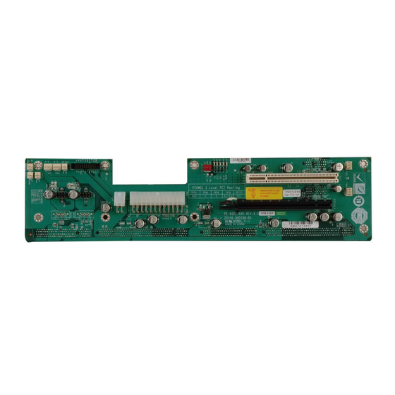
5-Slot PICMG 1.3 PCIe to PCI Bridge Backplane
1. USB1, USB2: External 4 Port USB Connectors From the Mainboard
7
5
3
● ● ● ■
● ● ● ●
8
6
4
2. FAN1, FAN2, FAN3, FAN4 : Fan Connector
3. ATXCTL1 : Backplane to Mainboard ATX Power Control Connector
3
4. PWRBTN : Power On Button
5. RESET : Reset Button Connector
2
1
PE-6SD2-R40
User Manual Ver. 4.0
PIN DESCRIPTION PIN DESCRIPTION
1
1
3
5
2
7
PIN
3
2
1
2
1
PIN
●
2
1
■
1
2
PIN
●
1
■
2
USBVCC
DATA-
DATA+
GND
DESCRIPTION
1
GND
2
+12V
3
NC
PIN
DESCRIPTION
1
GND
2
PSON#
3
5VSB
DESCRIPTION
GND
PWRBT#
DESCRIPTION
GND
SHB_RST#
Nov. 16, 2007
2
GND
4
DATA+
6
DATA-
8
USBVCC
1
Advertisement
Table of Contents

Related Manuals for IEI Technology PE-6SD2-R40


Summary of Contents for IEI Technology PE-6SD2-R40
- Page 1 Nov. 16, 2007 PE-6SD2-R40 5-Slot PICMG 1.3 PCIe to PCI Bridge Backplane User Manual Ver. 4.0 1. USB1, USB2: External 4 Port USB Connectors From the Mainboard PIN DESCRIPTION PIN DESCRIPTION USBVCC ● ● ● ■ DATA- DATA+ ● ● ● ●...
- Page 2 6. PWRGD : Power Good Connector DESCRIPTION ● ■ PWRGD 7. SM-BUS : System Management BUS Connector DESCRIPTION ● SMDAT ■ SMCLK 8. CN1 : PCIE X16 SDVO Control Signal Pin DESCRIPTION EXP_EN ■ ● ● SDVO_CLK SDVO_DAT 9. IOPWR : The I/O Power Connector indicators for controlling your CPU board DESCRIPTION DESCRIPTION...
- Page 3 10. PCI routing table: 11. Notice: a. Recommend to use 6mm width spacer to install b. Torsion must less than 6lb-inch...
- Page 4 12. Dimension:...
Need help?
Do you have a question about the PE-6SD2-R40 and is the answer not in the manual?
Questions and answers