Table of Contents
Advertisement
Quick Links
Operation
Supply Systems
Used to transfer medium to high viscosity sealants and adhesive materials, at ambient
temperature, out of various sized material shipping containers. For professional use only.
S20 3 inch single post
20 liter (5 gallon)
125 psi (0.9 MPa, 9 bar) Maximum Air Inlet Pressure
D60 3 inch dual post
60 liter (16 gallon), 30 liter (8 gallon), 20 liter (5 gallon)
150 psi (1.0 MPa, 10 bar) Maximum Air Inlet Pressure
D200 3 inch dual post
200 liter (55 gallon), 115 liter (30 gallon), 60 liter (16
gallon), 30 liter (8 gallon), 20 liter (5 gallon)
150 psi (1.0 MPa, 10 bar) Maximum Air Inlet Pressure
D200s 6.5 inch dual post
200 liter (55 gallon), 115 liter (30 gallon)
125 psi (0.9 MPa, 9 bar) Maximum Air Inlet Pressure
See page 4 for model information and approvals.
Important Safety Instructions
Read all warnings and instructions in this
manual before using the equipment.
Save these instructions.
313526S
D200
Model CM14BA
EN
ti10429a
Advertisement
Table of Contents

Related Manuals for Graco S20


Summary of Contents for Graco S20
- Page 1 Used to transfer medium to high viscosity sealants and adhesive materials, at ambient temperature, out of various sized material shipping containers. For professional use only. S20 3 inch single post 20 liter (5 gallon) 125 psi (0.9 MPa, 9 bar) Maximum Air Inlet Pressure...
-
Page 2: Table Of Contents
California Proposition 65 ....45 Graco Standard Warranty....46... -
Page 3: Related Manuals
Related Manuals Related Manuals Manual in Manual in Description Description English English 312491 Pump Fluid Purge Kit Supply Systems 312492 Drum Roller Kit Instruction 313527 Supply Systems Repair-Parts 312493 Light Tower Kit Instruction 313528 Tandem Supply Systems Operation 406681 Platen Cover Kit 313529 Tandem Supply Systems Repair-Parts 334048... -
Page 4: Models
To order replacement parts, see the Parts section in the Supply Systems Repair-Parts manual. The digits in the matrix on the next page do not D200 and D200s Models correspond to the Ref. Nos. in the Parts drawings and lists. D60 Models S20 Models 313526S... - Page 5 Models First and Third and Sixth Digit Second Digit Fourth Digit Fifth Digit Platen and Seal Options Ram Options Platen Platen Seal Model DataTrak Platen Size Style Material Material Pump Code Size Name Voltage Air Controls (See Table 1 3 in. S20c no volt 20 L (5 Gal)
-
Page 6: Pump Identification
Models Pump Identification See the Check-Mate, Dura-Flo, or NXT Pump Packages Instruction-Parts manual or the ID plate on the pump to determine the pump part number. The pump identification code listed in each table represents the air motor series, nominal air motor size (cc), pump series, pump displacement (cc), and pump material of construction. - Page 7 Models Table 2: Check-Mate Pump Identification Code/Part No. Index Pump Pump Part (see Pump Pump Part (see Pump Pump Part (see Pump Pump Part (see Code manual 312376) Code manual 312376) Code manual 312376) Code manual 312376) NXT 1800/CM 60 NXT 2200/CM 200 NXT 6500/CM 250 NXT 200/CM 60...
-
Page 8: Warnings
Warnings Warnings The following warnings are for the setup, use, grounding, maintenance, and repair of this equipment. The exclamation point symbol alerts you to a general warning and the hazard symbols refer to procedure-specific risks. When these symbols appear in the body of this manual or on warning labels, refer back to these Warnings. Product-specific hazard symbols and warnings not covered in this section may appear throughout the body of this manual where applicable. - Page 9 Warnings WARNING FIRE AND EXPLOSION HAZARD Flammable fumes, such as solvent and paint fumes, in work area can ignite or explode. Paint or solvent flowing through the equipment can cause static sparking. To help prevent fire and explosion: • Use equipment only in well-ventilated area. •...
- Page 10 Warnings WARNING SPLATTER HAZARD Hot or toxic fluid can cause serious injury if splashed in the eyes or on skin. During blow off of platen, splatter may occur. • Use minimum air pressure when removing platen from drum. TOXIC FLUID OR FUMES HAZARD Toxic fluids or fumes can cause serious injury or death if splashed in the eyes or on skin, inhaled, or swallowed.
-
Page 11: Component Identification
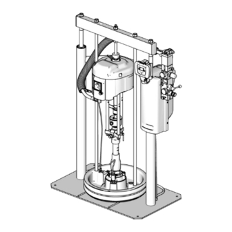
Component Identification Component Identification D200 3 in. and D200s 6.5 in. Dual Post Model CM14BA Shown (Note: Do not use the air motor lift ring to lift the entire system.) Lift Locations TI10430a . 1: Typical Installation Key: Ram Assembly Platen Lift Rod Air Motor Pump Bleed Valve... -
Page 12: S20 3 In. Single Post And D60 3 In. Dual Post
Component Identification S20 3 in. Single Post and D60 3 in. Dual Post Model CM2MRY Shown Model CM9HLB Shown (Note: Do not use the air motor lift ring to lift the entire system.) Lift Location Lift Location Lift Location (not shown) -
Page 13: Integrated Air Controls (G)
Component Identification Integrated Air Controls (G) See Basic Supply System Operating Controls on page 19 for more information on the Integrated Air Controls, which include: • Main air slider valve (BA): turns air on and off to the supply system. When closed, the valve relieves pressure downstream. -
Page 14: Air Line Accessories
Component Identification Air Line Accessories 2-Button Interlock Air Controls Accessory See F . 1. The two button interlock accessory requires the • Air line drain valve (U): Not supplied operator to use both hands to raise, or lower the ram while the platen is outside the drum. -
Page 15: Installation
Connect other end of wire to a true earth ground. See in the text refer to the callouts in the figures. . 6. Accessories are available from Graco. Make certain all accessories are adequately sized and pressure-rated to meet the system’s requirements. -
Page 16: Mechanical Setup
1. Fill displacement pump wet cup (R) 1/3 full with into a properly grounded electrical outlet. Use a zip tie, Graco Throat Seal Liquid (TSL). if needed, to secure power cord in place. 2. Back-off air regulators to their full counterclockwise position and close all shutoff valves. -
Page 17: Attach And Adjust Drum Low/Empty Sensor (Optional)
. 9. 2. Attach low/empty sensor bracket (EA) to mounting bracket (EB). c. For S20 supply systems: Attach the actuator (ED) to the ram cylinder endcap, so the sensor (EE) passes in front of the bracket (ED) at the correct level for drum low or drum empty. See . -
Page 18: Attach Drum Stops
Installation Attach Drum Stops Only D200s, D200, and D60 Supply systems are 1. Locate the correct set of mounting holes on the ram shipped with drum stops in place to help position the base. drum on the ram. For replacement parts, order Kit 2. -
Page 19: Supply System Overview
Supply System Overview Supply System Overview Basic Supply System Operating The ram director valve (BC) is used to raise and lower the ram. Moving the director valve handle to UP will Controls raise the ram, and moving the director valve handle to DOWN will lower the ram. - Page 20 Supply System Overview Blowoff Button (BG) Blowoff air will vent between the platen (D) and the drum when the platen exits the drum, causing noise and potential material splatter. Wear appropriate protective equipment to help prevent serious injury from potential material splatter when the platen exits the drum.
-
Page 21: Operation
Operation Operation Pressure Relief Procedure Follow the Pressure Relief Procedure whenever you see this symbol. This equipment stays pressurized until pressure is manually relieved. To help prevent serious injury from pressurized fluid, such as skin injection, splashing fluid and moving parts, follow the Pressure Relief . -
Page 22: Start And Adjust Ram
Operation Ram Pressure Relief Moving parts can pinch or amputate fingers. When the pump is operating, and when raising or lowering The ram may raise or lower in sudden, jerky, start and the ram, keep fingers and hands away from the stop movements. - Page 23 11. Replace the drum cover before moving the drum to prevent possible spillage. . 18: S20 and D60 3 in. Single Post 12. Put a full drum of material on the ram base, slide it back against the drum stops, and center it under the platen (D).
-
Page 24: Start And Adjust Pump
Operation 16. Verify the platen (D) and material drum are properly model specific instructions, care of the pump, aligned. Adjust the position of the drum if preventative maintenance, troubleshooting, and necessary. accessory equipment. See Related Manuals on page 17. Set the director valve (BC) to DOWN and lower the ram until fluid appears at the top of the platen bleed 1. -
Page 25: Change Drums
Operation 10. Gradually turn the air motor regulator (BE) press the prime/flush key (PF). See Remote clockwise until the pump begins to cycle. DataTrak Controls and Indicators on page 28. 11. Allow material to flow into the cup until there is a 19. - Page 26 Operation platen, causing blowoff air to escape between 10. Inspect the platen (D) and, if necessary, remove any remaining material or material build–up. the platen and drum, move the ram director valve (BC) to the DOWN position to begin 11. Follow the procedure to Load Drums on page 22. lowering the ram until the drum makes contact and realigns with the ram base.
-
Page 27: Shutdown Of The Pump
Operation Shutdown of the Pump Follow the Pressure Relief Procedure on page 21. Remote DataTrak Setup The remote DataTrak display unit comes fully assembled. Use the following instructions and figures to connect the remote DataTrak to the supply system. The system requires either 100-240 Vac, 50/60 Hz input, or 24 Vdc to the power supply. -
Page 28: Remote Datatrak Controls And Indicators
Remote DataTrak Controls and Indicators Remote DataTrak Controls and Indicators Run Mode MC/MS Setup Mode ti10249A SC; See Details at right. . 24: Remote DataTrak Controls and Indicators Key: PF Prime/Flush Key SC Display Screen LE LED (diagnostic indicator when lit) RK Reset/Cancel Key (also used to scroll) Flow Rate Units, user settable to: CF Cycle/Flow Rate... -
Page 29: Remote Datatrak Operation
Remote DataTrak Operation Remote DataTrak Operation NOTICE To prevent damage to soft key buttons, do not press the buttons with sharp objects such as pens, plastic cards, or fingernails. Startup 1. Perform the Start and Adjust Ram procedure on . 26: Splash Screen page 22, and the Start and Adjust Pump procedure on page 24. -
Page 30: Prime Mode
Remote DataTrak Operation Prime Mode Password Screen If a password has been assigned (not set to ‘0000’), the 1. Press to enter Prime Mode screen. The Prime Password screen will appear (F . 29). Enter the password to access the Setup screens. symbol (PS) will appear in the display and the LED (LE) will flash. - Page 31 Remote DataTrak Operation Runaway Cycle Rate/Enable Runaway Protection NOTE: Graco recommends setting runaway cycle rate (RS) to 60 or less. Choose a value that is just above the maximum cycle rate of the application. NOTE: When runaway protection is enabled (RT), a ✓...
- Page 32 Remote DataTrak Operation Setup Screen 3 4. See page 34 for a description of E1, E2, and E4 diagnostic codes. Setup screen 3 displays a non-resettable grand total counter (GT) at the top. Use Setup screen 3 to set the NOTE: When E1, E2, and E4 diagnostic options are password (PW), assign a time limit for the screensaver enabled, a ✓...
-
Page 33: Diagnostic Mode
Remote DataTrak Operation Diagnostic Mode b. Press and release to scroll to the Runaway Diagnostic screen, or return to the previous Run screen if no other Diagnostic screens are Diagnostics active. Remote DataTrak can diagnose several problems with the supply system. When the monitor detects a problem, the LED (B) will flash and a diagnostic code will appear on the display. - Page 34 Remote DataTrak Operation Diving Up Diagnostic Code Screen Diving Down Diagnostic Code Screen See F . 34. If the pump shows diving up symptoms See F . 35. If the pump shows diving down symptoms and the E1 Diagnostic Code is enabled, the Diving Up and the E2 Diagnostic Code is enabled, the Diving screen becomes active.
- Page 35 Remote DataTrak Operation Disconnected Solenoid Diagnostic Code Drum Low/Empty Diagnostic Code Screen Screen See F . 37 and F . 38. If the drum low/empty sensor trips, the Drum Low or Drum Empty screen becomes See F . 36. If the system detects a disconnected air active, depending on which sensor setting is chosen.
- Page 36 Remote DataTrak Operation Reed Switch Diagnostic Code Screen Maintenance Counter Expired Screen If the system detects an air motor reed switch error, the If the system has counted down to 0 from the setpoint Reed Switch Diagnostic screen becomes active. for number of cycles/gallons/liters, the Maintenance Counter Expired Screen becomes active.
- Page 37 Remote DataTrak Operation Table 4: Diagnostic Codes Accessory Light Flash Tower Symbol Code Code Name Diagnosis Cause Code* Code Runaway Pump running faster than • Increased air Red Solid set runaway limit. pressure. • Increased fluid output. • Exhausted fluid supply.
-
Page 38: Troubleshooting
Troubleshooting Troubleshooting Check all possible problems before disassembling the ram, pump, or platen. If equipped with a DataTrak, refer to the descriptions of DataTrak diagnostic codes on page 37. Refer to the Check-Mate, Dura-Flo, or NXT Pump Packages Instruction-Parts manual for pump troubleshooting and additional diagnostics. Problem Cause Solution... -
Page 39: Dimensions
Dimensions Dimensions D200 (ram up) (ram up) (ram down) (ram down) ti10429a r_255648_313527_5a (NXT) (ram up) (ram up) (ram down) (ram down) r_255648_313527_6a . 41: Dimensions 313526S... -
Page 40: Dimensions
G Diameter Ram Model in. (mm) in. (mm) in. (mm) in. (mm) in. (mm) in. (mm) in. (mm) S20 (NXT) 84 (2133.6) 59 (1498.6) 16 (406.4) 19 (482.6) 11 (279.4) 15 (381) 4 x 0.56 (14.2) 59.3 (1506) 35.8 (909) 16 (406.4) -
Page 41: Schematics
Schematics Schematics Remote DataTrak, Light Tower, Drum Low/Empty Sensor . 42: Schematics 313526S... -
Page 42: Recycling And Disposal
Recycling and Disposal Recycling and Disposal End of Product Life At the end of the product’s useful life, dismantle and recycle it in a responsible manner. • Perform the Pressure Relief Procedure. • Drain and dispose of fluids according to applicable regulations. - Page 43 Recycling and Disposal 313526S...
-
Page 44: Technical Specifications
Check-Mate Elite Series displacement pumps See manual 3A8564 Maximum air input pressure (supply system) S20 - 3 in. single post, 5 gal. (20L) 125 psi (0.9 MPa, 9 bar) D60 - 3 in. dual post, 5 gal. (20L), 16 gal. (60L), 150 psi (1.0 MPa, 10 bar) -
Page 45: California Proposition 65
Technical Specifications Supply Systems Metric Materials of construction (platen) (See Models on page 5 for platen and seal option codes) B : 257727, 5 gal. (20 L) Electroless nickel, polyurethane, nitrile, carbon steel, J : 257732, 8 gal. (30 L) polyethylene, zinc plated carbon steel, buna, 316 sst, S : 257737, 16gal. -
Page 46: Graco Standard Warranty
With the exception of any special, extended, or limited warranty published by Graco, Graco will, for a period of twelve months from the date of sale, repair or replace any part of the equipment determined by Graco to be defective.
Need help?
Do you have a question about the S20 and is the answer not in the manual?
Questions and answers