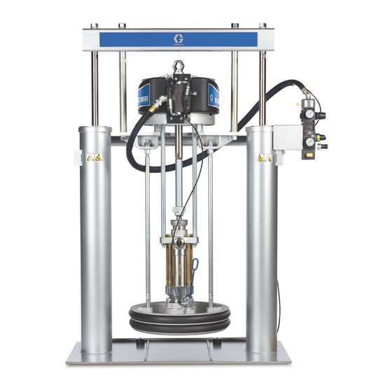
Graco D200 Repair Manual
Supply systems
Hide thumbs
Also See for D200:
- Instructions manual (84 pages) ,
- Instructions-parts list manual (28 pages) ,
- Operation (46 pages)
Table of Contents
Advertisement
Repair - Parts
Supply Systems
For transferring or dispensing sealants, adhesives, or other medium to high viscosity
fluids. For professional use only.
Not approved for use in European explosive atmosphere locations.
L20c 2 inch single post elevator
20 liter (5 gallon) size
100 psi (0.7 MPa, 7 bar) Maximum Air Inlet Pressure
S20 3 inch single post
20 liter (5 gallon) size
125 psi (0.9 MPa, 9 bar) Maximum Air Inlet Pressure
D60 3 inch dual post
60 liter (16 gallon) size
150 psi (1.0 MPa, 10 bar) Maximum Air Inlet Pressure
D200 3 inch dual post
200 liter (55 gallon), 115 liter (30 gallon),
60 liter (16 gallon) size, 30 liter (8 gallon),
20 liter (5 gallon) sizes
150 psi (1.0 MPa, 10 bar) Maximum Air Inlet Pressure
D200S 6.5 inch dual post
200 liter (55 gallon), 115 liter (30 gallon)
125 psi (0.9 MPa, 9 bar) Maximum Air Inlet Pressure
Important Safety Instructions
Read all warnings and instructions in this manual.
Save these instructions.
See page 6 for model information and approvals.
The Graco Control Architecture Electric Components
are Listed in Intertek's Directory of Listed Products.
D200
CM14BA
313527ZAD
EN
Ti10429A
Advertisement
Chapters
Table of Contents

Related Manuals for Graco D200


Summary of Contents for Graco D200
- Page 1 D60 3 inch dual post 60 liter (16 gallon) size 150 psi (1.0 MPa, 10 bar) Maximum Air Inlet Pressure D200 3 inch dual post 200 liter (55 gallon), 115 liter (30 gallon), 60 liter (16 gallon) size, 30 liter (8 gallon), 20 liter (5 gallon) sizes 150 psi (1.0 MPa, 10 bar) Maximum Air Inlet Pressure...
-
Page 2: Table Of Contents
D200s 6.5 in. Supply Units ....39 D200 3 in. Supply Units ....41 D200s and D200 Pump Mounts for 55 Gallon (200 Liter) Platen . -
Page 3: Related Manuals
Related Manuals Related Manuals The following manuals are available at www.graco.com. Component manuals in English: Manual Description 313526 Supply Systems Operation 313528 Tandem Supply Systems Operation 313529 Tandem Supply Systems Repair-Parts ® Check-Mate Displacement Pumps 312375 Instructions-Parts ® Check-Mate Pump Packages... -
Page 4: Warnings
Warnings Warnings WARNING SKIN INJECTION HAZARD High-pressure fluid from gun, hose leaks, or ruptured components will pierce skin. This may look like just a cut, but it is a serious injury that can result in amputation. Get immediate surgical treatment. •... - Page 5 Warnings WARNING ELECTRIC SHOCK HAZARD This equipment must be grounded. Improper grounding, setup, or usage of the system can cause elec- tric shock. • Turn off and disconnect power cord before servicing equipment. • Use only grounded electrical outlets. • Use only 3-wire extension cords.
-
Page 6: Models
Models Models Check the identification plate (ID) for the 6-digit part number of the supply system. Use the following matrix to define the construction of the supply system, based on the six digits. For example, Part No. CM14BA represents a ®... - Page 7 F, SW coated 20 L 3 in. no volt (5 Gal) F, DW Nitrile 20 L Polyure- 3 in. D200 no volt (5 Gal) F, DW thane (See Table 2 (Supply 2-Button 30 L for 2-digit System with 3 in...
- Page 8 Models Table 1: Check-Mate Pump Code/Part No. Index Pump Part No. Pump Part No. Pump Part No. Pump Part No. Pump (see manual Pump (see manual Pump (see manual Pump (see manual Code 312376) Code 312376) Code 312376) Code 312376) P38SCS NXT 2200/CM 200 NXT 6500/CM 250...
- Page 9 Models Table 2: Dura-Flo Pump Identification Code/Part No. Index Pump Part No. Pump Part No. Pump Part No. Pump Part No. Pump (see manual Pump (see manual Pump (see manual Pump (see manual Code 311826) Code 311826) Code 311833) Code 311828) NXT 3400/DF 430CS NXT 6500/DF 580CS...
-
Page 10: Component Identification
Component Identification Component Identification D200 3 in. and D200s 6.5 in. Dual Post CM14BA Model Shown Lift Locations (Note: Do not use motor lift ring to lift entire system.) TI10430a Key: Ram Assembly Platen Lift Rod Air Motor Pump Bleed Valve... -
Page 11: S20 3 In. Single Post And D60 3 In. Dual Post
Component Identification S20 3 in. Single Post and D60 3 in. Dual Post (Note: Do not use motor Model CM9HLB Shown Model CM2MRY Shown lift ring to lift entire system.) Lift Location Lift Location Lift Location r_255648_313527_5a r_255648_313527_6a Key: Ram Assembly Air Filter (not supplied, see F . -
Page 12: Integrated Air Control Module
Component Identification Integrated Air Control Module Integrated Air Line Accessories D200, D200s, D60, and S20 Models See F . 1. The integrated air controls include: • Air line drain valve (U) • Main air slider valve (BA): turns air on and off to the system. -
Page 13: L20C 2In. Elevator
Component Identification L20c 2in. Elevator CM7B1G Model Shown Lift Location r_257302_312376_1e Key: BA Elevator Cart BB Air Motor BC Displacement Pump BD Platen BF Elevator and Pump Air Controls Platen Bleed Port Pump Bleed Valve Enclosed Wet Cup (behind air controls) 313527ZAD... -
Page 14: L20C 2 In. Air Controls
Component Identification L20c 2 in. Air Controls • Air motor regulator (DA): Controls air pressure to motor. • Blowoff button (DB): turns air on and off to push the platen out of an empty drum. • Air motor shutoff valve (DC): turns air on and off to the air motor. -
Page 15: Platen Component Identification
Component Identification Platen Component Identification Model 255664, 200 liter (55 gallon) Model 257727, 20 liter (5 gallon) TI10518A r_255648_313527_7a Key: EA Plate EB Wipers EG Spacer EH Cap Screws EJ Clamps EK Bleed Handle EL Bleed Valve EM Air Assist Body Check Valve EN Wiper Plate (under wiper) EP O-ring Seal 313527ZAD... -
Page 16: Before Beginning Repair
2. For D200s, D200, S20, and D60 Air Controls: See static build up or in the event of a short circuit. -
Page 17: Flush Before Using Equipment
Maintenance Procedures Flush Before Using Equipment Adjust Spacers The pump was tested with lightweight oil, which is left in Use Platen with Tapered and Straight Sided the fluid passages to protect parts. To avoid contaminat- Pails ing your fluid with oil, flush the pump with a compatible solvent before use. -
Page 18: Remove And Reinstall Wipers
Maintenance Procedures Use platen with straight sided pail Remove and Reinstall Wipers 1. Ensure large diameter of spacer (EG) is facing Disassemble 20, 30, and 60 Liter Wiper down. Work spacer (EG) up over the platen by Assemblies hand completely above the flange of the platen. See . - Page 19 Maintenance Procedures Reassemble 20, 30, and 60 Liter Wiper c. For double wiper assemblies: Place bottom Assemblies plate (455) on flat surface. Place wiper support (454), wiper (453), spacer (452), wiper (453) 1. Assemble wiper assembly. and top plate (457) on bottom plate (455). a.
- Page 20 Maintenance Procedures Remove 30 and 55 Gallon Platen Wipers Remove 55 Gallon Platen Hose Wipers 1. To replace worn or damaged wipers (EB), raise 1. To replace worn or damaged wipers (EB), raise platen up out of drum. Remove drum from base. platen up out of drum.
- Page 21 Maintenance Procedures 3. Insert jack screw end of band (410) into hose (408 4. Lubricate outside of hoses (408,409) and place on or 409) and push completely through hose. upper or lower groove on plate. Adjust hose and band so that the angled ends of hose press against 408, 409 each other.
-
Page 22: Troubleshooting
Troubleshooting Troubleshooting Check all possible problems before disassembling the ram, pump, or platen. Refer to Supply Unit Operation man- ual 313526 for descriptions of DataTrak diagnostic codes. Refer to Check-Mate Pump Packages manual 312376 for pump troubleshooting. Problem Cause Solution Ram will not raise or lower. -
Page 23: Repair
Repair Repair Disconnect Pump from Platen 20, 30, and 60 Liter Platen 1. Loosen two 5/16 in. screws (462) from platen. The pump is mounted to the platens by mounting kit 255392 or 257630. See the Repair Kits on page 64. 2. -
Page 24: Connect Platen
Before installing the 20, 30, or 60 liter platen to a be removed, see page 27. pump with an intake adapter, install adapter and o-ring from mounting kit 257630 using the two set D200 3 in. and D200s 6.5 in. Supply Units screws. See F . 19. NXT Air Motors: 1. - Page 25 Repair b. For NXT 200-1800 with 55 gallon platen: Go to step 3. c. For NXT with smaller platens and all supply units: See procedure for D60 3 in. Dual Post, S20 3 in. Single Post, and L20c 2 in. Supply Units.
-
Page 26: Install Displacement Pump
4. Connect air motor: a. For NXT 2200-6500 with 55 gallon platen: Use D200 3 in. and D200s 6.5 in. Supply Units wrench on nut (105) on top of ram bar to lower air motor onto displacement pump. See F . -
Page 27: Remove Air Motor
. 25: NXT 200-1800 with 55 Gallon PLaten 3. Disconnect air motor: c. For NXT with smaller platen (D200 3 in., D200s a. For NXT 2200-6500 with 55 gallon platen (D200 6.5 in., and D60 3 in. supply units): Remove 3 in. - Page 28 Repair d. For NXT on S20 3 in. supply unit and L20c 2 in. elevator: Remove screws (111) and washers 103, 102 (110) securing motor to mounting bracket. TI10658A . 29: Xtreme XL Air Motors r_255648_313527_10a . 28 4. Using a capable hoist, secure air motor to hoist and remove air motor.
-
Page 29: Install Air Motor
(111) and washers (110). See . 25 on page 27. D200 3 in. and D200s 6.5 in. Supply Units 3. Connect air hose to motor. If using a remote Data- Trak, connect electrical connections to the air NXT with 55 gallon platen: motor. - Page 30 Repair D60 3 in. Dual Post Supply Unit NXT Air Motors 1. Using a secure hoist, attach motor to mounting plate (109) with screws (111) and washers (110). See . 27 on page 27. 2. See Reconnect Displacement Pump in Check-Mate Pump Packages manual 312376.
-
Page 31: Supply Unit Repair
Repair Supply Unit Repair To reduce the risk of serious injury whenever you are instructed to relieve pressure always follow the Pres- sure Relief Procedure on page 16. Do not use pres- surized air to remove the guide sleeve or the piston. D200s 6.5 in. - Page 32 Repair Disassemble Ram Piston Assemble Ram Piston 1. Relieve pressure. 1. Install new o-rings (1p, 1j) on piston rod (1d) and piston (1r). Lubricate the piston (1r) and o-rings (1p, 2. Remove nuts (1a) and lockwashers (1b) holding the 1j). Reinstall piston (1r) and lower retaining ring (1n) tie bar (1c) to the piston rods (1d).
- Page 33 3. Remove retaining ring (203, 803). 802b 802d 4. Remove piston rod seal and bearing. 802c a. For D200 and D60 3 in. Rams: Slide end cap 802j (202a), pin (202b), o-ring (202c), and spring 802a (202m) up off of the piston rod (202n). Remove...
- Page 34 (202e, 802e) and o-rings. 3. Install retaining ring (203). 2. Apply medium strength thread sealant. Install piston 4. For D200 3 in Ram: Install tie bar (204), washers (202e, 802e), washer (202g, 802g), and nut (202f, (204, 205), and nuts (205, 206).
- Page 35 Repair L20c 2 in. Elevator Disassemble Piston Rod Seal, Bearing, and Piston 1. Remove air motor. See Remove Air Motor on page 2. Remove nut (522), lock washer (521), handle (520), washer (519), and air motor mounting bracket (518) from end cap (516). 3.
-
Page 36: Power Supply
Repair Power Supply 6. Remove protective earthing conductor from the PE terminal marked 7. Remove screws (159) and 24 VDC power supply module (154) from power supply mounting bracket (151. See parts illustration on page 54. Remove 24 VDC Module 8. - Page 37 Repair 6. Attach 24 V Class 2 power supply to terminals on 8. Inspect all parts for wear or damage. Replace as the power switch: +24 VDC to terminal 2 (+) and 24 needed. VDC return to terminal 5 (-). See F .
-
Page 38: Parts
45 30 (115) pg. 56 NXT700 257625 55 (200) pg. 43 pg. 56 NXT1200 D200 3 in. Dual Post 5 (20), 8 (30), 16 (60) pg. 58 NXT1800 257626 pg. 45 (see page 41) 30 (115) pg. 56 NXT3400... -
Page 39: D200S 6.5 In. Supply Units
Parts D200s 6.5 in. Supply Units Model 255688 Shown See page 54 for power supply illustration. Detail A TI10792A Detail A TI10777A 1v, 1w, 1x TI10783A 313527ZAD... - Page 40 (purchase separately). C32405 PISTON, elevator air 1s✖ 100040 PLUG, pipe See Power Supply - D200s, D200, D60, and S20 3 114153 ELBOW, male, swivel in. Supply Unit on page 54 for 24 VDC and 100-240 C32467 STOP, drum VAC power supply parts.
-
Page 41: D200 3 In. Supply Units
Parts D200 3 in. Supply Units Model 255648 Shown See page 54 for power supply illustration. Detail A TI10767A 202c 202d 202a Detail A 202b 202j 202m 202k 202n TI10778A 202c 202e 202f 202h 202g TI10766C 313527ZAD... - Page 42 Parts included in Supply Units Repair Kit 255687 (purchase separately). ✖ Not shown. See Power Supply - D200s, D200, D60, and S20 3 in. Supply Unit on page 54 for 24 VDC and 100-240 VAC power supply parts. See manual 312374 for two-button interlock parts.
-
Page 43: D200S And D200 Pump Mounts For 55 Gallon (200 Liter) Platen
Parts D200s and D200 Pump Mounts for 55 Gallon (200 Liter) Platen Kits - 257625 and 257627 Kits - 255315, 255305, and 256235 Note: See page 38 for kit configuration table. Note: See page 38 for kit configuration table. 103, 105... -
Page 44: D200S And D200 Pump Mounts For 5 Gallon
Parts D200s and D200 Pump Mounts for 5 Gallon (20 Liter), 8 Gallon (30 Liter), 16 Gallon (60 Liter), and 30 Gallon (115 Liter) Platens Kits - 255316, 255317, 255308, 255309 Note: See page 38 for kit configuration table. ◆ Pump Mounts 255316 and 255317 only. - Page 45 Parts Pump Mount 255306 (Xtreme XL Kits - 257626 and 257628 motors on 6.5 in. supply units only) Note: See page 38 for kit configuration table. Note: See page 38 for kit configuration table. 114, 113 r_255648_313527_13a TI10773A Ref. Part. Description Ref.
-
Page 46: D60 3 In. Dual Post Supply Unit
Parts D60 3 in. Dual Post Supply Unit Model 257621 Shown See page 54 for power supply illustration. Detail A 202a 202d 202c 202b 202j 202k 202m Detail A 302n 202e 253, 254, 255 202h ti21264a 202c 202g 202f 313527ZAD... - Page 47 Parts included in Supply Units Repair Kit 257622 203* 127510 RING, retaining, 3.06 dia (purchase separately). See Power Supply - D200s, D200, D60, and S20 3 BRACKET, mounted 101682 SCREW, cap, sch in. Supply Unit on page 54 for 24 VDC and 100-240 100016 WASHER, lock VAC power supply parts.
-
Page 48: D60 Pump Mounts 257623 And 257624 For 5 Gallon (20 Liter), 8 Gallon (30 Liter), And 16 Gallon (60 Liter) Platens
Parts D60 Pump Mounts 257623 and 257624 for 5 Gallon (20 Liter), 8 Gallon (30 Liter), and 16 Gallon (60 Liter) Platens Note: See page 38 for kit configuration table. r_255648_313527_15a Ref. Part Description Qty. 381 ‡ BRACKET, shelf, NXT2200 ✿... -
Page 49: S20 3 In. Single Post Ram
Parts S20 3 In. Single Post Ram S20 Single Supply Unit Cart Shown See page 54 for power supply illustration. 257619 Ram Piston 802p 802d 802c 802a 802b 802j 802k 802m 802b 802n 802h 802c 802e 802f 802g 313527ZAD... - Page 50 WASHER, wrought ▲ Replacement Danger and Warning labels, tags, and cards are available at no cost. See Power Supply - D200s, D200, D60, and S20 3 in. Supply Unit on page 54 for 24 VDC and 100-240 VAC power supply parts.
-
Page 51: S20 3 In. Single Post Ram Mounting Kit
Parts S20 3 In. Single Post Ram Mounting Kit 257664 - For NXT200 and NXT400 NXT700, NXT1200, and NXT 1800 257666 - For NXT2200 and NXT3400 257612 - Air controls sold separately for S20 ram. Includes 2 gauges (113911) and 2 labels (15V954). 257664 Shown Motor mount bracket for 257666 r_255648_313527_19a... -
Page 52: L20C 2 In. Elevator
Parts L20c 2 In. Elevator L20c Cart Kit, 257638 L20c Cylinder Kit, 257611 r_255648_313527_21a Ref. Part Description Qty. Ref. Part Description Qty. 516★ 15V357 CAP, end 501‡ 15V711 CHASSIS, elevator 517★ 597151 FITTING,ELBOW 502‡ 116895 PLUG 518★ 15U376 BRACKET, motor mount 503‡... -
Page 53: Air Control Kit- L20C 2 In. Elevator
Parts Air Control Kit- L20c 2 In. Elevator 257613 - For NXT200, NXT400, NXT700, NXT1200, and NXT1800 r_255648_313527_23a r_255648_313527_22a Ref. Part Description Qty. PANEL, air control; see manual 312374 SCREW, cap, socket head WASHER, lock 554✖ TUBE, nylon, rnd; 52 in. 555✖... -
Page 54: Supply Unit
Parts Power Supply - D200s, D200, D60, and S20 3 in. Supply Unit Both 24 VDC and 100-240 VAC Power Supplies Shown Power Supplies on S20 157a 157, 169 154a ti10854a Power Supplies on D200s, D200, and D60 154a 157, 157a, 169... - Page 55 Parts 24 VDC and 100-240 VAC Power Supply Parts (24 VDC) (100-240 VAC) Ref. D200s D200s Description D200 D200 Qty. ENCLOSURE, power supply assy WASHER, lock 100016 100016 100016 100016 100016 100016 SCREW, cap, sch 101682 101682 101682 101682 101682...
-
Page 56: 30 And 55 Gallon Platen
Parts 30 and 55 Gallon Platen 115 Liter (30 Gallon) Platen, Model 255661 200 Liter (55 Gallon) Platen, 255662, 255663, and 255664 *428 *426 *427 ti20583a TI10530A 200 Liter (55 Gallon) Platen Parts 115 Liter (30 Gallon) Platen Parts Ref. Ref. - Page 57 Parts 200 Liter (55 Gallon) Platen with EPDM Hose Wipers, 24Y343 *428 *426 *427 200 Liter (55 Gallon) Platen with EPDM Hose Wipers Parts Ref. Part No. Description Qty. 257697 HANDLE, bleed assy 408† 17L889 SEAL, wiper, drum, 55 gal., EPDM 409†...
-
Page 58: Liter (5 Gallon), 30 Liter (8 Gallon), And 60 Liter (16 Gallon) Platens
Parts 20 Liter (5 Gallon), 30 Liter (8 Gallon), and 60 Liter (16 Gallon) Platens Single Wiper with Single Wiper Platen Double Wiper Platen SST Platen r_255648_313527_26a r_255648_313527_25a r_255648_313527_34a 313527ZAD... - Page 59 Parts Platen Descriptions Platen Seal Platen Platen Size Material Material Wiper Assembly Kit ✿ 20 Liter Nitrile 257639 257727 (see page 60) ✿ PolyUrethane 257640 257728 ✿ PTFE-coated 257641 257729 Nitrile ❄ Nitrile 257642 257730 ❄ PolyUrethane 257643 257731 ✿ Nitrile (FDA 25A207 25A206...
- Page 60 Parts Common Parts Ref. Part Description Qty. 456 121829 O-RING The parts listed below are common among all 20, 30, 459 555413 NUT, (For SST platens) and 60 liter platens. Parts that vary are found in the 113504 NUT, keps, hex hd (For CSTL platens) tables on page 60-61.
- Page 61 Parts Varying Parts - 60 Liter (16 Gallon) Platens The following tables indicates which parts (according to reference number) are included with each platen. Reference Numbers Ref. Description 257737 257740 257738 257739 257741 Qty: BASE 257665 257665 257662 257665 257665 ‡...
-
Page 62: Accessories
Accessories Accessories D200s, D200, and D60 DataTrak Accessory Kits D200s Supply Units, 255705 (100-240 VAC) and 255758 (24 VDC) D200 and D60 Supply Units, 255757 (24 VDC) and 255704 (100-240 VAC) 616 613 601, 602 601 602 See Power Supplies illustration on page 54. -
Page 63: Varied Parts For Datatrak Accessory Kits
Accessories Varied Parts for DataTrak Accessory Kits D200s, D200, and D60 Supply Units 24 VDC 100-240 VAC D200 D200 D200s D200s Ref. Qty. Description 255757 255758 255704 255705 COVER, shroud front COVER, shroud rear BRACKET, light tower 151* BRACKET, power supply... -
Page 64: Two-Button Interlock Air Control Kit
Enclosed Wet Cup Recirc Kit See 312494 for more information. 200 Liter (55 Gallon) Platen Cover Kits, 255691 See 406681 for more information. Light Tower Kit, 255467 For D200s, D200, D60, and S20 single supply systems. See 312493 for more information. 313527ZAD... -
Page 65: Dimensions
Dimensions Dimensions D200 (ram up) (ram up) (ram down) (ram down) ti10429a r_255648_313527_5a L20c (ram up) (ram up) (ram down) (ram down) r_255648_313527_6a r_257302_312376_1e 313527ZAD... -
Page 66: Dimensions
90 (2286) 65 (1651) 26.0 (661) 22.1 (562) 89 (2260.6) 59 (1498.6) 14 (355.6) 18 (457.2) 24 (609.6) 28 (711.2) D200 102.3 (2599) 64.8 (1646) 21.0 (533) 25.0 (635) 38.0 (965) 42.0 (1067) D200s 104.9 (2665) 70.3 (1785) 23.0 (584) 25.0 (635) -
Page 67: Technical Data
150 psi (1.0 MPa, 10 bar) / 3/4 npt(f) D200 - 3 in. dual post, 55 gal. (200 L), 30 gal. (115 L), 16 gal. (60 L), 8 gal. (30 L), 5 gal. (20 L) .. -
Page 68: Graco Standard Warranty
With the exception of any special, extended, or limited warranty published by Graco, Graco will, for a period of twelve months from the date of sale, repair or replace any part of the equipment determined by Graco to be defective.
Need help?
Do you have a question about the D200 and is the answer not in the manual?
Questions and answers