Advertisement
Quick Links
Parts
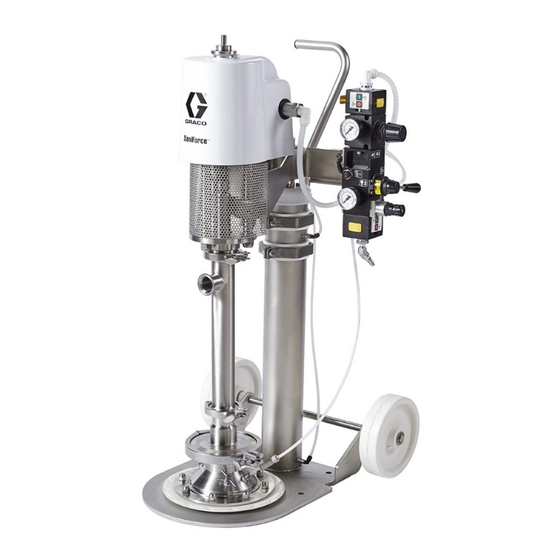
SaniForce™
SaniForce™
SaniForce™
Pail
Pail
Pail Unloader
Unloader System
Unloader
For use
use with
with food
food grade
grade bulk
For
For
use
with
food
grade
For
For professional
For
professional use
professional
use only.
use
only.
only.
Important
Important Safety
Important
Safety Instructions
Safety
Read all warnings and instructions in this manual and in manuals
identified in the Related Manuals table on page 2. Save
instructions.
instructions.
instructions.
Maximum Working Air Pressure: 100
psi (0.7 MPa, 7 bar)
Maximum Working Fluid Pressure: 650
psi (4.5 MPa, 45 bar)
System
System
bulk supply
supply of of of medium
medium to to to high
bulk
supply
medium
Instructions
Instructions
PROVEN QUALITY. LEADING TECHNOLOGY.
high viscosity
viscosity product.
product.
high
viscosity
product.
Save all all all
Save
3A5401C
EN
Advertisement

Related Manuals for Graco SaniForce SPU.A01AAA1AA0C21


Summary of Contents for Graco SaniForce SPU.A01AAA1AA0C21
- Page 1 Parts SaniForce™ SaniForce™ SaniForce™ 3A5401C Pail Pail Pail Unloader Unloader Unloader System System System For use use with with food food grade grade bulk bulk supply supply of of of medium medium to to to high high viscosity viscosity product. product.
- Page 2 Change Pump Mounting Position ....11 Related Manuals ..........2 Parts..............12 Configuration Matrix..........3 Hose Routing ............. 17 Warnings ............4 Technical Data ........... 18 Troubleshooting..........6 Graco Standard Warranty........20 Repair..............8 Pressure Relief Procedure......8 Models Models Models Model Model...
- Page 3 Configuration Matrix Configuration Matrix Matrix Configuration Configuration Matrix Check the identification plate (ID) for the following matrix to define the components of your Configuration Number of your pump. Use the system. SPU A01AAA1AA0C21 A01AAA1AA0C21 A01AAA1AA0C21 Sample Sample Sample Configuration Configuration Configuration Number: Number: Number:...
- Page 4 Warnings Warnings Warnings Warnings The following warnings are for the setup, use, grounding, maintenance, and repair of this equipment. The exclamation point symbol alerts you to a general warning and the hazard symbols refer to procedure-specific risks. When these symbols appear in the body of this manual or on warning labels, refer back to these Warnings.
- Page 5 Warnings WARNING MOVING MOVING MOVING PARTS PARTS PARTS HAZARD HAZARD HAZARD Moving parts can pinch or amputate fingers and other body parts. • Keep clear of moving parts. • Do not operate equipment with protective guards or covers removed. • Pressurized equipment can start without warning. Before checking, moving, or servicing equipment, follow the Pressure Pressure Pressure Relief...
- Page 6 Troubleshooting Troubleshooting Troubleshooting Troubleshooting • Prior to performing any repairs, perform the Pressure Relief procedure. • Check all possible problems before disassembling the ram, pump, or platen. Problem Problem Problem Cause Solution Cause Cause Solution Solution Ram will not raise or lower. Closed air valve (BA) or clogged Open, clear.
- Page 7 Troubleshooting Problem Cause Solution Problem Problem Cause Cause Solution Solution Pump operates, but output low on Restricted air line or inadequate Clear air line or increase air both strokes. air supply. supply. Insufficient air pressure; closed or Open or clean air valves, etc. clogged air valves, etc.
- Page 8 Repair Repair Repair Repair Pressure Pressure Pressure Relief Relief Relief Procedure Procedure Procedure Air Cylinder Cylinder Repair Cylinder Repair Repair Follow the Pressure Relief Procedure whenever you see this symbol. To reduce the risk of serious injury during air cylinder repairs: •...
- Page 9 Repair Apply sanitary grease to o-rings and surface of air cylinder piston rod (2) prior to assembly. Add grease to cylinder bore prior to insertion of air cylinder piston rod assembly. Engage ram top bearing alignment pin with alignment slot in air cylinder after insertion into air cylinder.
- Page 10 Repair Disassemble Disassemble Disassemble Air Air Cylinder Cylinder Cylinder Cap Seal (7) • u-cup lips face in direction of piston assembly • inner flat aligns with flat on air cylinder piston rod • ring (13) located above the seal Bearing (8) •...
- Page 11 Repair Change Pump Pump Mounting Mounting Position Position Change Change Pump Mounting Position Reassemble Reassemble Reassemble Air Air Cylinder Cylinder Cap Cylinder Cap and and Unloader Unloader Unloader 1. Align the flat side of the seal (7) and ring (13) Pump positioning is critical to ensure that all product with each other and with the space between two is removed from a pail and to ensure that undue force...
- Page 12 Parts Parts Parts Parts 3A5401C...
- Page 13 Parts Parts/Kits Quick Quick Reference Reference Parts/Kits Parts/Kits Quick Reference Use these tables as a quick reference for parts and kits. Some parts can be ordered separately in a quantity of one. Most parts are available in repair kits. Repair kits provide the total number of parts needed to perform the repair associated with the kit.
- Page 14 Parts Description Description Description Total Total Total Qty. Qty. Qty. Ref. Ref. Ref. Part Part Part Pump and and platen platen Pump Pump platen — — — 25D956 BRACKET, motor mounting 17A123 25D956 BAR, pump mount 112914 25D956 WASHER 15D008 25D956 BOLT, 3/8–16 sst —...
- Page 15 Parts Description Description Description Total Total Qty. Total Qty. Qty. Ref. Ref. Ref. Part Part Part Air control control control — — — CONTROL, air 25M879 (refer to separate air controller manual) — — — FITTING, 1/2 npt x 1/2 ptc 16F384 —...
- Page 16 Parts PTFE Platen Platen Assembly Assembly Buna - - - N N N Platen Platen Assembly Assembly PTFE PTFE Platen Assembly Buna Buna Platen Assembly 3A5401C...
- Page 17 Hose Routing Hose Routing Routing Hose Hose Routing This diagram shows how air hoses are routed and their connection points. For example, the cylinder up (CU) hose attaches at CU1 and CU2. 3A5401C...
- Page 18 Technical Data Technical Data Data Technical Technical Data Sanitary Sanitary Pail Sanitary Pail Pail Unloader Unloader Unloader Metric Metric Metric Maximum fluid working pressure 650 psi 4.5 MPa, 44.8 bar Maximum air inlet pressure 100 psi 0.7 MPa, 6.9 bar Air consumption See pump manual Maximum recommended pump...
- Page 19 Notes Notes Notes Notes 3A5401C...
- Page 20 Graco to be defective. This warranty applies only when the equipment is installed, operated and maintained in accordance with Graco’s written recommendations. This warranty does not cover, and Graco shall not be liable for general wear and tear, or any malfunction, damage or wear caused by faulty installation, misapplication, abrasion, corrosion, inadequate or improper maintenance, negligence, accident, tampering, or substitution of non-Graco component parts.
Need help?
Do you have a question about the SaniForce SPU.A01AAA1AA0C21 and is the answer not in the manual?
Questions and answers