Graco D200 Instructions Manual
Warm melt supply systems
Hide thumbs
Also See for D200:
- Repair manual (68 pages) ,
- Instructions-parts list manual (28 pages) ,
- Operation (46 pages)
Table of Contents
Advertisement
Quick Links
Instructions - Parts
Warm Melt Supply
Systems
For use with heated bulk supply of medium to high viscosity sealant and adhesive
materials. Not for use in hazardous locations. Intended for indoor use only.
D200 3 inch dual post
200 liter (55 gallon)
150 psi (1.0 MPa, 10 bar) Maximum Air Inlet Pressure
D200S 6.5 inch dual post
200 liter (55 gallon)
125 psi (0.9 MPa, 9 bar) Maximum Air Inlet Pressure
Important Safety Instructions
Read all warnings and instructions in this manual.
Save these instructions.
See page 4 for model information.
US Patent Pending
The Graco Control Architecture Electric Components
are listed in Intertek's Directory of Listed Products.
D200s (WM2179) Shown
313296A
Advertisement
Table of Contents
Troubleshooting

Related Manuals for Graco D200


Summary of Contents for Graco D200
- Page 1 For use with heated bulk supply of medium to high viscosity sealant and adhesive materials. Not for use in hazardous locations. Intended for indoor use only. D200 3 inch dual post 200 liter (55 gallon) 150 psi (1.0 MPa, 10 bar) Maximum Air Inlet Pressure D200S 6.5 inch dual post...
-
Page 2: Table Of Contents
Recirculate Function ..... 30 Graco Information ......84 Depressurize Function . -
Page 3: Related Manuals
Related Manuals Related Manuals Manuals are available at www.graco.com. Component Manuals in U.S. English: Manual Description 313529 Tandem Supply Systems Repair-Parts 313526 Supply Systems Operation 313527 Supply Systems Repair-Parts ® Check-Mate Displacement Pumps 312375 Instructions-Parts ® Check-Mate Pump Packages 312376... -
Page 4: Models
Size Style Material Material Pump Code Size Style Voltage Air Controls PTFE 200 L coated (Warm Melt 3 in. D200 no volt (55 Gal) EPDM Single Supply 2-Button 200 L System) 3 in D200i no volt Interlock (55 Gal) EPDM... -
Page 5: Warnings
Warnings Warnings The following warnings are for the setup, use, grounding, maintenance, and repair of this equipment. The exclama- tion point symbol alerts you to a general warning and the hazard symbol refers to procedure-specific risk. Refer back to these warnings. Additional, product-specific warnings may be found throughout the body of this manual where applicable. - Page 6 Warnings WARNING MOVING PARTS HAZARD Moving parts can pinch or amputate fingers and other body parts. • Keep clear of moving parts. • Do not operate equipment with protective guards or covers removed. • Pressurized equipment can start without warning. Before checking, moving, or servicing equipment, follow the Pressure Relief Procedure in this manual.
-
Page 7: Overview
Zones 1 and 2 are always used for the heated All temperatures in the warm melt supply system are platen and the heated pump respectively. controlled by Graco Control Architecture components: Fluid Control Module (FCM), Temperature Control Mod- • Zones 3 and 4 are used for the heated hose and ules (TCM), and the display module. -
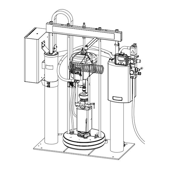
Page 8: Component Identification
Component Identification Component Identification Single Supply Systems NOTE: Do not D200s Ram Shown Lift Locations use air motor lift ring (S) to lift entire system. . 2: Single Supply System Key: Ram Assembly Platen Lift Rod Air Motor Wet Cup Heated Check-Mate Displacement Pump Main Air Line (not supplied) Heated Platen... -
Page 9: Tandem Supply Systems
Component Identification Tandem Supply Systems D200s Rams Shown Supply System A Supply System B To heated manifold (243697) r_wm2179_313269_4a . 3: Tandem Supply System Key: Ram A Ram B Heated Check-Mate Displacement Pump (Ram A and B) Heated Platen (Ram A and B) Drum Empty Sensor (partially hidden;... -
Page 10: Integrated Air Controls
Component Identification NOTE: Integrated Air Controls See F . 2 and F . 3. Before you install the system, you should be familiar with the following compo- The integrated air controls include: nents. • Main air slider valve (BA): turns air on and off to Reference numbers and letters in parentheses in the the system. -
Page 11: Air Line Accessories
See Supply Systems Operation manual. The Communications Gateway Module (CGM) provides • Air line drain valve. Not included. a control link between Graco Control Architecture based systems and a selected fieldbus. This provides the • Air line filter: removes harmful dirt and moisture means for remote monitoring and control by external from compressed air supply. -
Page 12: Fluid Control Module
Component Identification Fluid Control Module Table 2: FCM Sensor Connections Connection Sensor Description Ram A and Ram B Air motor solenoid (wire labeled 3), drum low (wire labeled 1), drum empty (wire labeled 2) Ram A Light tower Ram A + B Fluid depressurize/recirculate solenoid not used not used... -
Page 13: User Interface
Component Identification User Interface . 8: Display Module Table 3: Display Module Button Functions Button Function Powers air motor solenoid ON and OFF from Ram Operation screen (F . 68, page 79). On/Off • When ON, the air motor solenoid is ON and the active ram is pressurized. •... - Page 14 Component Identification Table 3: Display Module Button Functions Button Function Soft keys activate the mode or action represented by the icon above each button in the LCD. Soft Key See Table 4 for soft key modes and actions. Table 4: Display Soft Key Icons Icon Function Depressurize...
- Page 15 Component Identification Table 4: Display Soft Key Icons Icon Function Crossover Crossover key transitions the active ram to inactive, and inactive ram to active. Available on Warm Melt Tandem Supply Systems only. NOTE: If an alarm is present on the inactive ram, crossover will not be successful. Manual crossover is disabled in single ram operation.
- Page 16 Component Identification User Interface Display NOTE: For details regarding the user interface display see Accessories, page 72. Display Screen Components The following figure calls out the navigational, status, and general informational components of each display screen. Status Current Date and Time Navigation Mode Function Display...
-
Page 17: Installation
Installation Installation Grounding Accessories are available from Graco. Make certain all accessories are adequately sized and pressure-rated to meet the system’s requirements. Ground the supply system as instructed here and in the individual component manuals. Component Identification illustrations are only a guide for selecting and installing system components and accessories. -
Page 18: Connect Power Source
Installation Fluid supply container: follow local code. NOTE: See Power Requirements, page 7, for circuit protection requirements. Object being sprayed: follow local code. 1. Open electrical enclosure door and locate power Solvent pails used when flushing: follow local code. line filter. Use only conductive metal pails, placed on a grounded 2. -
Page 19: Adjust Drum Low/Empty Sensor
Installation Adjust Drum Low/Empty Sensor 5. Make precise adjustments by moving the sensor within the slot on the sensor bracket. 1. Position ram at desired level (low or empty). 6. Attach the sensor to the corresponding connector on the D-Sub harness of the remote DataTrak. 2. -
Page 20: Attach Drum Stops
Installation Attach Drum Stops Supply systems are shipped with drum stops in place to 1. Locate the correct set of mounting holes on the ram help position the drum on the ram. For replacement base. parts, order Kit 255477. The kit includes two each of 2. -
Page 21: Check Resistance
Installation Check Resistance Sensor Resistance Checks Check the Resistance Between the Supply System and the True Earth Ground Conduct these electrical checks with the main discon- nect OFF. NOTE: For dispense valve and hose sensor resis- The resistance between the supply system compo- tance checks, refer to your dispense valve manual nents and true earth ground must be less than 0.25 or hose manual. - Page 22 Installation Heater Resistance Checks NOTE: Check resistance at ambient room tempera- ture (63°– 77°F [17°– 25°C] Table 7: Resistance Chart of All Heaters Conduct these electrical checks with the main power Between Unit Range disconnect OFF. Zone Component Terminals Voltage (ohms) Platen 1 and 3...
-
Page 23: Hose Installation And Care
Refer to the Hotmelt/Warm Melt Heated Hose manual for details regarding hose care guidelines. Mechanical Setup 1. Fill displacement pump wet cup 2/3 full with Graco NOTE: The warm melt supply system requires Graco Throat Seal Liquid (TSL). single-circuit material hoses rated at a maximum of 1920 Watts. -
Page 24: Purge System
Purge System 3. Select a pail of material that can eliminate the fac- tory-test oil from the system. If necessary, check with Graco or the material supplier for a recom- Purging the system before the initial use can prevent mended solvent. -
Page 25: Setup
Setup Setup Flush Before Using Equipment 4. Remove the drum cover and smooth the surface of the fluid with a straightedge. The pump was tested with lightweight oil, which is left in 5. Put a full drum of fluid on the ram base, slide it back the fluid passages to protect parts. -
Page 26: System Heat Up
Setup System Heat Up Never pressurize warm melt supply system while using warm melt materials before turning on heat. Many warm melt materials tend to expand when heat- ing and may cause a heated hose to burst. Avoid the potential of bursting a hose by opening the dispense valve during system heat up and lock the dispense valve trigger open every time you shut the system down. -
Page 27: Prime
Setup Prime NOTE: To exit Prime Mode before the timer expires, press the Pump Prime key . The display prompts the operator to confirm. See F . 20. Select to exit prime. 1. Make sure the system is at required temperature. 2. -
Page 28: Operation
Operation Operation Pressure Relief Procedure 9. Open all fluid drain valves on ram(s). Have a con- tainer ready to catch the drainage. Leave fluid drain valves open until ready to dispense again. If you suspect that the dispense tip/nozzle or hose is completely clogged, or that pressure has not been fully relieved after following the steps above, very slowly This procedure describes how to relieve pressure for the... -
Page 29: Start And Adjust Pump
Operation 5. Put a full drum of fluid on the ram base, slide it back 4. When new screen appears with prompt, select against the drum stops, and center it under the platen (D). An optional drum roller kit is available to to start pump. -
Page 30: Recirculate Function
Operation In Ram Operation screen, press the Crossover key Recirculate Function . The display prompts the operator to confirm. Use Recirculate Mode to pump fluid from the drum, through the pump, and back into the drum on the cur- rently active ram. See F . -
Page 31: Depressurize Function
Operation Depressurize Function Change Drums Follow the Pressure Relief Procedure on page 28. Shutting off power or removing power from the system NOTE: Follow this procedure to change the drum on will not depressurize the system. a fully heated warm melt supply system. Use the Depressurize function to relieve fluid pressure from the pump outlet to below the platen on the currently NOTE: Follow this procedure for either ram if using... -
Page 32: Shutdown
Operation 3. Once the platen clears the drum, release the blowoff Shutdown air button (BG) and allow the ram to rise to its full height. 2-Button Interlock: If system has this fea- Follow the procedure below for normal system shut ture, the ram will stop as it nears the top. -
Page 33: Maintenance
Maintenance Maintenance Platen Maintenance If the platen does not come out of the pail easily when the pump is being raised, the air assist tube or check valve may be plugged. A plugged valve prevents air from reaching the underside of the plate to assist in raising it from the pail. -
Page 34: Electrical Enclosure
Maintenance 5. Remove excess fluid. Use a soft wire brush on 3. Check for damaged or loose wires. Check connec- heater coils (48). tions from cable track. 6. Inspect platen heater blocks (43) for burn or melt Check GFCI Circuit Breaker spots. -
Page 35: Pump Heaters
Maintenance Pump Heaters 5. Check for damaged wires and connections. 6. Ensure heaters (44) are secure so they cannot 1. Turn the main disconnect on the electrical control rotate on pump. panel door to the OFF position to disconnect power. 2. -
Page 36: Alarms
Alarms Alarms Diagnose Alarms Warm Melt alarms alert you to a problem and help pre- vent system shutdown or application errors. If an alarm occurs, operation may stop and the following occurs. See Alarm Codes and Troubleshooting, page 36, for causes and solutions to each alarm code. - Page 37 Alarms Alarm Code Alarm Problem Cause Solution Clear Alarm Fluid Control Module (continued) DA1X Pump Runaway A Pump is running faster than Correct runaway condition Cleared from Ram Alarm set runaway limit due to: and clear alarm on Status screen. See Appendix A, DA2X Pump Runaway B screen 1.
- Page 38 Alarms Alarm Code Alarm Problem Cause Solution Clear Alarm Fluid Control Module (continued) DD1X A - Pump Diving Pump leak. Worn valve or packings. Cleared from Ram Alarm See Check-Mate Displace- screen. See Appendix A, DD2X B - Pump Diving ment Pump manual.
- Page 39 Alarms Alarm Code Alarm Problem Cause Solution Clear Alarm Temperature Control Modules (continued) T6AX No Temp Rise Tripped circuit breaker. Visually check circuit Cleared from Heat Run breaker for a tripped condi- screen. See Appendix A, tion. page 73. Low power. Measure voltage across terminals 2 and 4.
- Page 40 Alarms Alarm Code Alarm Problem Cause Solution Clear Alarm Temperature Control Modules (continued) A1AX Undercurrent Tripped circuit breaker. Visually check circuit Cleared from Heat Run breaker for a tripped condi- screen. See Appendix A, tion. page 73. Low power. Measure voltage across terminals 2 and 4.
- Page 41 Alarms Alarm Code Alarm Problem Cause Solution Clear Alarm Temperature Control Modules (continued) V4MX High DC Voltage Faulty DC power supply. Measure that DC supply Cleared from Heat Run output is 24V. If not, replace screen. See Appendix A, supply. page 73.
-
Page 42: Troubleshooting
Troubleshooting Troubleshooting NOTE: Troubleshooting covered in this manual is 1. Follow Pressure Relief Procedure, page 28, specific to warm melt heat functions. Refer to Sup- before disassembling any part of the warm melt ply Systems Repair-Parts manual and/or Tandem supply system. Supply Systems Repair-Parts manual for ram trou- 2. - Page 43 Troubleshooting Problem Cause Verification Solution No heat. Tripped circuit breaker. Visually check circuit Determine cause of tripped breaker for a tripped condi- circuit breaker. Then repair tion. fault and reset main circuit breaker. Low power. Measure voltage across 1. If voltage is lower than terminals 2T1 and 4T2 on expected, use electrical main disconnect.
- Page 44 Troubleshooting Problem Cause Verification Solution No heat (continued). Contactor not closing. Turn on heat for zone A1 or 1. Verify cable 15W902 B1and ensure contactor from the high power closes. TCM is connected cor- rectly. 2. Verify that there are no other error conditions that would prevent heater from starting.
- Page 45 Troubleshooting Problem Cause Verification Solution Heating is slow. Heater defective. Measure resistance of Follow Heater Resistance heater. Checks, page 22. Low power. Measure voltage across 1. If voltage is lower than terminals 2T1 and 4T2 on expected, use electrical main disconnect. Voltage schematic to locate should measure between faulty wiring or connec-...
-
Page 46: Repair
Tighten nut (HA) above crossbar to lock motor 4. Disconnect air motor: in place. a. For 55 gallon platen (D200 3 in. and D200s 6.5 in. supply systems): Loosen nut (HB) below crossbar. Use wrench to hold lift ring adapter (HD) in place and loosen threaded rod (HC) above crossbar with another wrench. -
Page 47: Displacement Pump
If the air motor does not require servicing, leave it attached to its mounting. If the air motor does need to be removed, see Remove Air Motor, page 46. D200 and D200s Supply Systems 1. Disconnect air hose and ground wire from air motor. TI10648A . -
Page 48: Disconnect Pump From Platen
Repair Install Displacement Pump 3. Remove four screws (103a) and four clamps (103b). D200 and D200s Supply Systems 103a 1. Insert displacement pump on platen. See Connect Pump to Platen, page 48. 103b 2. Lower air motor. Use wrench on nut (EA) to lower air motor. -
Page 49: Replace Pump Heaters
Repair Replace Pump Heaters 5. Install new pump heater bands and secure with screws. NOTE: To ease pump heater band installation, first install heater bands on middle of displacement pump. Then slide heater band up or down into cor- rect location. 1. -
Page 50: Replace Platen Wipers
Repair 3. Remove platen heater blocks (43). Replace Ram Piston Rod Seals a. Use a hex wrench to remove three nuts (59) and washers (11, 64) from each heater block. b. Remove screws (12) from junction box cover (96). Loosen strain relief nut (91), and remove 1. -
Page 51: Electrical Enclosure
Repair Electrical Enclosure Prior to repairing any component of the electrical enclo- sure (7), turn the main disconnect on the electrical con- Outbound trol panel door to the OFF position to disconnect power. Power Outbound Power is still connected to the power line filter (359) Power even after the power is disconnected to the electrical enclosure. - Page 52 Repair Replace High Power Temperature Control Upgrade Temperature Control Module Module Software 1. Open enclosure door (302). Disconnect outbound 1. Open enclosure door (302). Remove access cover power supply and RTD cables from high power TCM from module(s). (311). See F .
- Page 53 Repair Replace Circuit Breakers 4. Remove screws (12) and washers (11) from bottom bracket (39) and side bracket (50) of enclosure. 1. Open enclosure door (302). Disconnect wires from circuit breaker (317, 319). 11, 12 2. Push in circuit breaker tab and pull out breaker. .
-
Page 54: Display/User Interface
Repair Display/User Interface Replace Display NOTE: Order Kit 257165 for replacement. Upgrade Software NOTICE To avoid damaging circuit board, wear a grounding NOTICE strap. To avoid damaging circuit board, wear a grounding strap. 1. Disconnect power. 1. Disconnect power. 2. Pull display (20) out of bracket (22) clips to remove 2. -
Page 55: Replace Fluid Control Module
Repair Replace Fluid Control Module 5. Loosen both screws from FCM and pull FCM off base (33). 1. Disconnect power to system. 2. Remove front shroud (16) and back shroud (17). Screws . 51: Remove FCM 6. Replace with new FCM, and secure with screws. 7. -
Page 56: Replace Cable Track
Repair Upgrade FCM Software Replace Cable Track 1. Disconnect power to system. 2. Remove front shroud (16) and back shroud (17). 3. Remove access cover (41) from FCM (36). NOTE: Order Kit 257163 for replacement. 4. Insert and press token firmly into slot. 1. - Page 57 Repair 4. Remove screws (12) from junction box cover (96). 8. Lift out cable track assembly and cables. 5. Loosen strain relief nut (91), and remove junction 9. Replace with new cable track kit. Secure new cable box cover. track to junction box using mounting screws. 6.
-
Page 58: Electrical Schematics
Electrical Schematics Electrical Schematics Ram A Schematic 313296A... -
Page 59: Ram B Schematic
Electrical Schematics Ram B Schematic 313296A... -
Page 60: Displacement Pump And Platen Schematics
Electrical Schematics Displacement Pump and Platen Schematics 313296A... -
Page 61: Junction Box Schematic
Electrical Schematics Junction Box Schematic 313296A... -
Page 62: Cable Track Schematic
Electrical Schematics Cable Track Schematic 313296A... -
Page 63: Electrical Enclosure Schematic
Electrical Schematics Electrical Enclosure Schematic 313296A... -
Page 64: Parts
RAM ASSEMBLY, D200si, 6.5 in. 1 or 2 page 65) RAM ASSEMBLY, D200, 3 in. 1 or 2 24C489 For D200 and D200i Ram A RAM ASSEMBLY, D200i, 3 in. 1 or 2 24C491 For D200s and D200si Ram A see Table PUMP, Check-Mate;... -
Page 65: Warm Melt Kits For D200 Systems
Kit 257316 with Display for D200 and D200i Systems Kit 257317 with Display for D200s and D200si Systems Kit 24C489 with Display for Ram A of Tandem D200 and D200i Systems Kit 24C490 without Display for Ram B of Tandem D200 and D200i Systems... - Page 66 Parts 72, 73 83, 84, 85 61, 62 11, 12 11, 26, 58, 59 54, 55 r_wm_2179_313296_12a 313296A...
- Page 67 Parts 45, 79 68, 69, 97, 98 67, 99 103a 103b 103c Torque to 12 ft-lbs (16.2 N•m) 46, 56, 82 57, 97, 100, 102 313296A...
- Page 68 Parts 68, 97, 99 r_wm_2179_313296_11a D200 Warm Melt Kits Ref. Part Description Qty. 121070 SCREW, machine; #8-32 x 1 Ref. Part Description Qty. 100016 WASHER, lock 31★ CABLE, CAN, female/female; 101682 SCREW, cap, sch 0.5 m 13❖ SCREW, cap, hex hd; 7/16-14...
- Page 69 Parts Ref. Part Description Qty. Ref. Part Description Qty. BRACKET, mounting, top WIRE, ground †❋15W959 255392 KIT, mounting, displacement ◆✠15W705 pump 51✛ 15W706 ENCLOSURE, pump, front 130a 102637 SCREW, cap 52✛ 15W707 ENCLOSURE, pump, rear 103b 276025 CLAMP CONDUIT; 12.9 mm 103c 109495 O-RING COUPLER, conduit...
-
Page 70: Electrical Enclosures Parts
Parts Electrical Enclosures Parts 257158 for single supply systems and ram A of tandem supply systems 257291 for ram B of tandem supply systems Side View 257158 Shown 343, 358 333, 334, 335 315, 326 302, 303, 304, 305 325, 353 320, 354 308, 309, 310 315, 326... - Page 71 Parts Electrical Enclosure Parts Ref. Part Description Qty. 186620 LABEL, ground Ref. Part Description Qty. 112905 WASHER, plain ENCLOSURE 123373 FILTER, power line; single phase DOOR, enclosure 123374 SUPPLY, power; 24Vdc, 2.5A, 60W 101682 SCREW, cap, sch (included in only 257158) 100016 WASHER, lock COVER, buss bar, single 100015 NUT, hex, mscr...
-
Page 72: Accessories
Accessories Accessories Platen Cover, 255691 Two platen covers. See manual 406681 for more infor- mation. Two-Zone Expansion Kit, 24C223 For adding two zones of heat to a Warm Melt Supply System. The two extra zones are controlled through the Warm Melt display. Two-Zone Accessory Kit, 24C222 Controls two zones of heat;... -
Page 73: Display Module Details
Appendix A Appendix A Display Module Details Status The current system status is displayed on the right of the menu bar. If there is an error, an event icon and either a Power Up Screen text description of the event or the standard error code The following screen appears when the display module for the event is displayed. -
Page 74: Setup Mode
Appendix A Setup Mode System Setup This screen enables users to change system setup Setup mode enables users to set system parameters. parameters. Password Screen In Run Mode, press the Setup key . If the password is not set to 0000, the Password screen will appear. Enter the password to continue in Setup Mode. - Page 75 Appendix A Heater System Setup Screen Maintenance Setup Screen 1 This screen enables users to set the parameters for This screen enables users to change system and platen seal maintenance intervals. each heater zone. . 60: Heater System Setup Screen .
- Page 76 Appendix A Hardware Setup Screen 1 Hardware Setup Screen 2 This screen enables users to specify if a fluid filter moni- This screen enables users to specify if a fluid solenoid is tor is installed, and set the high and low limits for the installed, and if a drum low sensor is installed.
- Page 77 Appendix A Advanced Setup Screen 1 Advanced Setup Screen 2 This screen enables users to set units that display on This screen enables users to set the pump size (in other screens. cc/cycle) and the drum fill volume (in volume units). The drum fill volume is the amount of material in a new drum, which is used to calculate the volume of material remaining during operation.
- Page 78 Appendix A Advanced Setup Screen 3 Advanced Setup Screens 4 and 5 This screen enables users to set the date, time, and These screens contain software part number and ver- date format. sion information for system components. . 66: Advanced Setup Screen 3 .
-
Page 79: Run Mode
Appendix A Run Mode Heat Run Screen The Heat Run screen displays information for the four The Run screens display information related to system heater zones. See F . 69 for information about each operation. zone. The icon on the upper right is present if the zone is enabled, otherwise the space is blank. - Page 80 Appendix A Status Screens Status Screen 2 NOTE: Status screen 2 is only available if the filter NOTE: Press to navigate among the option is enabled. See Hardware Setup Screen 2, page 76. Status screens. This screen displays the fluid filter inlet pressure, outlet Status Screen 1 pressure, and the pressure drop across the filter.
- Page 81 Appendix A Maintenance Screen Alarm Screens The maintenance screens enable users to establish a The alarm screens display the type of alarm currently preventive maintenance schedule based on the system occurring on each ram. application and repair history. This screen displays the number of maintenance units remaining before preven- tive maintenance is due for the platen seals and pump.
-
Page 82: Dimensions
D200s Shown (ram down) (ram up) Model in. (mm) in. (mm) in. (mm) in. (mm) in. (mm) in. (mm) in. (mm) D200 102.3 (2599) 72.6 (1844) 21.0 (533) 25.0 (635) 38.0 (965) 42.0 (1067) 56.4 (1433) D200s 104.9 (2665) 74.3 (1887) 23.0 (584) -
Page 83: Technical Data
Technical Data Max air input pressure (supply system) D200 - 3 in. dual post, 55 gal. (200 L) ... . 150 psi (1.0 MPa, 10 bar) D200s - 6.5 in. dual post, 55 gal. (200 L).. -
Page 84: Graco Standard Warranty
With the exception of any special, extended, or limited warranty published by Graco, Graco will, for a period of twelve months from the date of sale, repair or replace any part of the equipment determined by Graco to be defective.
Need help?
Do you have a question about the D200 and is the answer not in the manual?
Questions and answers