
Related Manuals for CYP CSC-6030CVE


Summary of Contents for CYP CSC-6030CVE
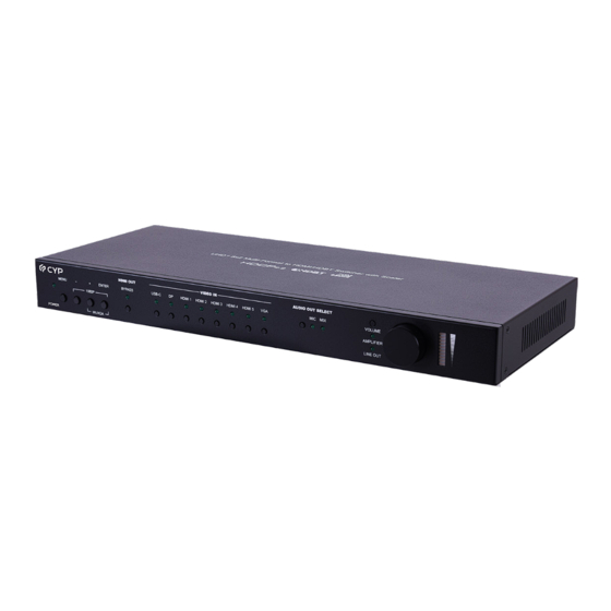
- Page 1 CSC-6030CVE 8x2 Multi-Format to HDMI/HDBaseT Switcher with Scaler Operation Manual Operation Manual...
- Page 3 DISCLAIMERS The information in this manual has been carefully checked and is believed to be accurate. Cypress Technology assumes no responsibility for any infringements of patents or other rights of third parties which may result from its use. Cypress Technology assumes no responsibility for any inaccuracies that may be contained in this document.
- Page 4 SAFETY PRECAUTIONS Please read all instructions before attempting to unpack, install or operate this equipment and before connecting the power supply. Please keep the following in mind as you unpack and install this equipment: • Always follow basic safety precautions to reduce the risk of fi re, electrical shock and injury to persons.
-
Page 5: Table Of Contents
CONTENTS 1. Introduction ............1 2. Applications ............. 1 3. Package Contents ........... 2 4. System Requirements ........2 5. Features............3 6. Operation Controls and Functions ....4 6.1 Front Panel ..........4 6.2 Rear Panel........... 5 6.3 IR Cable Pinouts.......... 8 6.4 RS-232 Pinout and Defaults ...... -
Page 6: Introduction
1. INTRODUCTION This 8 by 2 multi-format scaling switcher provides HDMI, USB-C, DisplayPort, and VGA inputs which can be freely selected for output at a scaled resolution of the user’s choosing over the mirrored HDMI and HDBaseT outputs. The HDMI, DisplayPort, and USB-C inputs and HDMI output support resolutions up to 4K@60 (4:4:4, 8-bit) while the VGA input supports resolutions up to WUXGA. -
Page 7: Package Contents
3. PACKAGE CONTENTS • 1× UHD 8x2 Multi-Format to HDMI/HDBaseT Switcher with Scaler • 1× 24V/6.25A DC Power Adapter • 1× Rackmount Ears (Set of 2) • 1× Shockproof Feet (Set of 4) • 1× Operation Manual 4. SYSTEM REQUIREMENTS •... -
Page 8: Features
5. FEATURES • HDMI 2.0 and DVI 1.0 compliant • HDCP 1.x and 2.2 compliant • 8 video inputs (1×USB-C, 1×DisplayPort, 5×HDMI, 1×VGA) • 2 mirrored video outputs (1×HDMI, 1×HDBaseT) • Supports switching and scaling of all AV inputs for display over the mirrored HDMI and HDBaseT outputs •... -
Page 9: Operation Controls And Functions
6. OPERATION CONTROLS AND FUNCTIONS 6.1 Front Panel POWER HDMI OUT HDMI OUT VIDEO IN AUDIO OUT SELECT AUDIO OUT SELECT VIDEO IN MENU MENU ENTER ENTER BYPASS BYPASS USB-C USB-C HDMI 1 HDMI 1 HDMI 2 HDMI 2 HDMI 3 HDMI 3 HDMI 4 HDMI 4... -
Page 10: Rear Panel
VOL. Rotary Knob & LEDs: Rotating the knob increases or decreases the currently selected audio output’s volume level. The LED bar will change according to the current level. Pressing in on the knob toggles the audio mute function. 6.2 Rear Panel MIC IN ANALOG AUDIO AUDIO OUT... - Page 11 IR OUT Port: Connect to an IR Blaster to transmit IR signals from the other end of the HDBaseT connection to devices within direct line-of- sight of the IR Blaster. Note: IR can only be routed across a single HDBaseT connection at a time.
- Page 12 LAN Port: Connect directly, or through a network switch, to your PC/ laptop to control the unit via Telnet/WebGUI and to extend the network across the HDBaseT connection. DC24V 4-pin DIN Port: Plug the 24V DC power adapter into this port and connect it to an AC wall outlet for power.
-
Page 13: Ir Cable Pinouts
6.3 IR Cable Pinouts IR Extender IR Blaster Cable Cable Power Infrared Infrared Power Not Used Ground 6.4 RS-232 Pinout and Defaults Serial Port Default Settings Baud Rate 19200 Data Bits Parity Bits None Stop Bits Flow Control None RS-232 Port 1 (Unit control) RS-232 Port 2 (HDBaseT extension) 4-pin Terminal Block 4-pin Terminal Block... -
Page 14: Osd Menu
6.5 OSD Menu All functions of this unit can be controlled by using the OSD (On Screen Display) which is activated by pressing the MENU button on the front of the unit. Use the + (PLUS), − (MINUS), and ENTER buttons to navigate the OSD menu. - Page 15 VIDEO 2ND LEVEL 3RD LEVEL 4TH LEVEL NATIVE HDMI Output Resolution Native HDBT 640x480@60 800x600@60 1024x768@60 1280x768@60 1360x768@60 1280x720@60 1280x800@60 1280x1024@60 1440x900@60 1400x1050@60 1680x1050@60 1600x1200@60 1920x1080@60 1920x1200@60RB 2560x1600@60RB 720x480p 720x576p 1280x720p50 1280x720p60 1920x1080p24 1920x1080p25 1920x1080p30 1920x1080p50 1920x1080p60 3840x2160p24 3840x2160p25...
- Page 16 VIDEO 2ND LEVEL 3RD LEVEL 4TH LEVEL 3840x2160p30 3840x2160p50 3840x2160p60 3840x2160p50(420) 3840x2160p60(420) 4096x2160p24 4096x2160p25 4096x2160p30 4096x2160p50 4096x2160p60 4096x2160p50(420) 4096x2160p60(420) Aspect BEST FIT Pan Scan Letterbox Under 1 Under 2 Follow In Overscan Full BLACK No Signal Color White Blue Green Blank...
- Page 17 VIDEO 2ND LEVEL 3RD LEVEL 4TH LEVEL Freeze Auto Setting Auto Sync Off Auto Route Auto Switch HDCP Setting HDCP On USB-C Refer to Source REFER TO DISPLAY Support Off HDCP On DP Refer to Source REFER TO DISPLAY Support Off HDCP On HDMI 1 Refer to Source REFER TO DISPLAY...
- Page 18 1) HDMI Out Bypass: Enable or disable the video output bypass mode. When bypass is enabled, HDR video and bitstream audio can be supported, however it will disable the unit’s scaling and video adjustment functions. Note: This setting aff ects both the HDMI and HDBaseT outputs. This setting does not enable audio bypass.
- Page 19 PICTURE 2ND LEVEL 3RD LEVEL 4TH LEVEL 0~1023 (512) Color Gain R Color Gain G 0~1023 (512) 0~1023 (512) Color Gain B Color Off set R 0~1023 (512) Color Off set G 0~1023 (512) Color Off set B 0~1023 (512) Brightness 0~60 (30) 0~60 (30)
- Page 20 3) Brightness/Contrast: Set the overall brightness and contrast of the scaled output image. 4) Fine Tune HDMI (Digital sources only): Hue: Set the hue shift of the scaled output image. Saturation: Set the color saturation level of the scaled output image. ...
- Page 21 AUDIO 2ND LEVEL 3RD LEVEL 4TH LEVEL HDMI Out Bypass Audio Routing Follow User FOLLOW VIDEO Fixed Analog 1 Fixed Analog 2 Fixed Analog 3 Fixed Analog 4 Fixed Analog 5 Fixed Analog 6 EMBEDDED Follow User Setting Audio On USB-C Analog 1 Analog 2 Analog 3...
- Page 22 AUDIO 2ND LEVEL 3RD LEVEL 4TH LEVEL Follow User Setting Audio On VGA ANALOG 1 Analog 2 Analog 3 Analog 4 Analog 5 Analog 6 MIXER OFF Output Mixer Mixer On Mic Only Mic Gain 0~100 (0) 0~100 (85) HDMI/HDBT Out Volume Analog Out Volume 0~100 (85) Speaker Out Volume...
- Page 23 “Follow User Setting” section. Follow Video: All digital sources will use their native embedded audio content. The VGA source will use the Analog 1 audio input. Fixed Analog 1~6: Forces all video sources to be paired with the selected analog audio source.
- Page 24 2ND LEVEL 3RD LEVEL OSD Menu Timeout INFO Display Off 1) H/V Position: Controls the position of the OSD menu. 2) Transparency: Set the transparency level of the OSD menu’s background. The available range is from Level 0 (fully opaque) to Level 8 (fully transparent).
- Page 25 ETHERNET 2ND LEVEL 3RD LEVEL 4TH LEVEL STATIC IP Mode DHCP 0~255 (192) Static IP Setting Static IP 0~255 (168) 0~255 (1) 0~255 (50) Mask 0~255 (255) 0~255 (255) 0~255 (0) 0~255 (0) Gate 0~255 (192) 0~255 (168) 0~255 (1) 0~255 (254) [Current IP address] [Unit’s MAC address]...
- Page 26 EDID 2ND LEVEL 3RD LEVEL DEFAULT FHD 2CH EDID On USB-C Default FHD MCh Default UHD 2Ch Default UHD MCh Default UHD+ 2Ch Default UHD+ MCh Default VGA User 1 User 2 Sink HDMI Sink HDBT EDID On DP [Same options as for USB-C] EDID On HDMI 1 [Same options as for USB-C] EDID On HDMI 2...
- Page 27 1) EDID Selection: Select the EDID to use with each input. Note: In most cases, assigning a new EDID to an input will cause the aff ected input to briefl y blink out while the source adapts to the new information.
- Page 28 FACTORY 2ND LEVEL 3RD LEVEL Reset All Execute FW Update From USB Execute 1) Reset All: Selecting “Execute” will reset all of the unit’s settings back to their factory defaults. 2) FW Update From USB: Provides a way to update the unit’s fi rmware. Insert a USB thumb drive, with a valid fi...
-
Page 29: Webgui Control
6.6 WebGUI Control • Device Discovery Please obtain the “Device Discovery” software from your authorized dealer and save it in a directory where you can easily fi nd it. Connect the unit and your PC/Laptop to the same active network and execute the “Device Discovery”... - Page 30 • WebGUI Overview After connecting to the WebGUI’s address in a web browser, the login screen will appear. Please enter the appropriate user name and password then click “Submit” to log in. Note: The default user name and password is “admin”. On the left side of the browser you will see the following menu tabs where all primary functions of the unit are controllable via the built in WebGUI.
-
Page 31: Video Tab
6.6.1 Video Tab This page provides video routing settings, I/O renaming options and control over the video output signal’s format and behavior. To begin assigning a new video route, please click an output button and then click on the button of the preferred input port. As you select each button they will change their color to orange. - Page 32 can be supported, however it will disable the unit’s scaling and video adjustment functions. Note: This setting aff ects both the HDMI and HDBaseT outputs. This setting does not enable audio bypass. Output Resolution: Selects the output resolution to use when HDMI bypass is disabled.
-
Page 33: Hdcp Tab
have been executed on the unit. Setting this to “OFF” forces the unit to always output sync. Output Auto Route: Enable or disable automatically switching to any newly detected source. 6.6.2 HDCP Tab Provides control over the HDCP behavior of each input. To confi gure the HDCP support on one or more inputs, select the preferred inputs on the left, and then select the HDCP mode on the right. -
Page 34: Picture Tab
6.6.3 Picture Tab This tab provides controls over the scaled video output’s color, brightness, contrast. When a digital source is selected hue, saturation, sharpness and noise reduction are also controllable. When a VGA input is selected, the available controls will change and auto set, H/V position, clock and phase will become adjustable instead. - Page 35 Sharpness: Provides control over the amount of sharpness processing to apply to the scaled output image. Noise Reduction: Provides control over the aggressiveness of the digital noise reduction processing when applied to the scaled output image. Selecting “Off ” disables all noise reduction processing. 3) Picture Settings (VGA Source): ...
-
Page 36: Audio Tab
6.6.4 Audio Tab This tab provides control over how audio is routed within the unit as well as control over audio mixing, individual output volume and the microphone’s gain level. 1) Audio Settings: HDMI Volume & Mute: Set the volume level, or mute the audio, for the HDMI and HDBaseT audio outputs. - Page 37 Output Mixer: Set the microphone mixing mode of the unit. - Mixer Off : Disable the audio mixer. - Mixer On: Enable the audio mixer. Audio from the current source and the microphone will be mixed together. - MIC Only: Output only the microphone audio source. This mode will override all other audio selections.
-
Page 38: Osd Tab
6.6.5 OSD Tab This tab provides controls over the appearance of the unit’s informational OSD and OSD menu. 1) H/V Position: Controls the position of the OSD menu. 2) Transparency: Controls the transparency level of the OSD menu’s background. The available range is from Level 0 (fully opaque) to Level 8 (fully transparent). -
Page 39: Edid Tab
6.6.6 EDID Tab This tab provides control over the EDID settings of all inputs. This unit provides the option of seven standard EDIDs, two sink sourced EDIDs and two user uploaded EDIDs that can be assigned to each input port individually. The names of the two user uploaded EDIDs can changed if desired. - Page 40 fi le has been selected, please click the “Upload” button in the window, and the fi le will be transferred to the unit. 2) Sink EDID Download: To save the EDID from one of the connected displays to your local PC, select the appropriate sink from the dropdown list then press the “Download”...
-
Page 41: System Tab
6.6.7 SYSTEM TAB Click on the “System” tab to make changes to various system settings. From this tab you can change the WebGUI login username and password as well as confi gure the relay settings. Finally, this tab provides buttons to reset the unit to factory defaults and to update the fi... - Page 42 4) Trigger In 1~8: Use each dropdown to set the input to be selected, if any, when each trigger is activated. 5) Reset to Default: Press the “Factory Default” button to reset the unit to its factory default state. After the reset is complete, the unit will reboot automatically.
-
Page 43: Telnet Control
6.7 Telnet Control Before attempting to use Telnet control, please ensure that both the unit and the PC are connected to the same active networks. Start your preferred Telnet/Console client, or use the built in client provided by most modern computer operating systems. After starting the client, connect by using the current IP address of the unit and port 23 (if the communication port number used by the unit has not been changed previously). - Page 44 COMMAND Description and Parameters get model name Show the unit’s model name get model type Show the index number of the unit’s product type. set factory default Reset the unit to the factory defaults. set system reboot Reboot the unit. set ip mode static...
- Page 45 COMMAND Description and Parameters set static netmask N1 Set the unit’s static netmask. N1 = X.X.X.X [X = 0 ~ 255, Netmask] get static netmask Show the unit’s current static netmask. set static gateway N1 Set the unit’s static gateway address. N1 = X.X.X.X [X = 0 ~ 255, Gateway address] get static gateway...
- Page 46 COMMAND Description and Parameters set out A route N1 Route the specifi ed input to both outputs. Available values for N1: [USB-C input] [DisplayPort input] [HDMI input 1] [HDMI input 2] [HDMI input 3] [HDMI input 4] [HDMI input 5] [VGA input] get out A route...
- Page 47 COMMAND Description and Parameters get in N1 timing string Show the index number and description of the current resolution detected on the specifi ed input. Available values for N1: [USB-C input] [DisplayPort input] [HDMI input 1] [HDMI input 2] [HDMI input 3] [HDMI input 4] [HDMI input 5] [VGA input]...
- Page 48 COMMAND Description and Parameters [800x600@60] [1024x768@60] [1280x768@60] [1360x768@60] [1280x720@60] [1280x800@60] [1280x1024@60] [1440x900@60] [1400x1050@60] [1680x1050@60] [1600x1200@60] [1920x1080@60] [1920x1200@60RB] [2560x1600@60RB] [720x480p] [720x576p] [1280x720p50] [1280x720p60] [1920x1080p24] [1920x1080p25] [1920x1080p30] [1920x1080p50] [1920x1080p60] [3840x2160p24] [3840x2160p25] [3840x2160p30] [3840x2160p50] [3840x2160p60] [3840x2160p50(4:2:0)] [3840x2160p60(4:2:0)] [4096x2160p24] [4096x2160p25] [4096x2160p30] [4096x2160p50] [4096x2160p60] [4096x2160p50(4:2:0)] [4096x2160p60(4:2:0)] get out A timing...
- Page 49 COMMAND Description and Parameters get out A timing string Show the description string of the current resolution used by both outputs. get in source list List the port type of all inputs on the unit. get out timing list List all available output resolutions with their local index numbers. set out A contrast N1...
- Page 50 COMMAND Description and Parameters set out A sharpness N1 Set the scaled output’s sharpness level. N1 = 0~63 [Sharpness level] get out A sharpness Show the sharpness level when the output is scaled. set out A nr N1 Set the amount of noise reduction to apply when the output is scaled. Available values for N1: [Off...
- Page 51 COMMAND Description and Parameters set out A auto sync off N1 Enable or disable the Auto Sync Off function and set the timeout length. Available values for N1: [Disabled] [30 seconds] [60 seconds] get out A auto sync off Show the current Auto Sync Off...
- Page 52 COMMAND Description and Parameters set out A g off set N1 Set the scaled output’s green off set. N1 = 0~1023 [Green off set] get out A g off set Show the scaled output’s current green off set. set out A b off set N1 Set the scaled output’s blue off...
- Page 53 COMMAND Description and Parameters set in 8 vposition N1 Set the PC vertical position for the VGA input. N1 = 0~250 [Horizontal position] get in 8 vposition Show the current PC vertical position for the VGA input. set out A video mode N1 Enable or disable the video output bypass mode.
- Page 54 COMMAND Description and Parameters get out A freeze Show the current video output freeze state. set out A osd timer N1 Set the OSD menu’s timeout value. Available values for N1: [Timeout disabled] [5 seconds] [10 seconds] [15 seconds] [20 seconds] [25 seconds] [30 seconds] [35 seconds]...
- Page 55 COMMAND Description and Parameters set out A osd transparency level N1 Set the transparency level of the OSD menu. N1 = 1~8 [Transparency level] get out A osd transparency level Show the current transparency level of the OSD menu. set out A osd info display N1 Enable/disable the info OSD, or set it to display briefl...
- Page 56 COMMAND Description and Parameters set audio out N1 mute N2 Enable or disable muting the specifi ed audio output. Available values for N1: [HDMI audio output] [HDBaseT audio output] [Standard analog audio output] [Amplifi ed analog audio output] Available values for N2: [Mute disabled] [Mute enabled] Note: The HDMI and HDBaseT outputs share their settings.
- Page 57 COMMAND Description and Parameters get audio out A route Show the unit’s current audio source selection behavior. set audio out N1 volume N2 Set the volume level of the specifi ed output’s audio. Available values for N1: [HDMI audio output] [HDBaseT audio output] [Standard analog audio output] [Amplifi...
- Page 58 COMMAND Description and Parameters set audio out A mode N1 Enable or disable the HDMI/HDBaseT audio output bypass mode. Available values for N1: [Audio bypass disabled] [Audio bypass enabled] get audio out A mode Show the current HDMI/HDBaseT audio output bypass mode state. set audio out N1 delay N2...
- Page 59 COMMAND Description and Parameters set video in N1 audio route N2 Set the audio source to use with the specifi ed video input when Follow User Mode is enabled. Available values for N1: [USB-C input] [DisplayPort input] [HDMI input 1] [HDMI input 2] [HDMI input 3] [HDMI input 4]...
- Page 60 COMMAND Description and Parameters get audio mixer in 1 volume Show the current microphone input mixer gain level. set in N1 edid N2 Set the EDID to use on the specifi ed input. Available values for N1: [USB-C input] [DisplayPort input] [HDMI input 1] [HDMI input 2] [HDMI input 3]...
- Page 61 COMMAND Description and Parameters get in edid list List all available EDID selections. set in N1 hdcp mode N2 Set the HDCP behavior of the specifi ed input. Available values for N1: [USB-C input] [DisplayPort input] [HDMI input 1] [HDMI input 2] [HDMI input 3] [HDMI input 4] [HDMI input 5]...
- Page 62 COMMAND Description and Parameters get in N1 hdcp status Show the current HDCP status of the specifi ed input. Available values for N1: [USB-C input] [DisplayPort input] [HDMI input 1] [HDMI input 2] [HDMI input 3] [HDMI input 4] [HDMI input 5] Possible response values: [No HDCP] [HDCP 1.x]...
- Page 63 COMMAND Description and Parameters get relay N1 Show the current state of the specifi ed relay. N1 = 1~2 [Relay port number] Note: Commands will not be executed unless followed by a carriage return. Commands are not case-sensitive.
-
Page 64: Connection Diagram
7. CONNECTION DIAGRAM Display Display Source Source Screen Volume Screen Volume Down Down 1.5m CD Player Powered 60° 60° Speakers Microphone IR Input Input IR Output Router RS-232 Power Supply MIC IN ANALOG AUDIO AUDIO OUT RELAY L+ L- R+ R- INPUT RS-232 L- G R+ R-... -
Page 65: Specifications
8. SPECIFICATIONS 8.1 Technical Specifi cations HDMI Bandwidth 18Gbps DisplayPort Bandwidth 21.6Gbps USB-C Bandwidth 21.6Gbps VGA Bandwidth 165MHz HDBaseT Bandwidth 10.2Gbps Input Ports 1×USB (Type-C) 1×DisplayPort 5×HDMI (Type-A) 1×VGA (HD-15) 6×Stereo Audio (3.5mm) 1×Microphone (6.35mm) Output Ports 1×HDMI (Type-A) 1×HDBaseT (RJ-45) 1×Stereo Audio (5-pin Terminal Block) 1×Stereo Audio (2×2-pin Term. - Page 66 Weight 2488g Chassis Material Metal (Steel) Chassis Color Black Operating Temperature 0˚C – 40˚C/32˚F – 104˚F Storage Temperature -20˚C – 60˚C/-4˚F – 140˚F Relative Humidity 20 – 90% RH (Non-condensing) Power Consumption 143W...
-
Page 67: Video Specifi Cations
8.2 Video Specifi cations 8.2.1 Bypass Output Bypass Input Output Supported Resolutions (Hz) HDMI USBC HDMI HDBT 720×400p@70/85 640×480p@60/72/75/85 720×480i@60 720×480p@60 ... - Page 68 Bypass Input Output Supported Resolutions (Hz) HDMI USBC HDMI HDBT 1680×1050p@60 1920×1080i@50/60 1920×1080p@24/25/30 1920×1080p@50/60 1920×1200p@60RB ...
-
Page 69: Scaled Output
8.2.2 Scaled Output Scaled Output Supported Resolutions (Hz) HDMI HDBT 720×400p@70/85 640×480p@60/72/75/85 720×480i@60 720×480p@60 720×576i@50 720×576p@50 800×600p@56/60/72/75/85 848×480p@60 1024×768p@60/70/75/85 1152×864p@75 1280×720p@50/60 1280×768p@60/75/85 1280×800p@60/75/85 1280×960p@60/85 ... - Page 70 Scaled Output Supported Resolutions (Hz) HDMI HDBT 2560×1440p@60RB 2560×1600p@60RB 2048×1080p@24/25/30 2048×1080p@50/60 3840×2160p@24/25/30 3840×2160p@50/60 (4:2:0) 3840×2160p@24, HDR10 3840×2160p@50/60 (4:2:0),HDR10 3840×2160p@50/60 4096×2160p@24/25/30 4096×2160p@50/60 (4:2:0) ...
-
Page 71: Audio Specifi Cations
8.3 Audio Specifi cations 8.3.1 Digital Audio HDMI Input / Output LPCM Max Channels 2 Channels (8 Channels in bypass) Sampling Rate (kHz) 32, 44.1, 48, 88.2, 96, 176.4, 192 Bitstream (Bypass Only) Supported Formats Standard & High-Defi nition DisplayPort Input LPCM Max Channels 2 Channels (8 Channels in bypass) -
Page 72: Analog Audio
8.3.2 Analog Audio Analog Input (3.5mm) Max Audio Level 1Vrms Impedance 10kΩ Type Unbalanced Mic Input Max Audio Level 50Vrms Impedance 6.8kΩ Type Unbalanced Analog Output (5-pin Terminal Block) Max Audio Level 4Vrms THD+N < −84dB@0dBFS 1kHz (A-wt) > 104dB@0dBFS Frequency Response <... -
Page 73: Cable Specifi Cations
8.4 Cable Specifi cations 1080p 4K30 4K60 (4:4:4) (4:4:4) Cable Length 8-bit 12-bit 8-bit 8-bit High Speed HDMI Cable HDMI Input HDMI Output VGA Cable VGA Input Ethernet Cable Cat.5e/6 100m Cat.6a/7 100m Bandwidth Category Examples: • 1080p (FHD Video) - Up to 1080p@60Hz, 12-bit color - Data rates lower than 5.3Gbps or below 225MHz TMDS clock •... -
Page 74: Hdbaset Features
8.5 HDBaseT Features HDBaseT Feature Set Transmitter Video & Audio Extension Supported LAN Extension Supported Send power to Receiver Supported (PoH) Accept power from Receiver Unsupported IR Extension Supported RS-232 Extension Supported USB 2.0 Extension Unsupported... -
Page 75: Acronyms
9. ACRONYMS ACRONYM COMPLETE TERM Analog-to-Digital Converter ASCII American Standard Code for Information Interchange Cat.5e Enhanced Category 5 cable Cat.6 Category 6 cable Cat.6A Augmented Category 6 cable Cat.7 Category 7 cable Command-Line Interface Digital-to-Analog Converter Decibel DHCP Dynamic Host Confi guration Protocol DisplayPort Digital Visual Interface EDID... - Page 76 ACRONYM COMPLETE TERM Media Access Control Megahertz On-Screen Display Powered Device Power over HDBaseT Power Sourcing Equipment Signal-to-Noise Ratio Transmission Control Protocol THD+N Total Harmonic Distortion plus Noise TMDS Transition-Minimized Diff erential Signaling 4K UHD 4K Ultra-High-Defi nition (10.2Gbps max) 4K UHD 4K Ultra-High-Defi...
- Page 80 CYPRESS TECHNOLOGY CO., LTD. www.cypress.com.tw...
Need help?
Do you have a question about the CSC-6030CVE and is the answer not in the manual?
Questions and answers