Table of Contents
Advertisement
Quick Links
Contents
Chapter 1 Specification ............................................. 8
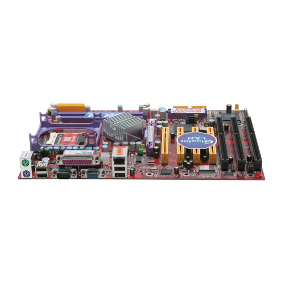
1-1 Mainboard SL-XP865G-3IG Layout ....................................9
1-2 Chipset System Block Diagram ........................................... 10
1-3 Mainboard Specification Table ............................................ 11
1-4 Mainboard Specifications .................................................... 12
1-4.1 CPU Socket ................................................................................... 12
1-4.2 System Chipsets ........................................................................... 12
1-4.3 Memory ......................................................................................... 12
1-4.4 AMI BIOS ..................................................................................... 12
1-4.5 Integrated Multiplexed AGP and DVO Interface .................. 13
1-4.6 Multi-I/O Functions .................................................................... 13
1-4.7 Advanced System Power Management .................................... 14
1-4.8 Gigabit LAN on board ................................................................ 14
1-4.9 Hardware Monitor on board ..................................................... 14
1-4.10 RS232/RS422/RS485 Interface supported ............................ 14
1-4.11 Form Factor ................................................................................ 14
Chapter 2 Hardware Setup ..................................... 16
2-1 CPU Installation with Socket 478B .................................... 17
2-1.1 To Identify a Pentium 4 CPU ..................................................... 17
2-1.2 CPU Installation with Socket 478B .......................................... 18
2-2 Pentium 4 CPU Fan Installation ......................................... 19
2-3 Memory Installation ............................................................. 20
2-3.1 To Install DDR SDRAM Module .............................................. 20
2-3.2 Dual Channel Memory Modules Setup .................................... 20
2-4 VGA / AGP 8X/4X Slot Installation .................................... 21
2-5 IDE Connectors Installation ................................................ 22
2-6 Serial ATA Connectors Installation .................................... 23
Contents
4
Advertisement
Table of Contents

Related Manuals for SOLTEK SL-XP865G-3IG


Summary of Contents for SOLTEK SL-XP865G-3IG
-
Page 1: Table Of Contents
Contents Contents Chapter 1 Specification ..........8 1-1 Mainboard SL-XP865G-3IG Layout ........9 1-2 Chipset System Block Diagram ........... 10 1-3 Mainboard Specification Table ..........11 1-4 Mainboard Specifications ............ 12 1-4.1 CPU Socket ................... 12 1-4.2 System Chipsets ................12 1-4.3 Memory .................. - Page 2 Contents 2-7 Floppy Drive Connector Installation ......... 24 2-8 ATX V2.03 Power Supply Installation ....... 25 2-9 PCI/ISA Slot Setup ..............26 2-10 Jumper Settings ..............28 2-10.0 How to tackle the Jumpers: ............. 29 2-10.1 JCLK1 & JCLK2: CPU Frequency Select ......29 2-10.2 JBAT1: Clear CMOS ..............
- Page 3 Contents Chapter 4 AMI BIOS Setup ........48 4-1 About BIOS Setup ..............49 4-2 To Run BIOS Setup ............... 49 4-3 About CMOS ................49 4-4 The POST ( Power On Self Test ) ........49 4-5 To Update BIOS ..............49 4-6 BIOS SETUP --- CMOS Setup Utility ........
- Page 4 Contents 4-6.7 Save Changes and Exit ............... 78 4-6.8 Discard Changes ( and Exit ) ............. 79 4-6.9 Load Optimal Defaults ............... 79 4-6.10 Discard Changes ................ 79 APPENDICES ............80 Appendix-1 Identify Mainboard Model Number ....81 Appendix-2 Technical Terms ............82...
-
Page 5: Chapter 1 Specification
SL-XP865G-3IG Chapter 1 Specification Introduction This mainboard features an integration of the powerful processor In- tel Pentium 4 and the North Bridge Intel 865G. The Intel P4 processor is a rapid execution engine supporting 800/533/400MHz system bus, while North Bridge Intel 865G is a high performance chipset providing... -
Page 6: Mainboard Sl-Xp865G-3Ig Layout
Chapter 1 Specification 1-1 Mainboard SL-XP865G-3IG Layout PS/2 K/B (underside) PS/2 Mouse (on top) Fan2 JKB1 USB1 mPGA478B (2 Ports +12V Power Intel RJ45 Intel 82865 (on top) USB2 (2 Ports) 865G Fan1 AGP1 8X/4X PCI 1 INTEL IDE1 IDE2... -
Page 7: Chipset System Block Diagram
SL-XP865G-3IG 1-2 Chipset System Block Diagram Intel Pentium 4 CPU (Hyper-Threading Included) System Bus 800/533/400MHz Intel Extreme DDR memory Intel Graphics 2 Interface System Connector Memory DDR 400/ North Bridge 333/266 865G AGP 8X/4X SDRAM AGP Slot DVO(digital) TV Out... -
Page 8: Mainboard Specification Table
Chapter 1 Specification 1-3 Mainboard Specification Table XP865G-3IG Specifications and Features Socket 478B for P4 CPU( HT CPU included) North Bridge Intel 865G, supporting 800/533/400MHz FSB South Bridge Intel ICH5 BIOS AMI BIOS Supporting Dual-channel DDR 400/333/266 Memory SDRAM, up to 2GB in 2 DIMM slots I/O Chip W83627HF, with Hardware Monitor Intel Extreme Graphics2 integrated in 865G... -
Page 9: Mainboard Specifications
SL-XP865G-3IG 1-4 Mainboard Specifications 1-4.1 CPU Socket ® CPU Socket 478B on board, supporting Intel Pentium 4 processors (including Intel Hyper-Threading CPUs) in 478-pin package for : -- 800/533/400MHz System Bus; -- Hyper-pipelined technology; -- Advanced dynamic execution; -- Advanced transfer cache;... -
Page 10: 1-4.5 Integrated Multiplexed Agp And Dvo Interface
Chapter 1 Specification 1-4.5 Integrated Multiplexed AGP and DVO Interface Integrated multiplexed AGP and DVO interface in 865G, supporting AGP performance and analog/Digital display: • One AGP slot on board, supporting Digital Video Out card or AGP8x/ 4x card for analog/digital display (TMDS,LVDS and TV-out) (See AGP Installation in Chapter 2 of this manual) •... -
Page 11: 1-4.7 Advanced System Power Management
• Hardware Monitor supported by W83627HF, providing monitoring and alarm for flexible desktop management of hardware voltage, tempera- tures and fan speeds. • Utility Software Soltek Hardware Monitor for displaying system status is enclosed in Support CD for user’s installation. 1-4.10 RS232/RS422/RS485 Interface supported •... - Page 12 Chapter 1 Specification Memo...
-
Page 13: Chapter 2 Hardware Setup
SL-XP865G-3IG Chapter 2 Hardware Setup To Get Things Ready for Hardware Setup ! 1. We recommend to install your CPU before any other components. For detailed installation instructions of processor, you can also refer to the pamphlet enclosed in your CPU package. -
Page 14: Cpu Installation With Socket 478B
Chapter 2 Hardware Setup 2-1 CPU Installation with Socket 478B 2-1.1 To Identify a Pentium 4 CPU Intel PENTIUM 4 2.80 GHz / 512 / 800 (Hyper-Threading CPU included) 3) System Bus 2) CPU L2 Cache 1) CPU Working Frequency On the heatsink side of a Pentium 4 CPU, there printed a line of figures to identify its specifications. -
Page 15: 2-1.2 Cpu Installation With Socket 478B
SL-XP865G-3IG 2-1.2 CPU Installation with Socket 478B This mainboard is built with CPU Socket 478B ( 478-pin) supporting the Intel Pentium 4 CPU: • Follow the steps described in this section to install the 478-pin Pen- tium 4 CPU into the on board Socket 478. -
Page 16: Pentium 4 Cpu Fan Installation
Chapter 2 Hardware Setup 2-2 Pentium 4 CPU Fan Installation Pentium 4 Fanbase CPU Fan Connector Press down 2 Spring Locks to lock fan to fanbase Connect Fan Connector to CPU FAN connector The above pictures are taken from sample mainboards as installation illustr- ation. -
Page 17: Memory Installation
SL-XP865G-3IG 2-3 Memory Installation 2-3.1 To Install DDR SDRAM Module • Make sure to unplug your power supply before adding or removing memory module. • Pay attention to the orientation of the DIMM slots. • DDR DIMM slot has 184 pins and one notch. Insert a DDR SDRAM vertically into the 184-pin slot with the notch-to-rib matching. -
Page 18: Vga / Agp 8X/4X Slot Installation
Chapter 2 Hardware Setup 2-4 VGA / AGP 8X/4X Slot Installation 1. To install on-board VGA, please connect your monitor directly to VGA connector on board. 2. To install AGP 8X/4X card / Digital-Video-Out(DVO) / TV Out display, please insert an AGP / DVO /TV Out card into the AGP slot. This AGP slot supports AGP 8X/4X card(analog), DVO card and TV Out card, respectively but not simultaneously. -
Page 19: Ide Connectors Installation
SL-XP865G-3IG 2-5 IDE Connectors Installation To install IDE Connector, you may connect the blue connector of IDE cable to the primary (IDE1) or secondary (IDE2) connector on board, and then connect the gray connector to your slave device and the black connector to your master device. -
Page 20: Serial Ata Connectors Installation
Chapter 2 Hardware Setup 2-6 Serial ATA Connectors Installation The Serial ATA is designed to improve the Parallel ATA with the capabil- ity of Hot Plug and offer a data bandwidth of 150Mbytes/second. It also reduce voltage and pin count and can be implemented with thin cables which improve the inner ventilaton of PC cases. -
Page 21: Floppy Drive Connector Installation
SL-XP865G-3IG 2-7 Floppy Drive Connector Installation To install FDC, you should connect the end of FDC cable with single connector to the board, and connect the other end with two connectors to the floppy drives. PS/2 K/B (underside) PS/2 Mouse... -
Page 22: Atx V2.03 Power Supply Installation
Chapter 2 Hardware Setup 2-8 ATX V2.03 Power Supply Installation +12V Power Connector +12V PWR OK PS/2 K/B (underside) PS/2 Mouse (on top) Fan2 JKB1 USB1 mPGA478B (2 Ports PS ON# +3.3V -12V +3.3V +3.3V +12V Power Intel Pin1 Pin11 RJ45 Intel 82865 (on top) -
Page 23: Pci/Isa Slot Setup
SL-XP865G-3IG 2-9 PCI/ISA Slot Setup • 3xISA slot and 4 PCI slots are designed on board to support PCI/ ISA card installation, which should all be assigned an IRQ for the signal transfer. Generally, the system BIOS will automatically assign an IRQ to every device it can detect at booting. - Page 24 Chapter 2 Hardware Setup • To see a map of your used and free IRQs in Windows 98, the Control Panel in My Computer, is incorporated with System icon. Click on System icon to reveal a Device Manager tab. Double-Clicking on a specific hardware device gives you a Resources tab which shows the Interrupt number and address.
-
Page 25: Jumper Settings
SL-XP865G-3IG 2-10 Jumper Settings The following diagrams show the locations and settings of jumper blocks on the mainboard. JCLK1& JCLK2: JBAT1 CPU Frequency Select Clear CMOS (default) AutoDetect 1-2 closed 200MHz 133MHz 100/ 100MHz (default) (FSB800) (FSB533) 133/ (FSB400) To hold data... -
Page 26: 2-10.0 How To Tackle The Jumpers
Chapter 2 Hardware Setup 2-10.0 How to tackle the Jumpers: A 2-pin Jumper A 3-pin Jumper If a pin-header (of 2 or more pins) is designed in such a way that its pins can be closed or linked together to The conductor inside the cap set up a specific function, this header links two header-pins together. -
Page 27: 2-10.2 Jbat1: Clear Cmos
SL-XP865G-3IG 2-10.2 JBAT1: Clear CMOS When you have problem with rebooting your system, you can clear CMOS data and restore it to default value. To clear CMOS with Jumper JBAT1, please follow the steps below: JBAT1 1. Power off system. -
Page 28: Other Connectors Configuration
Chapter 2 Hardware Setup 2-11 Other Connectors Configuration This section lists out all connectors configurations for users’ reference. 2-11.1 On Board Fan Connectors Void PS/2 K/B (underside) PS/2 Mouse Sensor (on top) Fan2 +12V JKB1 USB1 mPGA478B (2 Ports +12V Sensor Conn. -
Page 29: 2-11.3 Usb Ports And Usb Pin-Headers
SL-XP865G-3IG 2-11.3 USB Ports and USB Pin-headers This mainboard provides four USB ports on board supporting various USB devices. In addition, two USB pin-headers are added on board to provide expansion of four more optional USB ports by using two addi- tional USB cables. -
Page 30: 2-11.4 Chassis Panel Connectors
Chapter 2 Hardware Setup 2-11.4 Chassis Panel Connectors A : PS/2 Mouse F : COM1 Connector B : USB 1 (2 ports) G : VGA Connector C : LPT1 Port H : USB 2 (2 ports) D : RJ45 E : PS/2 Keyboard 2-11.5 LAN Connector on Back Panel One RJ45 connector is on Back Panel for LAN connection, supporting GiGabit Ethernet 10/100/1000Mb data transfer. -
Page 31: 2-11.6 Ps/2 Mouse And Ps/2 Keyboard
SL-XP865G-3IG 2-11.6 PS/2 Mouse And PS/2 Keyboard (PS/2 Mouse: On top of keyboard connector, green) 6 Void 5 Mouse Clock 4 VCC 3 GND 1 Mouse Data 2 Void 6 Void 5 Keyboard Clock 3 GND 4 VCC 2 Void... -
Page 32: 2-11.7 Com2 For Rs232/Rs422/Rs485 Setup
Chapter 2 Hardware Setup 2-11.7 COM2 for RS232/RS422/RS485 setup COM2 is a serial com port supporting RS232/RS422/RS485 interface serial data communications. JPIN1 to JPIN6 are jumpers designed to set COM2 for RS232/RS422/RS485 interface. COM2 PS/2 K/B (underside) COM2 PS/2 Mouse (on top) Pin Assignment Fan2... -
Page 33: 2-11.8 Complex Pin-Header
SL-XP865G-3IG 2-11.8 Complex Pin-header This complex Pin-header consists of the following connectors for vari- ous supports. When you have fixed the mainboard to the case, join the connectors of this Complex Pin-header to the case Front Panel. PWRBT# PLED- (1)Power Switch... - Page 34 Chapter 2 Hardware Setup (1) Power Switch Connector: Connection: Connected to a momentary button or switch. Function: Manually switching the system between “On” and “Soft Off”. Pressing the momentary button for more than 4 seconds will also turn the system off. (2) IR Connector (Infrared Connector): Connection: Connected to Connector IR on board.
-
Page 35: Chapter 3 Software Setup
SL-XP865G -3IG Chapter 3 Software Setup Drivers, Utilities and Software Installation • Support CD: This series of mainboards will be shipped with a Support CD which contains those necessary driver files, Application Softwares and some helpful utilities. It is a user-friendly, auto-run CD which will open itself up in a CD-ROM automatically. -
Page 36: Intel Chipset Software Installation Utility
Chapter 3 Software Setup 3-2 Intel Chipset Software Installation Utility 1. Following the procedures of opening the Support CD, click to “ Install Intel Chipset software installation Utility” to proceed. 2. The Intel Service Pack InstallShield Wizard will pop up to guide you to the Intel Service pack installation. -
Page 37: Directx Installation (For Win98Se/Me)
SL-XP865G -3IG 3-3 DirectX Installation (for Win98se/Me) Following the installation of INF, you have to restart system so that your system can be reconfigured with the driver just installed. When restarting procedures finish, please open the Support CD with your CD- ROM to enter the Main Installation Menu. -
Page 38: Graphics Driver Installation
Chapter 3 Software Setup 3-4 Graphics Driver Installation Following the installation of IAA, you have to restart system so that your system can be reconfigured with the utility. When restarting pro- cedures finish, please open the Support CD with your CD-ROM to en- ter the Main Installation Menu. -
Page 39: To Install Hardware Monitor Utility
SL-XP865G -3IG 3-5 To Install Hardware Monitor Utility 3-5.1 Installation Hardware Monitor is built on this mainboard. Its installation is pro- grammed to a fully automated mode on Windows 9X/Me/NT4/2000/ XP. Users can follow the model installation below for its installation on various Windows System. -
Page 40: 3-5.2 Verification
Chapter 3 Software Setup 3-5.2 Verification 1. After installing Soltek Hardware Monitor, double click “SoltekHM” icon on the desktop to open the main window of the Soltek Hardware Doctor. 2.Then the pop-up screen will show all information about CPU Temperature, Fan Speed and various Voltages. -
Page 41: To Install Lan Drivers
SL-XP865G -3IG 3-6 To Install LAN Drivers 3-6.1 Intel 82547EI LAN driver on Windows ME / 2000 / XP The LAN driver contained in the Support CD is not included in the Autorun Menu. To install Intel 82547EI LAN driver on Windows 2000 / XP, please follow the steps shown below: 1. -
Page 42: 3-6.2 Intel 82547Ei Lan Driver On Windows 9X
Chapter 3 Software Setup 3-6.2 Intel 82547EI LAN driver on Windows 9X The LAN driver contained in the Support CD is not included in the Autorun Menu. To install Intel 82547EI LAN driver on Windows 9X, please follow the steps shown below: 1. - Page 43 SL-XP865G -3IG 6. As illustrated in the picture below, check the item “Specify a location” and click the “Browse” button to find out the correct path for the driver. Supposing your CD-ROM drive is Drive E, please type: E:\Driver\Network\Intel_LAN\GIGABPS\Win9x_me\Win_98me into the blank bar.
-
Page 44: To Install Usb 2.0 Driver For Windows 2000/Xp
Chapter 3 Software Setup 3-7 To Install USB 2.0 Driver for Windows 2000/XP USB V2.0 with its 480Mb/s transfer rate supports operating system Windows 2000 and Windows XP via the Windows 2000 and Windows XP Service Pack. For archieving Intel USB 2.0 support, users should install the latest Service Pack for Windows 2000 or Windows XP. -
Page 45: Chapter 4 Ami Bios Setup
4-5 To Update BIOS 4-6 BIOS Setup Attention: The BIOS Setup is subject to constant update without further notice to users. It is necessary for users to update the onboard BIOS by the latest BIOS version provided in our web site: www.soltek.com.tw... -
Page 46: About Bios Setup
Chapter 4 BIOS Setup 4-1 About BIOS Setup BIOS setup is an interactive BIOS program that you need to run when: 1. Changing the hardware of your system. (For example: installing a new Hard Disk etc.) 2. Modifying the behavior of your computer. (For example: changing the system time or date, or turning special features on or off etc.) 3. - Page 47 SL-XP865G -3IG • It is highly recommended that you save a copy of the original mainboard BIOS along with a Flash EPROM Programming utility (amiflash.exe) to a bootable floppy disk so that you can reinstall the BIOS when in need. •...
-
Page 48: Bios Setup
Chapter 4 BIOS Setup 4-6 BIOS SETUP --- CMOS Setup Utility 4-6.1 CMOS Setup Utility This mainboard comes with the AMI BIOS from American Megatrends Inc. Enter the CMOS Setup Utility Main Menu by: 1. Turn on or reboot your system. After a series of diagnostic checks, the following message will appear: PRESS <Del>... - Page 49 <F9>: “Optimized Defaults” alows user to load Optimal Defaults or not. Attention: The BIOS Setup is subject to constant update without further notice to users. It is necessary for users to update the onboard BIOS by the latest BIOS version provided in our web site: www.soltek.com.tw...
-
Page 50: 4-6.2 Standard Bios Features
Chapter 4 BIOS Setup 4-6.2 Standard BIOS Features “Standard BIOS Features” allows users to configure Time and Date. This menu also displays system information. Run the Standard BIOS Features as follows: Choose “Standard BIOS Features” from the Main Menu and press <Enter>. -
Page 51: 4-6.3 Advanced Bios Features
SL-XP865G -3IG 4-6.3 Advanced BIOS Features Advanced BIOS Features allows user to configure HDD, Floppy, Serial Port, Parallel Port etc..Run the Advanced BIOS Features as follows: Choose “Advanced BIOS Features” from the Main Menu and a screen with a list of options will appear: CMOS Setup Utility - Copyright (C) 1985-2002, American Megatrends, Inc. -
Page 52: 4-6.3.1 Cpu Configuration
Chapter 4 BIOS Setup 4-6.3.1 CPU Configuration Choose “CPU Configuration” in “Advanced BIOS Features” and press <Enter>. The following sub-screen will appear for configuration: CPU Configuration Help Item Configure advanced CPU settings Sets the ratio between CPU Manufacturer : Intel core clock and the FSB Brand String : Intel(R) Pentium (R) 4 CPU 1500MHz Frequency. -
Page 53: 4-6.3.2 Ide Configuration
SL-XP865G -3IG 4-6.3.2 IDE Configuration Choose “IDE Configuration” in “Advanced BIOS Features” and press <Enter>. The following sub-screen will appear for IDE Devices configuration: IDE Configuration Help Item IDE Configuration IDE Configuration P/S-ATA (Auto) S-ATA Running Enhanced Mode P-ATA Channel Selection Both S-ATA Ports Definition P0-3rd./P1-4th... - Page 54 Chapter 4 BIOS Setup 4-6.3.2-2 Primary/Secondary IDE Master/Slave and Third/Fourth IDE Master Primary IDE Master Hard Disk Primary IDE Slave ATAPI CDROM Secondary IDE Master Not Detected Secondary IDE Slave Not Detected Third IDE Master Not Detected Fourth IDE Master Not Detected If any IDE device is detected in any one of the above items press <Enter>...
-
Page 55: 4-6.3.3 Floppy Configuration
SL-XP865G -3IG 4-6.3.2-3 Hard Disk Write Protect Hard Disk Write Protect Allows you to Enabled / Disable(default) Hard Disk Write Protection 4-6.3.2-4 IDE Detect Time Out IDE Detect Time Out(Sec) Allows you to set time out for IDE Detection. Choices: 0 - 35 seconds in 5 seconds stepping 4-6.3.2-5 ATA(P) 80Pin Cable Detection ATA(PI) 80Pin Cable Detection Allows you to select ATA(PI) devices for 80Pin Cable Detection. -
Page 56: 4-6.3.4 Super Io Configuration
Chapter 4 BIOS Setup 4-6.3.4 Super IO Configuration Choose “SuperIO Configuration” in “Advanced BIOS Features” and press <Enter>. The following sub-screen will appear for configuration: SuperIO Configuration Help Item Configure Win627 Super IO Chipset OnBoard Floppy Controller Enabled Allows BIOS to Enable or Serial Port1 Address 3F8/IRQ4 Disable Floppy Controller. - Page 57 SL-XP865G -3IG OnBoard CIR Port Allows you to set the onboard CIR Port. Choices: Disabled; 2E0; 3E0 Disabled: Onboard CIR port disabled; 2E0/3E0: If 2E0 chosen, CIR Port IRQ is provided for configuration: CIR Port IRQ: IRQ3; IRQ4; IRQ10; IRQ11 Parallel Port Address Allows you to configure Parallel Port Address.
-
Page 58: 4-6.3.5 Hardware Health Configuration
Chapter 4 BIOS Setup 4-6.3.5 Hardware Health Configuration Choose “Hardware Health Configuration” in “Advanced BIOS Features” and press <Enter>. The following sub-screen will appear for configuration: Hardware Health Configuration Hardware Health Configuration Help Item System Temperature : 34˚C/93˚F Enables Hardware Health Monitoring Device. -
Page 59: 4-6.3.6 Acpi Configuration
SL-XP865G -3IG 4-6.3.6 ACPI Configuration Choose “ACPI Configuration” in “Advanced BIOS Features” and press <Enter>. The following sub-screen will appear for ACPI configuration: ACPI Configuration Help Item ACPI Settings Enables Hardware ACPI General ACPI Configuration Press Enter support for Operating System. - Page 60 Chapter 4 BIOS Setup Advanced ACPI Configuration: To press< Enter > on Advanced ACPI Configuration will reveal the following item(s). ACPI 2.0 Support Allows you to enable / disable ACPI (Advanced Con- figuration and Power Interface) 2.0 Support function. Choices: Yes; No ACPI APIC Support Allows you to enable / disable ACPI APIC (Advanced Programmable Interrupt Controller) Support function.
-
Page 61: 4-6.3.7 Usb Configuration
SL-XP865G -3IG 4-6.3.7 USB Configuration Choose “USB Configuration” in “Advanced BIOS Features” and press <Enter>. The following sub-screen will appear for configuration: USB Configuration Help Item USB Configuration Enable USB host Module Version - 2.23.2-7.4 controllers. USB Devices Enabled : None USB Function 8 USB Ports... -
Page 62: 4-6.3.8 Power Management
Chapter 4 BIOS Setup If users have installed USB Devices on the system, these items will appear as below for further configuration. USB Mass Storage Press “Enter” to view its submenu shown below. Device Config USB Mass Storage To select number of seconds POST waits for the Reset Delay USB mass storage device after start unit command. -
Page 63: 4-6.3.9 Clock Configuration
SL-XP865G -3IG Hard Disk Power Down Mode Allows you to select the Hard Disk Power Down Mode. Choices: Disabled; Standby; Suspend Standby Time Out (Minute) To set the duration of Standby Time Out. Choices: Disabled; 1; 2; 4; 8; 10; 20; 30; 40; 50; 60 Suspend Time Out (Minute) To set the duration of Suspend Time Out. -
Page 64: 4-6.4 Advanced Chipset Features
Chapter 4 BIOS Setup 4-6.4 Advanced Chipset Features Run the Advanced Chipset Features as follows: Choose “Advanced Chipset Features” from the Main Menu and a list of option will appear: CMOS Setup Utility - Copyright (C) 1985-2002, American Megatrends, Inc. Advanced Chipset Features Help Item Advanced Chipset Settings... - Page 65 SL-XP865G -3IG DRAM CAS# Latency With SDRAM Timing by SPD disabled, you can se- lect the SDRAM CAS# (Column Address Strode)la- tency manually. Choices: 2 Clocks; 2.5 Clocks; 3 Clocks DRAM RAS# With SDRAM Timing by SPD disabled, you can se- Precharge lect the SDRAM RAS# (Row Address Strode) Precharge cycle manually.
- Page 66 Chapter 4 BIOS Setup Boot Display Device Allows you to select the Boot Display device. Choices: Auto (default); CRT; TV; EFP; LFP; CRT+EFP; CRT+LFP Flat Panel Type Allows you to select the flat panel type. Choices: 640x480LVDS;800x600LVDS; 1024x768LVDS; 1280x1024LVDS; 1400x1050LVDS;1600x1200LVDS; 640x480CMOS;...
-
Page 67: 4-6.5 Pci/Pnp Resource Management
SL-XP865G -3IG 4-6.5 PCI/PNP Resource Management PCI/PNP Resource Management allows you to modify the system’s power saving functions. Choose “PCI/PNP Resource Management” from the Main Menu and a screen with a list of options will appear: CMOS Setup Utility - Copyright (C) 1985-2002, American Megatrends, Inc. PCI/PNP Resource Management Help Item Advanced PCI/PNP Settings... - Page 68 Chapter 4 BIOS Setup Allocate IRQ to PCI Allows you to assign IRQ to PCI VGA card if card requests IRQ. Choices: Yes(default); No Palette Snooping This option allows the BIOS to preview VGA status, and to modify the information delivered from the feature Connector of the VGA card to MPEG card.
-
Page 69: 4-6.6 Boot Configuration Setup
SL-XP865G -3IG 4-6.6 Boot Configuration Setup Boot Configuration Setup allows you to modify the system’s boot settings. Choose “Boot Configuration Setup” from the Main Menu and a screen with a list of options will appear: CMOS Setup Utility - Copyright (C) 1985-2002, American Megatrends, Inc. Boot Configuration Setup Help Item Boot Settings... -
Page 70: 4-6.6.1 Boot Settings Configuration
Chapter 4 BIOS Setup 4-6.6.1 Boot Settings Configuration Choose “Boot Settings Configuration” in “Boot Configuration Setup” and press <Enter>. The following items will appear for onfiguration: Boot Configuration Setup Help Item Boot Settings Configure Settings Quick Boot Enabled during System Boot. Quiet Boot Disabled AddOn ROM Display Mode... -
Page 71: 4-6.6.2 Boot Device Priority
SL-XP865G -3IG PS/2 Mouse Support Enabled (default), PS/2 mouse is supported. Disabled, PS/2 Mouse is not supported. If “Auto” is set, the system will auto detect the PS/2 Mouse. Wait For ‘F1’ If Error Allows you to hit F1 key when errors occur. Choices: Enabled(default);... -
Page 72: 4-6.7 Boot Security Features
Chapter 4 BIOS Setup 4-6.7 Boot Security Features Boot Security Features allows you to modify the system’s boot security settings. Choose “Boot Security Features” from the Main Menu and a screen with a list of options will appear: CMOS Setup Utility - Copyright (C) 1985-2002, American Megatrends, Inc. Boot Security Features Security Settings Help Item... -
Page 73: 4-6.7.3 Change Supervisor Password
SL-XP865G -3IG 4-6.7.3 Change Supervisor Password This option allows you to set a new Supervisor password for the system: 1. Choose “Change Supervisor Password” in the “BIOS Security Fea- tures” and press <Enter>. Then the following message appears: [ Enter new supervisor password ] 2. -
Page 74: 4-6.7.4 Change User Password
Chapter 4 BIOS Setup 4-6.7.4 Change User Password This option allows you to set a new User password for the system: 1. Choose “Change User Password” in the “BIOS Security Features” and press <Enter>. Then the following message appears: [ Enter New Password ] 2. -
Page 75: 4-6.7.6 Boot Sector Virus Protection
SL-XP865G -3IG Password Check Allows you to set BIOS to check up password with a password prompt at BIOS Setup or whenever re- starting system. This option will appear when you have set Supervisor Password or User Password. Choices: Setup (default); Always 4-6.7.6 Boot Sector Virus Protection Boot Sector Virus When enabled, you receive a warning message if a... - Page 76 Chapter 4 BIOS Setup 4-6.8 Discard Changes ( and Exit ) Discard Changes option allows you to exit (or not exit) the Setup Utility without saving the modifications that you have specified. Highlight this option on the Main Menu and press <Enter> and the following message appears: [ Discard Changes (and exit setup?)] [OK]...
Need help?
Do you have a question about the SL-XP865G-3IG and is the answer not in the manual?
Questions and answers