Table of Contents
Advertisement
Available languages
Available languages
Quick Links
Advertisement
Chapters
Table of Contents

Related Manuals for JUMO miroVIEW


Summary of Contents for JUMO miroVIEW
- Page 1 JUMO miroVIEW Smarter Digitalanzeiger mit Grenzwertüberwachung Smart digital indicator with limit value monitoring function Kurzanleitung Brief Instructions 70159001T97Z000K000 V1.00/DE-EN/00772546/2022-12-01...
- Page 3 JUMO miroVIEW Smarter Digitalanzeiger mit Grenzwertüberwachung Kurzanleitung 70159000T97Z000K000 V1.00/DE/2022-12-01...
- Page 4 Weitere Informationen und Downloads qr-701590-de.jumo.info...
-
Page 5: Table Of Contents
Inhalt Inhalt Sicherheit ........... 5 Symbole und Signalwörter . - Page 6 Inhalt Wartung, Reinigung, Störungsbeseitigung ..... . . 24 Wartung..............24 Reinigung .
-
Page 7: Sicherheit
Sicherheit 1 Sicherheit Symbole und Signalwörter Allgemein Diese Anleitung enthält Hinweise, die Sie zu Ihrer eigenen Sicherheit sowie zur Vermeidung von Sach- schäden beachten müssen. Diese Hinweise sind durch Zeichen unterstützt und werden in dieser Anlei- tung wie gezeigt verwendet. Lesen Sie diese Anleitung, bevor Sie das Gerät in Betrieb nehmen. -
Page 8: Bestimmungsgemäße Verwendung
1 Sicherheit Bestimmungsgemäße Verwendung Das Gerät ist für die Verwendung in industrieller Umgebung bestimmt, wie in den technischen Daten spezifiziert. Eine andere oder darüber hinausgehende Nutzung gilt als nicht bestimmungsgemäß. Das Gerät ist entsprechend den gültigen Normen und Richtlinien sowie den geltenden sicherheitstech- nischen Regeln gebaut. -
Page 9: Qualifikation Des Personals
1 Sicherheit Qualifikation des Personals Dieses Dokument enthält die erforderlichen Informationen für den bestimmungsgemäßen Gebrauch des darin beschriebenen Gerätes. Es wendet sich an technisch qualifiziertes Personal, das speziell ausgebildet ist und einschlägiges Wis- sen auf dem Gebiet der Automatisierungstechnik besitzt. Die Kenntnis und das technisch einwandfreie Umsetzen der in der mitgelieferten Technischen Doku- mentation enthaltenen Sicherheitshinweise und Warnungen sind Voraussetzungen für die gefahrlose Montage, Installation und Inbetriebnahme sowie für die Sicherheit während des Betriebes des beschrie-... -
Page 10: Beschreibung
Beschreibung 2 Beschreibung Gesamtübersicht Das Gerät ist in folgenden Ausführungen lieferbar: (10) Typ 701591, Typ 701590, Frontblende 88 mm Frontblende 68 mm Dichtung Adapterblech Schalttafelbefestiger Frontblende mit Folientastatur, Kapitel 6.1 „Anzeige- und Bedienelemente“, Seite 21 Display Typenschild, Kapitel 2.3.1 „Typenschild“, Seite 9 Rückansicht mit Leiterplattensteckern, Kapitel 5.2 „Anschlusselemente und Stecker“,... -
Page 11: Geräteausführung Identifizieren
2 Beschreibung Die Bedienung, Parametrierung und Konfiguration erfolgt über eine Folientastatur mit vier Tasten. Mit Hilfe des Setup-Programms ist das Gerät komfortabel mit einem PC konfigurierbar. Während der Konfi- guration über die USB-Schnittstelle ist keine separate Spannungsversorgung erforderlich (USB-powe- red). Geräteausführung identifizieren 2.3.1 Typenschild... -
Page 12: Bestellangaben
2 Beschreibung 2.3.2 Bestellangaben Grundtyp 701590 Typ 701590 mit 1 Relais, Format (Ø 60 x 80) mm 701591 Typ 701591 mit 1 Relais, Format (Ø 80 x 80) mm Ausführung Standardausführung Kundenspezifisch angepasste Hardware Kundenspezifisch angepasste Software Kundenspezifisch angepasste Hard- und Software Eingang (Messeingangsgruppe) 1 Widerstandsthermometer Pt100, Pt1000 in Zweileiterschaltung, 1 Digitaleingang Ausgang... -
Page 13: Warenannahme, Lagerung Und Transport
Beschreibung des aufgetretenen Fehlers Das Reparatur-Begleitschreiben (Begleitschreiben für Produktrücksendungen) kann im Internet von der Homepage des Herstellers heruntergeladen werden: http://produktruecksendung.jumo.info Schutz gegen Elektrostatische Entladung (ESD) (ESD = Electro Static Discharge) Zur Vermeidung von ESD-Schäden müssen elektronische Baugruppen oder Bauteile in ESD-geschütz- ter Umgebung gehandhabt, verpackt und gelagert werden. -
Page 14: Entsorgung
3 Warenannahme, Lagerung und Transport Entsorgung Entsorgung des Gerätes ENTSORGUNG! Das Gerät oder ersetzte Teile gehören nach Beendigung der Nutzung nicht in die Mülltonne, denn es besteht aus Werkstoffen, die von darauf spezialisierten Recycling-Betrieben wiederverwendet werden können. Das Gerät sowie das Verpackungsmaterial ordnungsgemäß und umweltschonend entsorgen lassen. Hierbei die landesspezifischen Gesetze und Vorschriften zur Abfallbehandlung und Entsorgung beach- ten. -
Page 15: Montage
Montage 4 Montage Montagehinweise WARNUNG! Das Gerät ist nicht für die Verwendung in explosionsgefährdeten Bereichen vorgesehen. Es besteht die Gefahr einer Explosion. Gerät nur außerhalb explosionsgefährdeter Bereiche einsetzen. Montageort Das Gerät ist für den Einbau in einen Schalttafelausschnitt innerhalb eines geschlossenen Schalt- schranks vorgesehen. -
Page 16: Abmessungen
4 Montage Abmessungen 4.2.1 Typ 701590 Ø 68 60,6... -
Page 17: Typ 701591
4 Montage 4.2.2 Typ 701591 Ø 88 60,6 4.2.3 Einbaumaße Schalttafel- Einbautiefe ohne Mindestabstände der Schaltta- ausschnitt Ø Dichtung felausschnitte (bei Dicht-an- dicht-Montage) horizontal vertikal 701590 60,5 +0,5 mm 80 mm 15 mm 30 mm 701591 80,5 +0,5 mm... -
Page 18: Schalttafeleinbau
4 Montage Schalttafeleinbau VORSICHT! Gerätefront und Gehäuse haben unterschiedliche Schutzarten! Die Schutzart IP65 (frontseitig) ist nur bei gleichmäßig anliegender Dichtung gewährleistet. Den Befestigungsrahmen bzw. die beiden Befestigungselemente wie in der Abbildung gezeigt ver- wenden und auf gleichmäßige Befestigung achten! Schalttafelbefestiger Schalttafel Schalttafelausschnitt... -
Page 19: Elektrischer Anschluss
Elektrischer Anschluss 5 Elektrischer Anschluss Installationshinweise Anforderungen an das Personal • Arbeiten am Gerät dürfen nur im beschriebenen Umfang und ebenso wie der elektrische Anschluss ausschließlich von Fachpersonal durchgeführt werden. • Vor dem Stecken und Ziehen von Anschlussleitungen muss sichergestellt sein, dass die durchfüh- rende Person elektrostatisch entladen ist (z. -
Page 20: Anschlusselemente Und Stecker
5 Elektrischer Anschluss GEFAHR! Lebensgefahr durch Stromschlag Verletzungsgefahr beim Berühren von stromführenden Teilen! Nur eine qualifizierte Elektrofachkraft darf Anschluss und Installation eines nicht steckerfertigen elektrischen Geräts durchführen. Vor Arbeiten an Anlage oder Gerät die Spannung abschalten und gegen Wiedereinschalten sichern. ... -
Page 21: Anschlussplan
5 Elektrischer Anschluss Anschlussplan VORSICHT! Gefahr von Geräteschäden Wenn das Gerät nicht mit der auf dem Typenschild angegebenen Spannung versorgt wird, führt das un- ter Umständen zur Zerstörung des Geräts. Spannungsversorgung ausschließlich mit einer Spannungsquelle herstellen, die den Angaben auf dem Typenschild entspricht. -
Page 22: Galvanische Trennung
5 Elektrischer Anschluss Galvanische Trennung AC 3000 V AC 3000 V Die Spannungsangaben entsprechen den Funktionale galvanische Trennung zum Prüfwechselspannungen (Effektivwerte) Anschluss von SELV- oder PELV- gemäß DIN EN 61010-1 (VDE 0411- Stromkreisen 1):2020-03 Relaisausgang USB-Schnittstelle oder Spannungsversorgung DC 12 V bis 24 V Spannungsversorgung 230 V, 48 bis 63 Hz 115 V, 48 bis 63 Hz Digitaleingang... -
Page 23: Bedienung
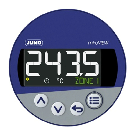
Bedienung 6 Bedienung Die primäre Bedienerschnittstelle des Gerätes ist die frontseitige Folientastatur mit dem Display. Sie er- möglicht eine schnelle Bedienung und Konfiguration am Einbauort des Gerätes. Nicht relevante Para- meter, Unterparameter, Selektor- und Auswahleinstellungen blendet die Software für die Bedienung am Gerät aus, wenn •... -
Page 24: Bedienübersicht
6 Bedienung Menu/OK (Hauptmenü aufrufen, in Unter- Back (im Menü: zurück zur vorherigen Me- menü/Ebene wechseln, in Editiermodus nüebene, Editiermodus ohne Änderung ver- wechseln, Editiermodus mit Änderung ver- lassen; in Grundstellung: konfigurierbare lassen) Funktion) Down (im Menü: Wert verringern, nächsten Up (im Menü: Wert vergrößern, vorherigen Menüpunkt oder Parameter auswählen) Menüpunkt oder Parameter auswählen) -
Page 25: Sprachauswahl
6 Bedienung Sprachauswahl Nach dem erstmaligen Einschalten des Gerätes kann der Anwender entweder die blinkend dargestellte Sprache mit „OK“ bestätigen oder mit den Tasten „Up“/„Down“ eine andere Sprache auswählen und dann mit „OK“ bestätigen. Nach Übernahme einer Sprache setzt das Gerät diesen Parameter automatisch auf „AUS“, so dass beim erneuten Einschalten keine Sprachauswahl erforderlich ist. -
Page 26: Wartung, Reinigung, Störungsbeseitigung
Wartung, Reinigung, Störungsbeseitigung 7 Wartung, Reinigung, Störungsbeseitigung Wartung Das Gerät ist wartungsfrei. Bei Schäden, z.B. durch Transport, Wartung oder bei Defekten im Betrieb, dürfen keine Reparaturen am Gerät vorgenommen werden. Wenn das Gerät göffnet wurde, erlischt der Gewährleistungsanspruch. Das Gerät im Schadenfall an den zuständigen Servicepartner senden. Siehe Rückseite dieser Betriebs- anleitung. -
Page 27: Technische Daten
Technische Daten 8 Technische Daten Analogeingang Widerstandsthermometer Bezeichnung Norm Anschlussart Messbereich Genauig- Mess- keit strom ≤ 0,25 % 500 μA Pt100 DIN EN 60751:2008 ITS-90 2-Leiter -200 bis +600 °C IEC 60751:2008 ≤ 0,25 % 100 μA Pt1000 DIN EN 60751:2009 ITS-90 2-Leiter -200 bis +600 °C... -
Page 28: Elektrische Daten
8 Technische Daten Elektrische Daten Spannungsversorgung AC 230 V +10/-15 %, 48 bis 63 Hz entsprechend der bestellten Aus- AC 115 V +10/-15 %, 48 bis 63 Hz führung DC 12 bis 24 V, ±15 % SELV Elektrische Sicherheit nach DIN EN 61010, Teil 1 Überspannungskategorie II bis 300 V Netzspannung, Verschmutzungsgrad 2 Leistungsaufnahme... -
Page 29: Gehäuse
8 Technische Daten Gehäuse Gehäuseart Kunststoffgehäuse für den Schalttafeleinbau nach IEC 61554 (Verwendung in Innenräumen), kobaltblau RAL 5013 Gehäusefront Folientastatur, oberere Schräge kobaltblau RAL 5013, untere Schräge silbergrau RAL 7001 Schalttafelstärke 1 bis 10 mm Gehäusebefestigung in Schalttafel unter Verwendung des mitgelieferten Befestigungsrahmens bzw. der beiden Befestigungselemente Gebrauchslage beliebig... - Page 30 8 Technische Daten...
- Page 32 JUMO GmbH & Co. KG Moritz-Juchheim-Straße 1 Technischer Support Deutschland: 36039 Fulda, Germany Telefon: +49 661 6003-727 Telefon: +49 661 6003-9135 Telefax: +49 661 6003-508 Telefax: +49 661 6003-881899 E-Mail: mail@jumo.net E-Mail: support@jumo.net Internet: www.jumo.net Lieferadresse: Mackenrodtstraße 14 36039 Fulda, Germany...
- Page 33 JUMO miroVIEW Smart digital indicator with limit value monitoring function Brief Instructions 70159000T97Z000K000 V1.00/EN/2022-12-01...
- Page 34 Further information and downloads qr-701590-en.jumo.info...
- Page 35 Contents Contents Safety ............5 Symbols and signal words .
- Page 36 Contents Maintenance, cleaning, troubleshooting......24 Maintenance .............24 Cleaning .
-
Page 37: Safety
Safety 1 Safety Symbols and signal words General This manual contains information that must be observed in the interest of your own safety and to avoid material damage. This information is supported by symbols which are used in this manual as indicated. Please read this manual before starting up the device. -
Page 38: Safety Information
1 Safety The device has been manufactured in compliance with applicable standards and directives as well as the applicable safety regulations. Nevertheless, improper use may lead to personal injury or material damage. To avoid danger, only use the device: • For the intended use •... -
Page 39: Qualification Of Personnel
1 Safety Qualification of personnel This document contains the necessary information for the intended use of the device to which it relates. It is intended for staff with technical qualifications who have been specially trained and have the appro- priate knowledge in the field of automation technology. The appropriate level of knowledge and the technically fault-free implementation of the safety informa- tion and warnings contained in the technical documentation provided are prerequisites for risk-free mounting, installation, and startup as well as for ensuring safety when operating the described modules. -
Page 40: Description
Description 2 Description General overview The device is available in the following versions: (10) Type 701591, Type 701590, front panel 88 mm front panel 68 mm Seal Adapter plate Panel fasteners Front panel with membrane keyboard, chapter 6.1 "Display and control elements", Page 21 Display Nameplate, chapter 2.3.1 "Nameplate",... -
Page 41: Identifying The Device Version
2 Description Operation, parameterization, and configuration are carried out via a membrane keyboard with four keys. The setup program on a PC allows the device to be configured without any problems. No separate volt- age supply is required when configuring via the USB interface (USB-powered). Identifying the device version 2.3.1 Nameplate... -
Page 42: Order Details
2 Description 2.3.2 Order details Basic type 701590 Type 701590 with 1 relay, format (Ø 60 x 80) mm 701591 Type 701591 with 1 relay, format (Ø 80 x 80) mm Version Standard version Customized hardware Customized software Customized hardware and software Input (measurement input group) 1 RTD temperature probe Pt100, Pt1000 in two-wire circuit, 1 digital input Output... -
Page 43: Acceptance Of Goods, Storage, And Transport
Description of the error that has occurred The accompanying letter for repair (supplementary sheet for product returns) can be downloaded online from the manufacturer's website: http://productreturn.jumo.info Protection against electrostatic discharge (ESD) (ESD = electrostatic discharge) To prevent damage due to ESD, electronic modules or components must be handled, packaged, and stored in an ESD-protected environment. -
Page 44: Disposal
3 Acceptance of goods, storage, and transport Disposal Disposing of the device DISPOSAL! Devices and/or replaced parts should not be placed in the refuse bin at the end of their service life as they consist of materials that can be recycled by specialist recycling plants. Dispose of the device and the packaging material in a proper and environmentally friendly manner. -
Page 45: Mounting
Mounting 4 Mounting Installation instructions WARNING! The device is not designed for use in potentially explosive areas. Explosion hazard. Only deploy the device outside of potentially explosive areas. Mounting site The device is designed for installation in a panel cut-out within a closed switch cabinet. The front of the device and housing have different protection types (see technical data). -
Page 46: Dimensions
4 Mounting Dimensions 4.2.1 Type 701590 Ø 68 60,6... -
Page 47: Type 701591
4 Mounting 4.2.2 Type 701591 Ø 88 60,6 4.2.3 Installation dimensions Type Panel cut-out Ø Mounting depth Minimum spacing of panel cut- without seal outs (for close mounting) Horizontal Vertical 701590 60.5 +0.5 mm 80 mm 15 mm 30 mm 701591 80.5 +0.5 mm... -
Page 48: Panel Mounting
4 Mounting Panel mounting CAUTION! The front of the device and housing have different protection types! The protection type IP65 (front-side) is only guaranteed if the seal is flush and even. Use the mounting frame or both mounting elements as shown in the figure and ensure an even at- tachment! Panel fasteners Panel... -
Page 49: Electrical Connection
Electrical connection 5 Electrical connection Installation notes Requirements for personnel • Work on the device must only be carried out to the extent described and, like the electrical connec- tion, only by qualified personnel. • Before plugging and unplugging connecting cables, it must be ensured that the acting person is elec- trostatically discharged (by touching grounded metallic parts, for example). -
Page 50: Connection Elements And Connectors
5 Electrical connection DANGER! Risk to life due to electric shock Risk of injury when touching live parts! Only qualified electricians are allowed to connect and install an electrical device that is not already ready to use. Before working on the system or device, switch off the voltage and secure it so that it cannot switch on again. -
Page 51: Connection Diagram
5 Electrical connection Connection diagram CAUTION! Risk of device damage If the device is not supplied with the voltage specified on the nameplate, this could cause damage to the device. Only supply voltage from a voltage source that matches the specifications on the nameplate. CAUTION! In unfavorable conditions, the temperature may exceed 60 °C at the terminals. -
Page 52: Galvanic Isolation
5 Electrical connection Galvanic isolation AC 3000 V AC 3000 V The voltage specifications correspond to the Functional galvanic isolation for test voltages (alternating voltage, rms val- connecting SELV or PELV ues) electrical circuits according to DIN EN 61010-1 (VDE 0411- 1):2020-03 Relay output USB interface... -
Page 53: Operation
Operation 6 Operation The primary operator interface on the device is the front side membrane keyboard with the display. It enables users to quickly operate and configure the device at the device installation location. Non-rele- vant parameters, sub-parameters, selector and selection settings are hidden by the software for opera- tion of the device if •... -
Page 54: Operating Overview
6 Operation Down (in the menu: reduce value, select Up (in the menu: increase value, select pre- next menu item or parameter) vious menu item or parameter) Timer (illuminated = on, flashing = started), Switch position of the digital outputs (yellow Temperature Unit = active) 6.1.1... - Page 55 6 Operation If, at a later point, another user is also to have the option of selecting a language, the configuration pa- rameter "LANGUAGE SELECT. POWER ON" can be set to "ON" in the menu (Configuration > System data). The language of the device texts can be changed at any time in the configuration settings. This is irre- spective of the language selection after switching on the device.
-
Page 56: Maintenance, Cleaning, Troubleshooting
Maintenance, cleaning, troubleshooting 7 Maintenance, cleaning, troubleshooting Maintenance The device is maintenance-free. In the event of damage, e.g. due to transport, maintenance, or faults during operating, it is not permissible to carry out repairs on the device. If the device is opened up, the warranty claim becomes void. -
Page 57: Technical Data
Technical data 8 Technical data Analog input RTD temperature probe Designation Standard Connection Measuring range Accuracy Measur- type ing cur- rent ≤ 0.25 % 500 μA Pt100 DIN EN 60751:2008 ITS-90 Two-wire -200 to +600 °C IEC 60751:2008 ≤ 0.25 % 100 μA Pt1000 DIN EN 60751:2009... -
Page 58: Electrical Data
8 Technical data Electrical data Voltage supply AC 230 V -15/+10 %, 48 to 63 Hz according to the ordered ver- AC 115 V -15/+10 %, 48 to 63 Hz sion DC 12 to 24 V, -15/+15 % SELV Electrical safety acc. -
Page 59: Case
8 Technical data Case Case type Plastic case for panel mounting according to IEC 61554 (indoor use), cobalt blue RAL 5013 Case front Membrane keyboard, upper slope cobalt blue RAL 5013, lower slope silver grey RAL 7001 Panel thickness 1 to 10 mm Case mounting In panel using the supplied mounting frame or both mounting elements Operating position... - Page 60 8 Technical data...
- Page 62 JUMO GmbH & Co. KG JUMO Instrument Co. Ltd. JUMO Process Control, Inc. Street address: JUMO House 6724 Joy Road Moritz-Juchheim-Straße 1 Temple Bank, Riverway East Syracuse, NY 13057, USA 36039 Fulda, Germany Harlow, Essex, CM20 2DY, UK Delivery address:...
Need help?
Do you have a question about the miroVIEW and is the answer not in the manual?
Questions and answers