Table of Contents
Advertisement
Quick Links
Benchmark 2.0LN Low NOx Gas-Fired Boiler
Applicable To Serial Numbers G-05-1393 and above
Benchmark 2.0LN
Gas Fired
Low NOx
Boiler System
Condensing, Modulating
Forced Draft, Hot Water Boiler
2,000,000 BTU/H Input
Patent # : 2.155.12
Printed in U.S.A.
USER MANUAL
REVISED JANUARY, 2009
GF-110LN
OMM-0023_0A
Advertisement
Table of Contents

Related Manuals for Watts AERCO Benchmark 2.0 LN


Summary of Contents for Watts AERCO Benchmark 2.0 LN
- Page 1 Benchmark 2.0LN Low NOx Gas-Fired Boiler GF-110LN USER MANUAL OMM-0023_0A Applicable To Serial Numbers G-05-1393 and above Benchmark 2.0LN Gas Fired Low NOx Boiler System Condensing, Modulating Forced Draft, Hot Water Boiler 2,000,000 BTU/H Input Patent # : 2.155.12 REVISED JANUARY, 2009 Printed in U.S.A.
- Page 2 Benchmark 2.0LN Low NOx Gas-Fired Boiler GF-110LN USER MANUAL OMM-0023_0A Telephone Support Direct to AERCO Technical Support (8 to 5 pm EST, Monday through Friday) (800) 526-0288 AERCO International, Inc. 100 Oritani Drive Blauvelt, NY 10913 www.aerco.com © AERCO International, Inc., 2008 The information contained in this installation, operation and maintenance manual is subject to change without notice from AERCO International, Inc.
-
Page 3: Table Of Contents
CONTENTS GF-110LN - AERCO BENCHMARK 2.0 GAS FIRED LOW NOx BOILER Operating & Maintenance Instructions FOREWARD Chapter 1 – SAFETY PRECAUTIONS Para. Subject Page Para. Subject Page Safety Warnings Prolonged Shutdown Emergency Shutdown Chapter 2 – INSTALLATION PROCEDURES Para. Subject Page Para. - Page 4 CONTENTS Chapter 5 – MODE OF OPERATION Para. Subject Page Para. Subject Page Introduction Boiler Management System Indoor/Outdoor Reset Mode (BMS) Constant Setpoint Mode Combination Control System Remote Setpoint Mode (CCS) Direct Drive Modes Chapter 6 – SAFETY DEVICE TESTING PROCEDURES Para.
- Page 5 CONTENTS APPENDICES Subject Page Subject Page Boiler Menu Item Descriptions Boiler Default Settings Startup, Status and Fault Dimensional and Part Drawings Messages Piping Drawings Temperature Sensor Resistance Wiring Schematics Chart Recommended Periodic Testing Indoor/Outdoor Reset Ratio Checklist Charts Benchmark Control Panel Views...
- Page 6 FOREWORD Foreword The AERCO Benchmark 2.0 LN Boiler is a true industry advance that meets the needs of today's energy and environmental concerns. Designed for application in any closed loop hydronic system, the Benchmark's modulating capability relates energy input directly to fluctuating system loads.
- Page 7 SAFETY PRECAUTIONS CHAPTER 1 SAFETY PRECAUTIONS WARNING 1.1 WARNINGS & CAUTIONS DO NOT USE MATCHES, CANDLES, Installers and operating personnel MUST, at all FLAMES, OR OTHER SOURCES OF times, observe all safety regulations. The IGNITION TO CHECK FOR GAS following general warnings and cautions must be given the same attention as specific precautions LEAKS.
-
Page 8: Emergency Shutdown
SAFETY PRECAUTIONS 1.2 EMERGENCY SHUTDOWN If overheating occurs or the gas supply fails to shut off, close the manual gas shutoff valve (Figure 1-1) located external to the unit. IMPORTANT The Installer must identify and indicate MANUAL GAS SHUTOFF VALVE the location of the emergency shutdown manual gas valve to operating personnel. - Page 9 (This page intentionally blank)
-
Page 10: Receiving The Unit
INSTALLATION Chapter 2 - INSTALLATION 2.1 RECEIVING THE UNIT 2.2 UNPACKING Carefully unpack the unit taking care not to Each Benchmark is shipped as a single crated damage the unit jacket when cutting away unit. The shipping weight is approximately 1850 packaging materials. -
Page 11: Installation
INSTALLATION Combination Mode units in the proper physical 2.3 INSTALLATION location. If these boilers are not properly located, The unit must be installed by qualified personnel it will be necessary to reprogram them. (i.e. licensed plumber, gas fitter, etc.) in com- pliance with local and state regulations. -
Page 12: Gas Supply Piping
INSTALLATION EXHAUST 2.3.3 CONDENSATE DRAIN & PIPING MANIFOLD The Benchmark Boiler is designed to condense water vapor from the flue products. Therefore, the installation must have provisions for suitable CONDENSATE drainage or collection. A 1/2” NPT drain DRAIN CONNECTION connection is provided on the exhaust manifold (see Fig 2.4). -
Page 13: Electrical Supply
INSTALLATION should be supported from floor, ceiling or walls 2.4.3 IRI GAS TRAIN KIT only and must not be secured to the unit. The IRI gas train is an optional gas train required in some areas by code or for insurance A suitable piping compound, approved for use purposes. -
Page 14: Mode Of Operation And Field
INSTALLATION 2.6 MODE OF OPERATION and FIELD Each of the above power configurations contain a Power Box with a terminal block which CONTROL WIRING matches the configuration ordered. The three The Benchmark Boiler is available in several different terminal block configurations are shown different modes of operation. - Page 15 INSTALLATION 2.6.2 INDOOR/OUTDOOR RESET MODE to the I/O Box wiring terminals (see Fig. 2.9). For more information concerning the outside air This mode of operation increases supply water sensor installation, refer to paragraph 2.7.1 temperature as outdoor temperatures decrease. An outside air temperature sensor (AERCO PN 122790) is required.
- Page 16 INSTALLATION While it is possible to control a boiler or boilers The outdoor sensor may be wired up to 200 feet using one of the previously described modes of from the boiler It is connected to the OUTDOOR operation, it may not be the method best suited SENSOR IN and SENSOR COMMON terminals for the application.
- Page 17 INSTALLATION DELAYED INTL’K IN. Both interlocks, described Whether using voltage or current for the drive below, are factory wired in the closed position. signal, they are linearly mapped to a 40 F setpoint or a 0% to 100% firing rate. No scaling for these signals is provided NOTE: Both the Delayed Interlock and Remote...
- Page 18 INSTALLATION firing). Its contacts are rated for 120 VAC @ 5 (See paragraph 2.10.3 for more information amps. Refer to Figure 2.9 to locate the AUX concerning sealed combustion air.) RELAY terminals for wiring connections. If the sealed combustion air option is not being used, an inlet screen will be attached at the 2.9 FLUE GAS VENT INSTALLATION blower suction and the knockout at the top of the...
- Page 19 (This page intentionally blank)
-
Page 20: Introduction
CONTROL PANEL OPERATING PROCEDURES Chapter 3 - CONTROL PANEL OPERATING PROCEDURES 3.1. INTRODUCTION The information in this Chapter provides a guide to the operation of the Benchmark Boiler using the Control Panel mounted on the front of the unit. It is imperative that the initial startup of this unit be performed by factory trained personnel. - Page 21 CONTROL PANEL OPERATING PROCEDURES Table 3-1 Operating Controls, Indicators and Displays ITEM CONTROL, INDICATOR OR DISPLAY FUNCTION LED Status Indicators Four Status LEDs indicate the current operating status as follows: COMM Lights when RS-232 communication is occurring MANUAL Lights when the unit is being controlled using the front panel keypad.
- Page 22 CONTROL PANEL OPERATING PROCEDURES Table 3-1 Operating Controls, Indicators and Displays - Continued ITEM CONTROL, INDICATOR OR DISPLAY FUNCTION Menu Keypad Consists of 6 keys which provide the following functions for the Control Panel Menus: MENU Steps through the main menu categories shown in Figure 3-2.
-
Page 23: Control Panel Menus
CONTROL PANEL OPERATING PROCEDURES 3.3. CONTROL PANEL MENUS display options Bottom-Up sequence. The menu options will wrap- The Control Panel incorporates an extensive around after the first or last available option menu structure which permits the operator to set is reached. up, and configure the unit. -
Page 24: Operating Menu
CONTROL PANEL OPERATING PROCEDURES 3.4. OPERATING MENU addition to permitting password entries, the Setup Menu is also used to enter date and time, The Operating Menu displays a number of key language to be used for display messages, units operating parameters for the unit as listed in of temperature measurements and entries Table 3-2. -
Page 25: Configuration Menu
CONTROL PANEL OPERATING PROCEDURES 3.6. CONFIGURATION MENU NOTE: The Configuration Menu shown in Table 3-4 permits adjustment of the Internal Setpoint The Configuration Menu settings shown in Table (Setpt) temperature regardless of whether the 3-4 are Factory-Set in accordance with the valid password has been entered. -
Page 26: Tuning Menu
CONTROL PANEL OPERATING PROCEDURES 3.7. TUNING MENU menu entries unless specifically requested to do so by Factory-Trained personnel. The Tuning Menu items in Table 3-5 are Factory set for each individual unit. Do not change these Table 3-5. Tuning Menu Available Choices or Limits Menu Item Display Minimum... - Page 27 CONTROL PANEL OPERATING PROCEDURES (a) Blower relay energizes and turns on blower. A/F VALVE (b) Air/Fuel Valve rotates to full-open purge position and closes purge position switch. The dial on the Air/Fuel Valve (Figure 3-4) will read 100 to indicate that it is full-open (100%).
-
Page 28: Start/Stop Levels
CONTROL PANEL OPERATING PROCEDURES 8. With the unit firing properly, it will be Once the demand for heat has been satisfied, controlled by the temperature controller the Control Box will turn off the gas valve. The circuitry. The FIRE RATE will be continu- blower relay will be deactivated and the Air/Fuel ously displayed on the front panel bargraph. - Page 29 (This page intentionally blank)
- Page 30 INITIAL START-UP Chapter 4 - INITIAL START- UP 4.1 INITIAL START- UP REQUIREMENTS 4.2 TOOLS AND INSTRUMENTATION FOR COMBUSTION CALIBRATION The initial start-up of the Benchmark Boiler is comprised of the following steps: To properly perform combustion calibration, the proper instruments and tools must be used and •...
- Page 31 INITIAL START-UP 4.2.4 INSTALLING THE DIFFERENTIAL REGULATOR ADJUSTMENT TOOL FOR NATURAL GAS UNIT. 1. Remove the cap from the differential pressure regulator (see Figure 4.3). 2. Place the gasket from the regulator cap onto the regulator adjustment tool. 3. Prior to installing the tool on the regulator, pull up the screwdriver blade of the tool.
- Page 32 INITIAL START-UP It is important to perform the following procedure as outlined. This will keep readjustments to a minimum and provide for optimum performance. 1. Open the water supply and return valves to the unit and ensure that the system pumps are running.
- Page 33 INITIAL START-UP Table 2 - Combustion Oxygen Levels for a 11. If the required oxygen level from Table 1 is achieved, proceed to step 18. If the oxygen 16% Firing Rate level is lower than the required value and cannot be sufficiently raised using the 16% Fire Rate differential regulator, proceed to step 12.
-
Page 34: Unit Reassembly
INITIAL START-UP Table 3 - Combustion Oxygen Levels for 1. Put the green ON/OFF switch in the off 100% Firing Rate position. Disconnect the AC power supply to the unit. 100% Fire Rate NOx (corrected to Temp (ºF) 2. Shut off the gas supply to the unit. 3% O <100ppm <40ppm... - Page 35 (This page intentionally blank)
- Page 36 MODE OF OPERATION CHAPTER 5 MODE OF OPERATION 5.1 INTRODUCTION 5.2.3 Outdoor Air Temperature Sensor Installation The Benchmark 2.0 Low NOx Boiler is capable of being operated in any one of six different The outdoor air temperature sensor must be modes.
- Page 37 MODE OF OPERATION The unit’s setpoint can be remotely controlled by 7. Press the CHANGE key. The display will an Energy Management System (EMS) or begin to flash. Building Automation System (BAS). The Remote 8. Use the ▲ and ▼ arrow keys to select the Setpoint can be driven by a current or voltage signal within the following ranges: desired Building Reference Temperature.
- Page 38 MODE OF OPERATION If the Network setting is selected for RS485 5.5 DIRECT DRIVE MODES Modbus operation, a valid Comm Address must The unit’s fire rate can be changed by a remote be entered in the Setup Menu. Refer to Modbus signal which is typically sent from an Energy Communication Manual GF-114 for additional Management System (EMS) or from a Building...
- Page 39 MODE OF OPERATION If the Network setting is selected for RS485 Operations Guides. For operation via an RS485 Modbus operation, a valid Comm Address must Modbus network, refer Modbus be entered in the Setup Menu. Refer to Modbus Communication Manual GF-114. Communication Manual GF-114 for additional To enable the BMS Mode, the following menu information.
- Page 40 MODE OF OPERATION 5.7 COMBINATION CONTROL SYSTEM 5.7.1 Combination Control System Field (CCS) Wiring Wiring for this system is between the BMS NOTE Model 168 panel, the CCP and the B.M.S. (PWM) IN terminals in the I/O Box. Wire the Only BMS Model 168 can be utilized for units using a shielded twisted pair of 18 to 22 the Combination Mode, not the BMS II...
- Page 41 (This page intentionally blank)
- Page 42 SAFETY DEVICE TESTING Chapter 6 - SAFETY DEVICE TESTING PROCEDURES 6. While the unit is firing, slowly close the Man- 6.1 TESTING OF SAFETY DEVICES ual gas shut-off valve located immediately Periodic safety device testing is required to outside the boiler. The unit should shut ensure that the control system and safety down on a LOW GAS PRESSURE fault devices are operating as designed.
- Page 43 SAFETY DEVICE TESTING 4. Reconnect the wire previously removed from the high gas pressure switch and depress the CLEAR button. RESET BUTTON FOR MANUAL RESET TEMPERATURE LIMIT SWITCH 5. The unit should restart. 6.4 LOW WATER LEVEL FAULT TEST 1. Place the ON/OFF switch in the OFF position.
- Page 44 SAFETY DEVICE TESTING 6.6.1 REMOTE INTERLOCK 1. Remove the cover from the I/O Box and locate the REMOTE INTL’K IN terminals. 2. Start the unit in manual mode and fire at 25% to 30% firing rate. 3. If there is a jumper across the REMOTE INTL’K IN terminals, remove one side of the jumper.
- Page 45 SAFETY DEVICE TESTING 9. Replace the wire previously disconnected and depress the CLEAR button. The unit A/F VALVE should restart. TO FRAME HARNESS SSOV ACTUATOR Figure 6.4 COVER Blower Proof Switch Location and Wiring SSOV ACTUATOR COVER 6.9 SSOV PROOF OF CLOSURE SWITCH SCREW 1.
- Page 46 SAFETY DEVICE TESTING 6.11 IGNITION SWITCH OPEN DURING IGNITION VALVE COVER 1. Set the unit’s ON/OFF switch to the off position. Place the unit in manual mode and set the fire rate between 25% and 30%. 2. Remove the air/fuel valve cover (Fig. 6.8) by rotating the cover counterclockwise to unlock it then pulling it towards you.
- Page 47 SAFETY DEVICE TESTING (This page intentionally blank)
- Page 48 MAINTENANCE Chapter 7 - MAINTENANCE IGNITER 7.1 MAINTENANCE SCHEDULE CONTACTOR FLAME The unit requires regular routine maintenance to DETECTOR keep up efficiency and reliability. For best operation and life of the unit, the following routine maintenance procedures should be carried out in the time periods specified in Table 7-1.
- Page 49 MAINTENANCE Table 7-1. - Maintenance Schedule Labor PARAGRAPH ITEM 6 Mos. 12 Mos. 24 Mos. Time Spark Igniter *Inspect Inspect Replace 15 mins. (GP-122435-S) Flame Detector *Inspect Inspect Replace 15 mins. (66006) Combustion *Check Check 1 hr. Adj. See CSD-1 Testing of Chart in 20 mins.
- Page 50 MAINTENANCE 7.5 SAFETY DEVICE TESTING 10. If there is an extension ring around the burner, remove it. Systematic and thorough tests of the operating and safety devices should be performed to 11. Remove the burner by pulling straight up. ensure that they are operating as designed. Certain code requirements, such as ASME 12.
- Page 51 MAINTENANCE 7.8 SHUTTING THE BOILER DOWN FOR 7.7 CONDENSATE DRAIN TRAP AN EXTENDED PERIOD OF TIME The boiler contains a condensate drain trap If the boiler is to be taken out of service for an connected to the drain line of the exhaust extended period of time, one year or more, the manifold (see Figures 2.4 &...
- Page 52 TROUBLESHOOTING Chapter 8- TROUBLESHOOTING GUIDE 8.1 INTRODUCTION 3. Proceed to the Probable Cause column and start with the first item (1) listed for the Fault This troubleshooting guide is intended to aid Indication. service/maintenance personnel in isolating the cause of a fault in a Benchmark Series Boiler. troubleshooting procedures contained...
- Page 53 TROUBLESHOOTING TABLE 8-1. BOILER TROUBLESHOOTING FAULT INDICATION PROBABLE CAUSES CORRECTIVE ACTION AIRFLOW FAULT 1. Blower stopped running due to thermal 1. Check combustion blower for signs of excessive heat or high DURING IGNITION or current overload current drain that may trip thermal or current overload devices. 2.
- Page 54 TROUBLESHOOTING TABLE 8-1. BOILER TROUBLESHOOTING – Continued FAULT INDICATION PROBABLE CAUSES CORRECTIVE ACTION DELAYED 1. Delayed Interlock Jumper not 1. Check for a jumper properly installed across the delayed INTERLOCK OPEN installed or removed. interlock terminals in the I/O box. 2.
- Page 55 TROUBLESHOOTING TABLE 8-1. BOILER TROUBLESHOOTING – Continued FAULT INDICATION PROBABLE CAUSES CORRECTIVE ACTION (continued) 7. Defective Differential Pressure 7. Check gas pressure readings using gauge or manometer into Regulator and out of the Air/Fuel Valve to ensure gas is getting to the burner.
- Page 56 TROUBLESHOOTING TABLE 8-1. BOILER TROUBLESHOOTING – Continued FAULT INDICATION PROBABLE CAUSES CORRECTIVE ACTION continued 2. continued 3.7” W.C.(see para.4.3, step 8) the SSOV Supply Regulator may be defective. 3. Defective High Gas Pressure Switch 3. Remove the leads from the high gas pressure switch and measure continuity across the common and normally closed terminals with the unit not firing.
- Page 57 TROUBLESHOOTING TABLE 8-1. BOILER TROUBLESHOOTING – Continued FAULT INDICATION PROBABLE CAUSES CORRECTIVE ACTION IGN SWTCH CLOSED 1. Air/Fuel Valve not rotating 1. Start the unit. The Air/Fuel Valve should rotate to the purge DURING PURGE (open) position. If the valve does not rotate at all or does not rotate fully open, check the Air/Fuel Valve calibration.
- Page 58 TROUBLESHOOTING TABLE 8-1. BOILER TROUBLESHOOTING – Continued FAULT INDICATION PROBABLE CAUSES CORRECTIVE ACTION continued 3. Device proving switch hooked to 3. Check that proving switch for any device hooked to the interlock interlocks is not closed. circuit is closing and that the device is operational. LINE VOLTAGE 1.
- Page 59 TROUBLESHOOTING TABLE 8-1. BOILER TROUBLESHOOTING – Continued FAULT INDICATION PROBABLE CAUSES CORRECTIVE ACTION continued 2. Defective or shorted switch. 2. If the Air/Fuel Valve does rotate to the ignition position, check the purge switch for continuity between the N.O. and COM terminals.
- Page 60 TROUBLESHOOTING TABLE 8-1. BOILER TROUBLESHOOTING – Continued FAULT INDICATION PROBABLE CAUSES CORRECTIVE ACTION continued 3. Control Box signal type 1. Check DIP switch on PMC board to ensure it is set correctly for the type of selection switches not set for signal being sent.
- Page 61 TROUBLESHOOTING TABLE 8-1. BOILER TROUBLESHOOTING – Continued FAULT INDICATION PROBABLE CAUSES CORRECTIVE ACTION continued 4. Defective Air/Fuel Valve stepper 4. Replace stepper motor. motor. 5. Defective Power Supply Board or 5. Check DS1 & DS2 LEDs on Power Supply Board. If they are not fuse.
- Page 62 TROUBLESHOOTING HIGH GAS PRESSURE SWITCH GAS PRESSURE SNUBBER DAMPING ORIFICE Figure 8.1 Figure 8.3 High Pressure Gas Switch & Gas Pressure Damping Orifice Location Snubber Locations STAGED IGNITION SOLENOID INJECTOR BURNER HOUSING Figure 8.2 Staged Ignition Solenoid Location 8-11...
- Page 63 APPENDIX A BOILER MENU ITEM DESCRIPTIONS MENU LEVEL & OPTION DESCRIPTION OPERATING MENU Active Setpoint This is the setpoint temperature to which the control is operating when operating in the Constant Setpoint, Remote Setpoint or Outdoor Reset Mode. When in the Constant Setpoint Mode, this value is equal to the Internal Setpoint setting in the Configuration Menu.
- Page 64 APPENDIX A BOILER MENU ITEM DESCRIPTIONS - Continued MENU LEVEL & OPTION DESCRIPTION SETUP MENU Password Allows password to be entered. Once the valid password (159) is entered, options in the Setup, Configuration and Tuning Menus can be modified. Language English only.
- Page 65 APPENDIX A BOILER MENU ITEM DESCRIPTIONS - Continued MENU LEVEL & OPTION DESCRIPTION Reset Ratio Permits setting of Reset Ratio when operating boiler in the Outdoor Reset Mode. Reset Ratio is adjustable from 0.1 to 9.9. Default is 1.2. Outdoor Sensor Allows outdoor sensor function to be enabled or disabled.
- Page 66 APPENDIX A BOILER MENU ITEM DESCRIPTIONS - Continued MENU LEVEL & OPTION DESCRIPTION Setpt Limiting Allows Setpoint Limiting to be enabled or disabled. Default is disabled. Setpt Limit Band If Setpoint Limiting is enabled, this menu item allows the Setpt Limit Band to be set from 0°F to 10°F. Default is 5°F.
- Page 67 APPENDIX B STARTUP, STATUS AND FAULT MESSAGES STARTUP AND STATUS MESSAGES MESSAGE DESCRIPTION DISABLED Displayed if ON/OFF switch is set to OFF. The display also HH:MM pm MM/DD/YY shows the time and date that the unit was disabled. STANDBY Displayed when ON/OFF switch is in the ON position, but there is no demand for heat.
- Page 68 APPENDIX B FAULT MESSAGES FAULT MESSAGE FAULT DESCRIPTION HIGH WATER TEMP The High Water Temperature Limit Switch is open. SWITCH OPEN LOW WATER The Water Level Control board is indicating low water level. LEVEL LOW GAS The Low Gas Pressure Limit Switch is open. PRESSURE HIGH GAS The High Gas Pressure Limit Switch is open.
- Page 69 APPENDIX B FAULT MESSAGES - Continued FAULT MESSAGE FAULT DESCRIPTION RESIDUAL The Flame signal was seen for more than 60 seconds during FLAME standby. HEAT DEMAND The Heat Demand Relays on the Ignition board failed to FAILURE activate when commanded. IGN BOARD A communication fault has occurred between the CPU board COMM FAULT...
- Page 70 APPENDIX C Temperature Sensor Resistance Chart (Balco)
- Page 71 APPENDIX D INDOOR/OUTDOOR RESET RATIO CHARTS Header Temperature for a Building Reference Temperature of 50F RESET RATIO Temp -10F -15F -20F Header Temperature for a Building Reference Temperatrure of 60F RESET RATIO Temp -10F -15F -20F...
- Page 72 APPENDIX D Header Temperature for a Building Reference Temperature of 65F RESET RATIO Temp Header Temperature for a Building Reference Temperature of 70F RESET RATIO Temp -10F -15F -20F...
- Page 73 APPENDIX D Header Temperature for a Building Reference Temperature of 75F RESET RATIO Temp -10F -15F Header Temperature for a Building Reference Temperature of 80F RESET RATIO Temp -10F...
- Page 74 APPENDIX D Header Temperature for a Building Reference Temperature of 90F RESET RATIO Temp...
- Page 75 APPENDIX E BOILER DEFAULT SETTINGS MENU & OPTION FACTORY DEFAULT Setup Menu Password Language English Unit of Temp Fahrenheit Comm Address Baud Rate 9600 Configuration Menu Internal Setpt 130°F Unit Type Boiler Unit Size 1.0 MBTU Boiler Mode Constant Setpoint Remote Signal 4 –...
- Page 76 APPENDIX F...
- Page 77 APPENDIX F...
- Page 78 APPENDIX F...
- Page 79 APPENDIX F...
- Page 80 APPENDIX F...
- Page 81 APPENDIX F...
- Page 82 APPENDIX F...
- Page 83 APPENDIX F...
- Page 84 APPENDIX F...
- Page 85 APPENDIX F BLOWER ITEM PART NO. DESCRIPTION 27003-1 COMBUSTION AIR BLOWER (SINGLE PHASE) HEAT EXCHANGER 27003-3 COMBUSTION AIR BLOWER (3 PHASE) ITEM PART NO. DESCRIPTION 99008-5 5" IRIS AIR DAMPER 80005 COMBUSTION CHAMBER INSULATION 97004-4.5 A/F VA. 6" FLEXIBLE INLET HOSE 80006 HEAT EXCHANGER INSULATION 96003...
- Page 86 APPENDIX F AERCO INTERNATIONAL, INC. NORTHVALE, NJ 07647 BENCHMARK 2.0 LOW NOx VIEW A-A - SEE SH. 1 OF 3 BOILER PARTS LIST 031406 DWN.BY DATE PL-A-146 SCALE (SH. 2 OF 3) APPD. DATE...
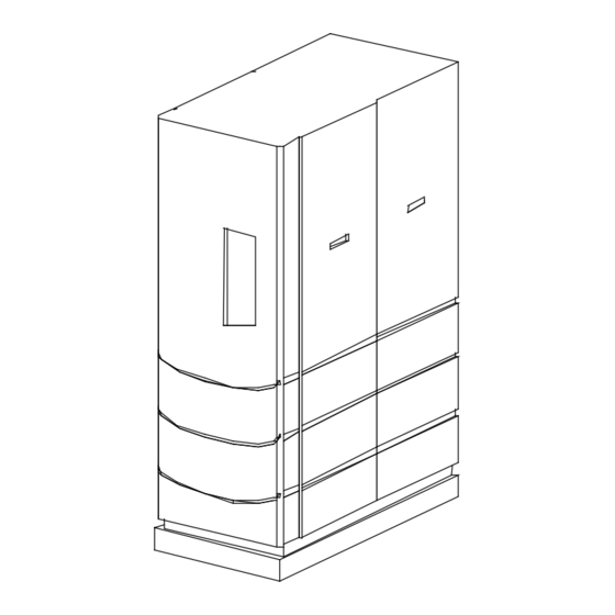
- Page 87 APPENDIX F BENCHMARK SHEET METAL ENCLOSURE PARTS LIST ITEM PART NO. DESCRIPTION FRONT PANEL ENCLOSURE 201113 201120 FRONT DOOR ASSEMBLY 161464 TOP RAIL 161463 TOP PANEL AERCO INTERNATIONAL, INC. SIDE PANEL ASSEMBLY NORTHVALE, NJ 07647 181144 RIGHT REAR PANEL 201126 BENCHMARK 2.0 LOW NOx BOILER PARTS LIST 201127...
- Page 88 APPENDIX G...
- Page 89 APPENDIX G...
- Page 90 APPENDIX G...
- Page 91 APPENDIX G...
- Page 92 APPENDIX G...
- Page 93 APPENDIX H...
- Page 94 APPENDIX H...
- Page 95 APPENDIX H...
- Page 96 APPENDIX H...
- Page 97 APPENDIX H...
- Page 98 APPENDIX H...
- Page 99 APPENDIX I RECOMMENDED PERIODIC TESTING CHECK LIST WARNING NOTE: Periodic testing of all boiler controls and safety devices is required to determine that they are operating as designed. Precautions shall be taken while tests are being performed to protect against bodily injury and property damage.
- Page 100 APPENDIX J CONNECTOR BOARD P/N 124366 LOW WATER CUTOFF BOARD P/N 124363 PMC BOARD P/N 124364 DISPLAY BOARD P/N 124365 GREEN LED P/N 124948 ENCLOSURE P/N 124951 ROCKER SWITCH P/N 124947 POWER SUPPLY BOARD V.F.D. DISPLAY P/N 124362 MODULE P/N 124527 IGNITION/STEPPER BOARD P/N 124361 FISH PAPER...
- Page 101 APPENDIX J INTERLOCK HARNESS CONNECTOR (16 PIN) TO INPUT/OUTPUT (I/O) SHELL HARNESS CONNECTOR (19 PIN) GAS TRAIN HARNESS CONNECTOR (9 PIN) A/F VALVE HARNESS CONNECTOR (16 PIN) EXT. SENSOR/COMM HARNESS CONNECTOR (24 PIN) TO INPUT/OUTPUT (I/O) SENSOR HARNESS CONNECTOR (7 PIN) BENCHMARK CONTROL PANEL REAR VIEW...
Need help?
Do you have a question about the AERCO Benchmark 2.0 LN and is the answer not in the manual?
Questions and answers