Table of Contents
Advertisement
Quick Links
Advertisement
Table of Contents

Subscribe to Our Youtube Channel
Related Manuals for Watts tekmar 289


Summary of Contents for Watts tekmar 289
- Page 1 IOM-T-289 Installation, Operation and Maintenance Manual Smart Boiler Control 289 Please read carefully before proceeding with installation. Your failure to follow any attached instructions or operating parameters may lead to the product’s failure. Keep this Manual for future reference.
-
Page 2: Table Of Contents
Table of Contents Important Safety Information . . . . . . . . . . . . . . . . . . . . . . . . . 3 Sequence of Operation . -
Page 3: Important Safety Information
Important Safety Information It is your responsibility to ensure that this control is safely • Improper installation and operation of this control could installed according to all applicable codes and standards . result in damage to the equipment and possibly even tekmar is not responsible for damages resulting from personal injury or death . -
Page 4: Radio Frequency Statement
Radio Frequency Statement This equipment has been tested and found to comply with the limits for a Class A digital device, pursuant to part 15 of the FCC Rules . These limits are designed to provide reasonable protection against harmful interference when the equipment is operated in a commercial environment . -
Page 5: Installation
Installation Installation Location When choosing the location for the control, consider the following: • Provide easy access for wiring, viewing, and adjusting the display screen . • Keep dry . Avoid potential leakage onto the control . RH ≤ 90% to 104°F (40°C) . •... -
Page 6: Wiring Schematic
Wiring Schematic This section provides a wiring schematic for the control . • Before wiring, ensure all power is turned off and take all • A circuit breaker or power disconnect that provides power necessary precautions . to the control should be located nearby and clearly labeled . •... -
Page 7: Wiring Instructions
Wiring Instructions This section explains how to wire individual devices to the Smart Steam Control 289 . Please refer to technical data table on pg 36 for sensors that are included in the standard packaging of the Smart Steam Control 289 . Pressure Sensor 089 (Terminals 1, 2, 3) An optional Pressure Sensor 089 (sold separately) can connect to the 289 to provide staging for a second steam boiler and to monitor steam pressure up to 15 psi (104 kPa) . - Page 8 • Connect 18 AWG or similar wire to the two terminals provided in the enclosure and run the wires from the sensor to the control . Do not run the wires parallel to telephone or power cables . If the sensor wires are located in an area with strong sources of electromagnetic interference (EMI), shielded cable or twisted pair should be used or the wires can be run in a grounded metal conduit .
-
Page 9: Testing The Sensor Wiring
Flue Sensor An optional Flue Sensor 069 can be installed on the boiler flue to measure the flue gas temperature . It is not possible to have both a flue sensor and an indoor sensor installed at the same time as they share the same auxiliary sensor input . - Page 10 DHW Call (Terminals 10, 11) If the DHW sensor option is not used, a call for indirect domestic hot water can come from an aquastat Ref In Gnd Outdoor Cond Class 2 Circuits Pressure Sens Sensor Sensor Sensor Call connected to terminals 10 and 11 . The DHW Call can be volt free or up to 24 V (ac) . •...
- Page 11 d'électrocution choc - ne pas CAN ICES-3 (A)/NMB-3(A) raccorder à un circuit fonctionnant à plus de 150 V à la terre. Combustion Air (C.A.) Damper (Terminals 17, 18) Smart Steam Control 289 Input Power: H2065A 115 V (ac) ±10%, 60 Hz, 4 W Relays: For product literature: 230 V (ac), 5 A, 1/3 hp...
-
Page 12: User Interface
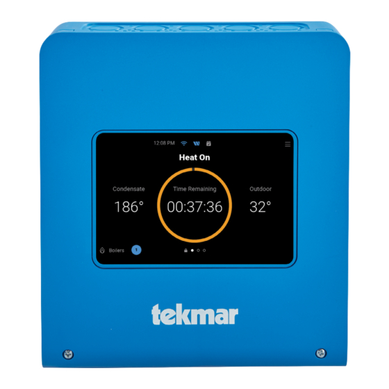
User Interface Power On • When first powered on, the tekmar logo appears . • If the display does not turn on, please contact your tekmar sales representative or technical support for assistance . Lock Screen • When first powered on, the tekmar logo appears followed by the lock screen . -
Page 13: Home Screen
When displayed, it indicates the sched- Blue indicates connection to Wi-Fi . ule is in the unoccupied period . WATTS ONSITE Blue indicates connection to the Watts ® Blue indicates that there is a domestic OnSite cloud service . hot water call . -
Page 14: System Inputs Screen
System Inputs Screen Heating Calls • The Room Target displays the desired room temperature when an indoor sensor is available . • Early Start is in effect when the dot is green . This is available when an indoor sensor is available . •... -
Page 15: Staging Status
Staging Status • The staging status is only available when the control is configured to operate two boilers . • The system pressure displays the pressure sensor reading . • The pressure target is the setpoint that the second steam boiler is shut off . •... -
Page 16: Reset Boiler Hours Or Cycles Screen
Reset Boiler Hours or Cycles Screen • Press check mark to zero the hours or cycle count . • Press X to cancel . Menu Screen Navigation BACK SKIP SKIP Go back a level without saving Skip step in Setup Wizard or Wi-Fi Setup HOME BEGIN BEGIN... -
Page 17: Menus
Menus Home Screen Parameter Range Description HOME SCREEN -32 to 266°F CONDENSATE The condensate return temperature . (-55 .0 to 65 .0°C) -67 to 149°F OUTDOOR The outdoor air temperature . (-35 .0 to 130°C) 100 to 220°F TARGET The condensate return must reach the steam established target to the Heat On cycle . (38 .0 to 104 .5 °C) 0 .0 to 15 .0 psi PRESSURE... -
Page 18: Settings (1 Of 5)
Parameter Range Description STAGING STATUS 0 .0 to 15 .0 psi SYSTEM The system steam pressure . (0 to 105 kPa) 1 .0 to 15 .0 psi TARGET The pressure that shuts off the second boiler . (0 to 105 kPa) 0 .1 to 5 .0 psi DIFFERENTIAL The pressure below the target to turn on the second boiler . -
Page 19: Settings (2 Of 5)
Enter the Wi-Fi password . Available when configuring a Wi-Fi network . WATTS ONSITE Register or Deregister Register the control with Watts OnSite to use the web or mobile apps . DHCP or Static Select if the control should receive an automatic IP address from the router DHCP CONFIGURATION server or use a static IP address . -
Page 20: Settings (3 Of 5)
Settings (3 of 5) Parameter Range Description HEATING CALLS > CENTRAL HEATING 35 to 100°F ROOM (2 .0 to 38 .0°C) Set the desired room air temperature during the occupied periods . OCCUPIED Default: 70°F (21 .0°C) 35 to 100°F ROOM Set the desired room air temperature during the unoccupied periods . -
Page 21: Settings (4 Of 5)
Settings (4 of 5) Parameter Range Description SYSTEM MENU Off or On CONDENSATE Select if a condensate return sensor is installed . SENSOR Default: On 100 to 220 °F STEAM (38 .0 to 104 .5 °C) Set the condensate return temperature at which steam reaches the furthest radiator . ESTABLISHED Default: 180 °F, (82 .0°C) Off or On... -
Page 22: Settings (5 Of 5)
Settings (5 of 5) Parameter Range Description ALERTS BOILER PLANT Off or On Select if an alert is triggered if the condensate return temperature does not increase . NO HEAT ALERT Requires a condensate sensor to be installed . Default: Off ENABLE Set the amount of time of no temperature change while boilers are firing after which 5 .0 to 80 .0 minutes... -
Page 23: Schedule Menu
Schedule Menu The control can follow an internal schedule to provide energy savings during unoccupied periods . When creating a new schedule, choose the days that share the same occupied and unoccupied time periods . Parameter Range Description 12:00 am to 12:50 pm OCCUPIED 1 (0:00 to 23:50) Set the occupied 1 time . -
Page 24: Notifications Menu
Notifications Menu The control keeps track of the last 30 errors and alert notifications . Refer to the Troubleshooting section for corrective action . Overrides Menu Parameter Range Description Set the manual override . Automatic reverts to normal operation . Automatic, Hand, OPERATION Hand allows each output to be turned on or set manually . -
Page 25: About Menu
About Menu The About menu lists all details about the control . This information may be required when contacting tekmar for support . Help Menu Scan the QR code with your mobile phone to be directed to the product website to find specifications, manuals, and videos . -
Page 26: Sequence Of Operation
Sequence of Operation Central Heating Operation The control operates either one or two steam boilers to heat a One Pipe System: Last Radiator building using an Outdoor Reset algorithm to progressively run the steam boiler longer when the outdoor air temperature is colder . - Page 27 Cycle Length When an indoor sensor is installed, the control has the option The Cycle Length determines the amount of time that the sys- to automatically change the cycle length to reduce ambient air tem repeats the heating cycle . The factory default is 60 min- temperature swing .
- Page 28 Room Occupied and Unoccupied The Room setting is the desired temperature of the building . - 100% C, D C, D When a programmable schedule is used, there are both Room A = Outdoor Start - 90% B = Boiler Start % Occupied and Room Unoccupied settings available .
-
Page 29: Time And Date
Cool Down To set the Cool Down Differential setting, it is recommended The Cool Down phase increases the efficiency of the system to start at 25°F (14 .0°C) and make adjustments up or down by allowing the latent heat of the steam remaining in the radi- based upon the system performance . -
Page 30: Schedule
Schedule Smart Setback Boost When the heating cycle reaches 85% on time, the Smart The boost feature is available when an indoor sensor is not Setback feature prevents the programmable schedule installed, and a programmable schedule is in use . Unoccupied period from going into effect to avoid long recovery When a programmable schedule is used to lower the times . -
Page 31: Domestic Hot Water Operation
Domestic Hot Water Operation The control is compatible with boilers with include a domestic hot water tankless coil . When the aquastat on the DHW tankless calls for heat, the control fires boiler 1 . Boiler 2 is not operated for DHW calls . -
Page 32: Troubleshooting
Troubleshooting It is recommended to complete all wiring to ensure trouble-free operation . Should an error occur, simply follow these steps: 1 . Find: If a banner is on the screen, it indicates a problem on the system . 2 . Identify: Press the BARS icon on the top right corner to enter the menus and press notifications . The latest error notification will appear at the top of the list . -
Page 33: Errors And Alerts (2 Of 3)
Errors and Alerts (2 of 3) Error or Alert Title Description An open circuit is detected with the indoor sensor on the Aux sensor input . The indoor sensor is optional, and the setting may be incorrectly turned on . Check if a sensor is installed . If not installed, set Auxiliary Sensor to off . -
Page 34: Errors And Alerts (3 Of 3)
2 . Check that the router firewall is not blocking or filtering MAC addresses 3 . Check that the router firewall is not blocking outbound port 23 The control is unable to connect to Watts OnSite . Please check that your router is not blocking outbound ports Watts OnSite Error 443 or 8883 . - Page 35 Notes _ _ _ _ _ _ _ _ _ _ _ _ _ _ _ _ _ _ _ _ _ _ _ _ _ _ _ _ _ _ _ _ _ _ _ _ _ _ _ _ _ _ _ _ _ _ _ _ _ _ _ _ _ _ _ _ _ _ _ _ _ _ _ _ _ _ _ _ _ _ _ _ _ _ _ _ _ _ _ _ _ _ _ _ _ _ _ _ _ _ _ _ _ _ _ _ _ _ _ _ _ _ _ _ _ _ _ _ _ _ _ _ _ _ _ _ _ _ _ _ _ _ _ _ _ _ _ _ _ _ _ _ _ _ _ _ _ _ _ _ _ _ _ _ _ _ _ _ _ _ _ _ _ _ _ _ _ _ _ _ _ _ _ _ _ _ _ _ _ _ _ _ _ _ _ _ _ _ _ _ _ _ _ _ _ _ _ _ _ _ _ _ _ _ _ _ _ _ _ _ _ _ _ _ _ _ _ _ _ _ _ _ _ _ _ _ _ _ _ _ _ _ _ _ _ _ _ _ _ _ _ _ _ _ _ _ _ _ _ _ _ _ _ _ _ _ _ _ _ _ _ _ _ _ _ _ _ _ _ _ _ _ _ _ _ _ _ _ _ _ _ _ _ _ _ _ _ _ _ _ _ _ _ _ _ _ _ _ _ _ _ _ _ _ _ _ _ _ _ _ _ _ _ _ _ _ _ _ _ _ _ _ _ _ _ _ _ _ _ _ _ _ _ _ _ _ _ _ _ _ _ _ _ _ _ _ _ _ _ _ _ _ _ _ _ _ _ _ _ _ _ _ _ _ _ _ _ _ _ _ _ _ _ _ _ _ _ _ _ _ _ _ _ _ _ _ _ _ _ _ _ _ _ _ _ _ _ _ _ _ _ _ _ _ _ _ _ _ _ _ _ _ _ _ _ _ _ _ _ _ _ _ _ _ _ _ _ _ _ _ _ _ _ _ _ _ _ _ _ _ _ _ _ _ _ _ _ _ _ _ _ _ _ _ _ _ _ _ _ _ _ _ _ _ _ _ _ _ _ _ _ _ _ _ _ _ _ _ _ _ _ _ _ _ _ _ _ _ _ _ _ _ _ _ _ _ _ _ _ _ _ _ _ _ _ _ _ _ _ _ _ _ _ _ _ _ _ _ _ _ _ _ _ _ _ _ _ _ _ _ _ _ _ _ _ _ _ _ _ _ _ _ _ _ _ _ _ _ _ _ _ _ _ _ _ _ _ _ _ _ _ _ _ _ _ _ _ _ _ _ _ _ _ _ _ _ _ _ _ _ _ _ _ _ _ _ _ _ _ _ _ _ _ _ _ _ _ _ _ _ _ _ _ _ _ _ _ _ _ _ _ _ _ _ _ _ _ _ _ _ _ _ _ _ _ _ _ _ _ _ _ _ _ _ _ _ _ _ _ _ _ _ _ _ _ _ _ _ _ _ _ _ _ _ _ _ _ _ _ _ _ _ _ _ _ _ _ _ _ _ _ _ _ _ _ _ _ _ _ _ _ _ _ _ _ _ _ _ _ _ _ _ _ _ _ _ _ _ _ _ _ _ _ _ _ _ _ _ _ _ _ _ _ _ _ _ _ _ _ _ _ _ _ _ _ _ _ _ _ _ _ _ _ _ _ _ _ _ _ _ _ _ _ _ _ _ _ _ _ _ _ _ _ _ _ _ _ _ _ _ _ _ _ _ _ _ _ _ _ _ _ _ _ _ _ _ _ _ _ _ _ _ _ _ _ _ _ _ _ _ _ _ _ _ _ _ _ _ _ _ _ _ _ _ _ _ _ _ _ _ _ _ _ _ _ _ _ _...
-
Page 36: Technical Data
Technical Data Smart Steam Control 289 Literature Submittal, Application, Installation and Operating Manual, Job Record, Watts OnSite Manual Packaged weight 3.3 lb. (1500 g) Dimensions 9" H x 8" W x 2 ⁄ " D (229 x 203 x 60 mm) Display 5"...
Need help?
Do you have a question about the tekmar 289 and is the answer not in the manual?
Questions and answers