Table of Contents
Advertisement
Quick Links
Advertisement
Table of Contents

Related Manuals for Watts AERCO Benchmark 2.0


Summary of Contents for Watts AERCO Benchmark 2.0
- Page 1 Benchmark 2.0 Gas-Fired Boiler GF-110 USER MANUAL OMM-0020_0A Applicable for Serial Numbers G-02-533 thru G-10-1060 Benchmark 2.0 Gas Fired Boiler System Condensing, Modulating Forced Draft, Hot Water Boiler 2,000,000 BTU/H Input Patent # : 2.155.12...
- Page 2 Benchmark 2.0 Gas-Fired Boiler GF-110 USER MANUAL OMM-0020_0A Telephone Support Direct to AERCO Technical Support (8 to 5 pm EST, Monday through Friday) (800) 526-0288 AERCO International, Inc. 100 Oritani Drive Blauvelt, NY 10913 www.aerco.com © AERCO International, Inc., 2009 The information contained in this operation and maintenance manual is subject to change without notice from AERCO International, Inc.
-
Page 3: Table Of Contents
CONTENTS GF-110 - THE AERCO BENCHMARK 2.0 GAS FIRED BOILER Operating & Maintenance Instructions FOREWORD Chapter 1 – SAFETY PRECAUTIONS Para. Subject Page Para. Subject Page Safety Warnings Prolonged Shutdown Emergency Shutdown Chapter 2 – INSTALLATION PROCEDURES Para. Subject Page Para. - Page 4 CONTENTS Chapter 5 – MODE OF OPERATION Para. Subject Page Para. Subject Page Introduction Boiler Management System Indoor/Outdoor Reset Mode (BMS) Constant Setpoint Mode Combination Control System Remote Setpoint Mode (CCS) Direct Drive Modes Chapter 6 – SAFETY DEVICE TESTING PROCEDURES Para.
- Page 5 CONTENTS APPENDICES Subject Page Subject Page Boiler Menu Item Descriptions Dimensional and Part Drawings Startup, Status and Fault Piping Drawings Messages Wiring Schematics Temperature Sensor Resistance Recommended Periodic Testing Chart Checklist Indoor/Outdoor Reset Ratio Benchmark Control Panel Views Charts Benchmark Dual-Fuel Propane Boiler Default Settings Switch-Over Instructions WARRANTIES...
- Page 6 FOREWORD Foreword The AERCO Benchmark boiler is a true industry advance that meets the needs of today's energy and environmental concerns. Designed for application in any closed loop hydronic system, the Benchmark's modulating capability relates energy input directly to fluctuating system loads.
- Page 7 SAFETY PRECAUTIONS CHAPTER 1 SAFETY PRECAUTIONS WARNING 1.1 WARNINGS & CAUTIONS DO NOT USE MATCHES, CANDLES, Installers and operating personnel MUST, at all FLAMES, OR OTHER SOURCES OF times, observe all safety regulations. The IGNITION TO CHECK FOR GAS following general warnings and cautions must be given the same attention as specific precautions LEAKS.
-
Page 8: Emergency Shutdown
SAFETY PRECAUTIONS 1.2 EMERGENCY SHUTDOWN If overheating occurs or the gas supply fails to shut off, close the manual gas shutoff valve (Figure 1-1) located external to the unit. IMPORTANT The Installer must identify and indicate MANUAL GAS SHUTOFF VALVE the location of the emergency shutdown manual gas valve to operating personnel. - Page 9 SAFETY PRECAUTIONS monoxide detectors. Extracted Information From 248 CMR 5.08 (2) – Continued a. In the event that the side wall horizontally vented gas fueled equipment is installed in a crawl space or an attic, the hard wired carbon monoxide detector with alarm and battery back-up may be installed on the next adjacent floor level.
- Page 10 1. The referenced "special venting system" instructions shall be included with the appliance or equipment installation instructions; and 2. The "special venting systems" shall be Product Approved by the Board, and the instructions for that system shall include a parts list and detailed installation instructions. (e) A copy of all installation instructions for all Product Approved side wall horizontally vented gas fueled equipment, all venting instructions, all parts lists for venting instructions, and/or all venting design instructions shall remain with the appliance or equipment at the completion of the installation.
-
Page 11: Receiving The Unit
INSTALLATION Chapter 2 - INSTALLATION 2.1 RECEIVING THE UNIT 2.2 UNPACKING Carefully unpack the unit taking care not to Each Benchmark is shipped as a single crated damage the unit jacket when cutting away unit. The shipping weight is approximately 1650 packaging materials. -
Page 12: Installation
INSTALLATION Lift the unit off the shipping skid and position it 2.3 INSTALLATION on to the 4 to 6 inch housekeeping concrete pad The unit must be installed with the prescribed (required) in the desired location. clearances for service as shown in Figure 2.1. The minimum clearance dimensions, required by In multiple unit installations, it is important to AERCO, are listed below. -
Page 13: Gas Supply Piping
INSTALLATION BOILER SUPPLY (4"-150# FLG'D CONN.) EXHAUST MANIFOLD 3/4" NPT CONDENSATE TRAP 1/2" NPT CONDENSATE DRAIN CONNECTION Figure 2.4 BOILER RETURN (4"-150# FLG'D CONN.) Condensate Drain Connection Location Figure 2.3 Supply and Return Location EXHAUST MANIFOLD 2.3.3 CONDENSATE DRAIN & PIPING The Benchmark Boiler is designed to condense water vapor from the flue products. - Page 14 INSTALLATION − Propane for Dual Fuel Unit: The maximum static pressure to the unit CAUTION! must be no more than 14” W.C. Minimum Many soaps used for gas pipe leak testing operating gas pressure for propane is 7.0” are corrosive to metals. The piping must be W.C.
-
Page 15: Electrical Supply
INSTALLATION TERMINAL BLOCK GAS SUPPLY: SEE GF-2030 FOR COMPLETE GAS PIPING INSTALLATION DETAILS NATURAL GAS SUPPLY PROPANE SUPPLY UPPER RIGHT CORNER OF FRONT PANEL FOR DUAL FUEL OPTION Figure 2.6 MANDATORY GAS AC Input Terminal Location DIRT PRESSURE REGULATORS TRAP (SUPPLIED BY AERCO) 2.5.1 ELECTRICAL REQUIREMENTS 2"... -
Page 16: Mode Of Operation And Field
INSTALLATION information on modes of operation, refer to Chapter 5. 220 VAC, 1 PHASE 208 VAC, 3 PHASE LOWER RIGHT CORNER OF FRONT PANEL 208 VAC, 3 Phase 220 VAC, 1 Phase 460 VAC, 3 PHASE TERMINAL STRIPS Figure 2.8 I/O Box Terminal Location 2.6.1 CONSTANT SETPOINT MODE 460 VAC, 3 Phase... - Page 17 INSTALLATION OUTDOOR SENSOR IN REMOTE INTL'K IN SENSOR COMMON AUX SENSOR IN EXHAUST SWITCH IN DELAYED INTL'K IN NOT USED NOT USED FAULT RELAY 120 VAC, 5A, RES ANALOG IN AUX RELAY 120 VAC, 5A, RES B.M.S. (PWM) IN NOT USED SHIELD RELAY CONTACTS: mA OUT...
- Page 18 INSTALLATION sensor must be shielded from direct sunlight as 2.6.5 COMBINATION MODE well as impingement by the elements. If a shield is used, it must allow for free air circulation. NOTE Only BMS Model 168 can be utilized for 2.7.2 AUX SENSOR IN the Combination Mode, not the BMS II The AUX SENSOR IN terminals can be used to (Model 5R5-384).
- Page 19 INSTALLATION This duty cycle is Pulse Width Modulated (PWM) The delayed interlock circuit (DELAYED INTL’K to control firing rate. A 0% firing rate = a 5% ON IN) is typically used in conjunction with the pulse and a 100% firing rate = a 95% ON pulse. auxiliary relay described in paragraph 2.8.
- Page 20 INSTALLATION The combined pressure drop of vent and The more common methods of supplying combustion air systems must not exceed 140 combustion air are outlined below. For more equivalent feet of 8 inch ducting. Fittings as well information concerning combustion air, consult as pipe lengths must be calculated as part of the the AERCO GF-2050, Venting and Combustion equivalent length.
-
Page 21: Introduction
CONTROL PANEL OPERATING PROCEDURES Chapter 3 - CONTROL PANEL OPERATING PROCEDURES 3.1. INTRODUCTION The information in this Chapter provides a guide to the operation of the Benchmark Boiler using the Control Panel mounted on the front of the unit. It is imperative that the initial startup of this unit be performed by factory trained personnel. - Page 22 CONTROL PANEL OPERATING PROCEDURES Table 3-1 Operating Controls, Indicators and Displays ITEM CONTROL, INDICATOR OR DISPLAY FUNCTION LED Status Indicators Four Status LEDs indicate the current operating status as follows: COMM Lights when RS-232 communication is occurring MANUAL Lights when the unit is being controlled using the front panel keypad.
- Page 23 CONTROL PANEL OPERATING PROCEDURES Table 3-1 Operating Controls, Indicators and Displays - Continued ITEM CONTROL, INDICATOR OR DISPLAY FUNCTION Menu Keypad Consists of 6 keys which provide the following functions for the Control Panel Menus: MENU Steps through the main menu categories shown in Figure 3-2.
-
Page 24: Control Panel Menus
CONTROL PANEL OPERATING PROCEDURES 3.3. CONTROL PANEL MENUS display options Bottom-Up sequence. The menu options will wrap The Control Panel incorporates an extensive around after the first or last available option menu structure which permits the operator to set is reached. up, and configure the unit. -
Page 25: Operating Menu
CONTROL PANEL OPERATING PROCEDURES 3.4. OPERATING MENU addition to permitting password entries, the Setup Menu is also used to enter date and time, The Operating Menu displays a number of key language to be used for display messages, units operating parameters for the unit as listed in of temperature measurements and entries Table 3-2. - Page 26 CONTROL PANEL OPERATING PROCEDURES 3.6. CONFIGURATION MENU NOTE: The Configuration Menu shown in Table 3-4 permits adjustment of the Internal Setpoint The Configuration Menu settings shown in Table (Setpt) temperature regardless of whether the 3-4 are Factory-Set in accordance with the valid password has been entered.
- Page 27 CONTROL PANEL OPERATING PROCEDURES 3.7. TUNING MENU these menu entries unless specifically requested to do so by Factory-Trained personnel. The Tuning Menu items in Table 3-5 are Factory set for each individual unit. Do not change Table 3-5. Tuning Menu Available Choices or Limits Menu Item Display Minimum...
- Page 28 CONTROL PANEL OPERATING PROCEDURES (a) Blower relay energizes and turns on blower. A/F VALVE (b) Air/Fuel Valve rotates to full-open purge position and closes purge position switch. The dial on the Air/Fuel Valve (Figure 3-4) will read 100 to indicate that it is full-open (100%).
- Page 29 CONTROL PANEL OPERATING PROCEDURES 8. With the unit firing properly, it will be Once the demand for heat has been satisfied, controlled by the temperature controller cir- the Control Box will turn off the gas valve. The cuitry. The FIRE RATE will be continuously blower relay will be deactivated and the Air/Fuel displayed on the front panel bargraph.
- Page 31 INITIAL START-UP Chapter 4 - INITIAL START- UP 4.1 INITIAL START- UP REQUIREMENTS TOOLS AND INSTRUMENTATION FOR COMBUSTION CALIBRATION The initial start-up of the Benchmark Boiler is comprised of the following steps: To properly perform combustion calibration, the proper instruments and tools must be used and •...
- Page 32 INITIAL START-UP 4.2.4 INSTALLING THE DIFFERENTIAL REGULATOR ADJUSTMENT TOOL FOR NATURAL GAS UNIT. 1. Remove the cap from the differential pressure regulator (see Figure 4.3). 2. Place the gasket from the regulator cap onto the regulator adjustment tool. 3. Prior to installing the tool on the regulator, pull up the screwdriver blade of the tool.
- Page 33 INITIAL START-UP 4. Engage the tool’s screwdriver blade into the regulator’s adjustment screw slot. NOTE: If calibrating a dual fuel unit, ensure that the diverter valve handle is set to the horizontal position for Natural Gas before proceeding. REGULATOR CAP 1.
- Page 34 INITIAL START-UP 15. If the measured oxygen reading is within the NOTE: specified range shown in Table 3, no further adjustment is necessary. Adjust only the differential regulator at 40% control signal. Do not adjust the iris air 16. If the measured oxygen level is not within damper.
- Page 35 INITIAL START-UP displayed, followed by the present rate in NOTE: %. Also, the MANUAL LED will light. Prior to calibrating a Dual-Fuel Unit for 8. Adjust the rate to 0% by pressing the ▼ propane, ensure that the Start and Stop arrow key.
- Page 36 INITIAL START-UP Table 5 insure that it is still within the range specified in Table 4. Combustion Oxygen Levels for a 24% Firing Rate 19. Continue this procedure until oxygen levels Inlet Air Carbon at 40%, 24% and 100% firing rates are Oxygen Temp Monoxide...
- Page 37 INITIAL START-UP 4.6 OVER-TEMPERATURE LIMIT SWITCH The over-temperature limit switches are located on the plate to the left of the boiler shell. One is a fixed manual reset switch that will shutdown and lock out the boiler if the water temperature reaches 210°F.
- Page 39 MODE OF OPERATION CHAPTER 5 MODE OF OPERATION 5.1 INTRODUCTION 5.2.3 Outdoor Air Temperature Sensor Installation The Benchmark Boiler is capable of being operated in any one of six different modes. The The outdoor air temperature sensor must be following paragraphs in this Chapter provide mounted on the North side of the building in an descriptions of each of these operating modes.
- Page 40 MODE OF OPERATION 5.4 REMOTE SETPOINT MODES 7. Press the CHANGE key. The display will The unit’s setpoint can be remotely controlled by begin to flash. an Energy Management System (EMS) or 8. Use the ▲ and ▼ arrow keys to select the Building Automation System (BAS).
- Page 41 MODE OF OPERATION If the Network setting is selected for RS485 5.5 DIRECT DRIVE MODES Modbus operation, a valid Comm Address must The unit’s fire rate can be changed by a remote be entered in the Setup Menu. Refer to Modbus signal which is typically sent from an Energy Communication Manual GF-114 for additional Management System (EMS) or from a Building...
- Page 42 MODE OF OPERATION If the Network setting is selected for RS485 Guide. For operation via an RS485 Modbus Modbus operation, a valid Comm Address must network, refer to the Modbus Communication be entered in the Setup Menu. Refer to Modbus Manual GF-114.
- Page 43 MODE OF OPERATION 5.7 COMBINATION CONTROL SYSTEM 5.7.1 Combination Control System Field (CCS) Wiring NOTE Wiring for this system is between the BMS Model 168 panel, the CCP and the B.M.S. Only BMS Model 168 can be utilized for (PWM) IN terminals in the I/O Box. Wire the the Combination Mode, not the BMS II units using a shielded twisted pair of 18 to 22 (Model 5R5-384).
- Page 45 SAFETY DEVICE TESTING Chapter 6 SAFETY DEVICE TESTING PROCEDURES 6.1 TESTING OF SAFETY DEVICES 6. While the unit is firing, slowly close the Manual gas shut-off valve located down- Periodic safety device testing is required to stream of the gas supply regulator. The unit ensure that the control system and safety should shut...
- Page 46 SAFETY DEVICE TESTING 4. Reconnect the wire previously removed from the high gas pressure switch and depress the CLEAR button. ADJUSTABLE TEMPERATURE LIMIT SWITCH 5. The unit should restart. 6.4 LOW WATER LEVEL FAULT TEST 1. Place the ON/OFF switch in the OFF position.
- Page 47 SAFETY DEVICE TESTING 6.6.1 REMOTE INTERLOCK 6.7 FLAME FAULT TEST 1. Remove the cover from the I/O Box and locate the REMOTE INTL’K IN terminals. 1. Place the ON/OFF switch in the OFF position. 2. Start the unit in manual mode and fire at 25% to 30% firing rate.
- Page 48 SAFETY DEVICE TESTING NATURAL GAS A/F VALVE POSITION CLOSED TO FRAME POSITION HARNESS Figure 6.5 Blower Proof Switch Location and Wiring Figure 6.4 Diverter Valve Positions 6.9 SSOV PROOF OF CLOSURE SWITCH 1. Set the unit’s ON/OFF switch to the OFF position.
- Page 49 SAFETY DEVICE TESTING 5. Replace the wire on the ignition position switch and depress the CLEAR button. The unit should restart. SSOV ACTUATOR COVER VALVE COVER COVER SCREW Figure 6.6 SSOV Actuator Cover Screw Location 6.10 PURGE SWITCH OPEN DURING PURGE Figure 6.7 1.
- Page 51 MAINTENANCE Chapter 7 - MAINTENANCE BURNER 7.1 MAINTENANCE SCHEDULE The unit requires regular routine maintenance to keep up efficiency and reliability. For best operation and life of the unit, the following routine maintenance procedures should be carried out in the time periods specified in Table 7-1.
-
Page 52: Combustion Air
MAINTENANCE bushing over the contactor and reconnect 8. Reinstall the side and top panels on the unit. the igniter cable. Table 7-1 - Maintenance Schedule Labor PARAGRAPH ITEM 6 Mos. 12 Mos. 24 Mos. Time Spark Igniter *Inspect Replace 15 mins. (GP-122435-S) Flame Detector *Inspect... - Page 53 MAINTENANCE 7.5 SAFETY DEVICE TESTING 5/16–16 HOSE BOLTS (6) CLAMP Systematic and thorough tests of the operating BURNER and safety devices should be performed to ensure that they are operating as designed. Certain code requirements, such as ASME CSD-1, require that these tests be performed on a scheduled basis.
- Page 54 MAINTENANCE train realignment is required, loosen the 7.7 CONDENSATE DRAIN TRAP support brackets/U-bolts at the upper and The boiler contains a condensate drain trap lower portions of the gas train as shown in connected to the drain line of the exhaust Figure 7.4.
- Page 55 MAINTENANCE 7.8 SHUTTING THE BOILER DOWN FOR AN EXTENDED PERIOD OF TIME If the boiler is to be taken out of service for an extended period of time, one year or more, the following instructions must be followed: 1. Set ON/OFF switch on the front panel to the OFF position to shut down the boiler’s operating control.
- Page 57 TROUBLESHOOTING Chapter 8- TROUBLESHOOTING GUIDE 2. Refer to the Fault Indication column in the 8.1 INTRODUCTION following troubleshooting tables and locate This troubleshooting guide is intended to aid the Fault that best describes the existing service/maintenance personnel in isolating the conditions.
- Page 66 APPENDIX C Temperature Sensor Resistance Chart (Balco)
- Page 67 APPENDIX D INDOOR/OUTDOOR RESET RATIO CHARTS Header Temperature for a Building Reference Temperature of 50F RESET RATIO Temp -10F -15F -20F Header Temperature for a Building Reference Temperatrure of 60F RESET RATIO Temp -10F -15F -20F...
- Page 68 APPENDIX D Header Temperature for a Building Reference Temperature of 65F RESET RATIO Temp Header Temperature for a Building Reference Temperature of 70F RESET RATIO Temp -10F -15F -20F...
- Page 69 APPENDIX D Header Temperature for a Building Reference Temperature of 75F RESET RATIO Temp -10F -15F Header Temperature for a Building Reference Temperature of 80F RESET RATIO Temp -10F...
- Page 70 APPENDIX D Header Temperature for a Building Reference Temperature of 90F RESET RATIO Temp...
-
Page 71: Configuration Menu
APPENDIX E BOILER DEFAULT SETTINGS MENU & OPTION FACTORY DEFAULT Setup Menu Password Language English Unit of Temp Fahrenheit Comm Address Baud Rate 9600 Configuration Menu Internal Setpt 130°F Unit Type Boiler Unit Size 1.0 MBTU Boiler Mode Constant Setpoint Remote Signal 4 –... - Page 72 APPENDIX F BLOWER DESCRIPTION ITEM PART NO. 27003-1 COMBUSTION AIR BLOWER (1 PHASE) 27003-3 COMBUSTION AIR BLOWER (3 PHASE) 99008-5 5" IRIS AIR DAMPER 123585 A/F VA. INLET HOSE 96003 INCREASER, 5" TO 6" 123681 8" INLET ADAPTOR (SEE NOTE 5) 96004-2 POLY BLOWER INLET DUCT 123990...
- Page 73 APPENDIX F 32 31 SEE VIEW A-A (OPPOSITE SIDE OF TRANSFORMER) VIEW A-A AERCO INTERNATIONAL, INC. NORTHVALE, NJ 07647 BENCHMARK 2.0 BOILER PARTS LIST DWN.BY DATE 041304 PL-A-140 SCALE (SH. 2 OF 3) APPD. DATE...
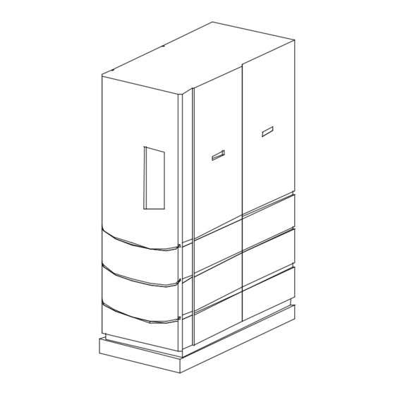
- Page 74 APPENDIX F BENCHMARK SHEET METAL ENCLOSURE PARTS LIST ITEM PART NO. DESCRIPTION FRONT PANEL ENCLOSURE 201113 201120 FRONT DOOR ASSEMBLY 161464 TOP RAIL 161463 TOP PANEL AERCO INTERNATIONAL, INC. SIDE PANEL ASSEMBLY 181144 NORTHVALE, NJ 07647 201126 RIGHT REAR PANEL BENCHMARK 2.0 BOILER PARTS LIST LEFT REAR PANEL...
- Page 75 APPENDIX F...
- Page 76 APPENDIX F...
- Page 77 APPENDIX F...
- Page 78 APPENDIX F...
- Page 79 APPENDIX F...
- Page 80 APPENDIX F...
- Page 81 APPENDIX F F-10...
- Page 82 APPENDIX G...
- Page 83 APPENDIX G...
- Page 84 APPENDIX G...
- Page 85 APPENDIX G...
- Page 86 APPENDIX G...
- Page 87 APPENDIX H...
- Page 88 APPENDIX H...
- Page 89 APPENDIX H...
- Page 90 APPENDIX H...
- Page 91 APPENDIX H...
- Page 92 APPENDIX H...
- Page 93 APPENDIX I RECOMMENDED PERIODIC TESTING CHECK LIST WARNING NOTE: Periodic testing of all boiler controls and safety devices is required to determine that they are operating as designed. Precautions shall be taken while tests are being performed to protect against bodily injury and property damage.
- Page 94 APPENDIX J CONNECTOR BOARD P/N 124366 LOW WATER CUTOFF BOARD P/N 124363 PMC BOARD P/N 124364 DISPLAY BOARD P/N 124365 GREEN LED P/N 124948 ENCLOSURE P/N 124951 ROCKER SWITCH P/N 124947 POWER SUPPLY BOARD V.F.D. DISPLAY P/N 124362 MODULE P/N 124527 IGNITION/STEPPER BOARD P/N 124361 FISH PAPER...
- Page 95 APPENDIX J INTERLOCK HARNESS CONNECTOR (16 PIN) TO INPUT/OUTPUT (I/O) SHELL HARNESS CONNECTOR (19 PIN) GAS TRAIN HARNESS CONNECTOR (9 PIN) A/F VALVE HARNESS CONNECTOR (16 PIN) EXT. SENSOR/COMM HARNESS CONNECTOR (24 PIN) TO INPUT/OUTPUT (I/O) SENSOR HARNESS CONNECTOR (7 PIN) BENCHMARK CONTROL PANEL REAR VIEW...
- Page 96 APPENDIX K BENCHMARK DUAL-FUEL PROPANE SWITCH-OVER INSTRUCTIONS Prior to operating a Benchmark Dual-Fuel Unit using propane, the Start and Stop levels must be changed to 28% and 24%. In addition, the following valves must be set to the following positions: •...
- Page 97 APPENDIX K DIVERTER VALVE HANDLE PROPANE POSITION DIVERTER VALVE HANDLE NATURAL GAS POSITION NAT. GAS DIVERTER VALVE HANDLE CLOSED POSITION FUEL IN FIGURE 1. DUAL-FUEL DIVERTER VALVE DUAL FUEL BENCHMARK BURNER INJECTION TUBE OPEN POSITION (HANDLE IN LINE WITH TUBE) AIR INJECTION VALVE PARTIAL TOP VIEW SHOWING DUAL FUEL BURNER...
Need help?
Do you have a question about the AERCO Benchmark 2.0 and is the answer not in the manual?
Questions and answers