Table of Contents
Advertisement
Quick Links
EB 8222-1 EN
Translation of original instructions
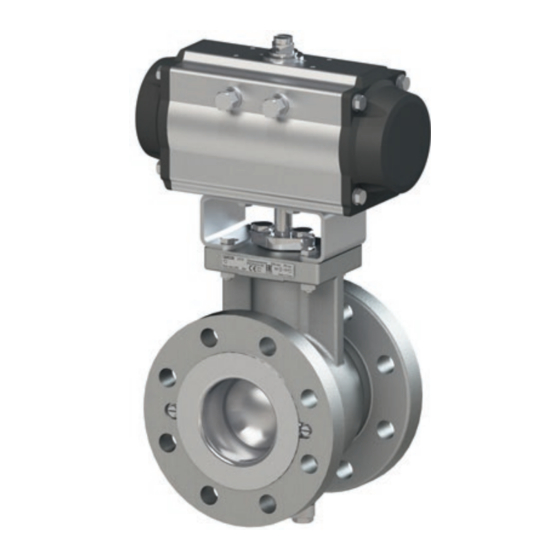
Cutaway view of Type 3310 Segmented Ball
Type 3310 Segmented Ball Valve with
Valve with AIR TORQUE Type SRP/DAP
AIR TORQUE Type SRP/DAP Actuator
Actuator and positioner
Type 3310 Segmented Ball Valve · Updated edition 2020
In combination with an actuator,
e.g. AIR TORQUE Type SRP/DAP Pneumatic Rotary Actuator or
SAMSON Type 3278 Pneumatic Rotary Actuator
Edition June 2020
Advertisement
Table of Contents

Subscribe to Our Youtube Channel
Related Manuals for Samson 3310


Summary of Contents for Samson 3310
- Page 1 Type 3310 Segmented Ball Valve with Valve with AIR TORQUE Type SRP/DAP AIR TORQUE Type SRP/DAP Actuator Actuator and positioner Type 3310 Segmented Ball Valve · Updated edition 2020 In combination with an actuator, e.g. AIR TORQUE Type SRP/DAP Pneumatic Rotary Actuator or SAMSON Type 3278 Pneumatic Rotary Actuator...
- Page 2 Note on these mounting and operating instructions These mounting and operating instructions assist you in mounting and operating the device safely. The instructions are binding for handling SAMSON devices. The images shown in these instructions are for illustration purposes only. The actual product may vary.
-
Page 3: Table Of Contents
Contents Safety instructions and measures ..............1-1 Notes on possible severe personal injury ............1-4 Notes on possible personal injury ..............1-4 Notes on possible property damage .............1-6 Warnings on the device ................1-7 Markings on the device ................2-1 Valve nameplate ..................2-1 Actuator nameplate ..................2-2 Material numbers ..................2-2 Marking to indicate direction of flow ............2-2 Design and principle of operation ...............3-1... - Page 4 Removal ....................11-1 11.1 Removing the valve from the pipeline ............11-2 11.2 Removing the actuator from the valve ............11-2 Repairs ....................12-1 12.1 Returning devices to SAMSON ..............12-1 Disposal ....................13-1 Certificates ....................14-1 Annex......................15-1 15.1 Tightening torques, lubricants and tools ............15-1 15.2 Accessories ....................15-1 15.3...
-
Page 5: Safety Instructions And Measures
In case operators intend to use the control valve in other applications or conditions than specified, contact SAMSON. SAMSON does not assume any liability for damage resulting from the failure to use the de- vice for its intended purpose or for damage caused by external forces or any other external factors. - Page 6 Î Check with the plant operator for details on further protective equipment. Revisions and other modifications Revisions, conversions or other modifications of the product are not authorized by SAMSON. They are performed at the user's own risk and may lead to safety hazards, for example. Fur- thermore, the product may no longer meet the requirements for its intended use.
- Page 7 Start-up and shutdown procedures fall within the scope of the operator's duties and, as such, are not part of these mounting and operating instructions. SAMSON is unable to make any statements about these procedures since the operative details (e.g. differential pressures and temperatures) vary in each individual case and are only known to the operator.
-
Page 8: Notes On Possible Severe Personal Injury
The following documents apply in addition to these mounting and operating instructions: − Mounting and operating instructions for the mounted actuator, e.g. u EB 8321 for the SAMSON Type 3278 Pneumatic Rotary Actuator − Mounting and operating instructions for mounted valve accessories (positioner, solenoid valve etc.) - Page 9 Safety instructions and measures WARNING Risk of hearing loss or deafness due to loud noise. The noise emissions depend on the valve version, plant facilities and process medium. Î Wear hearing protection when working near the valve. Risk of personal injury due to exhaust air being vented from pneumatically operated components.
-
Page 10: Notes On Possible Property Damage
Safety instructions and measures WARNING Risk of personal injury due to residual process medium in the valve. While working on the valve, residual medium can flow out of the valve and, depending on its properties, cause personal injury, e.g. (chemical) burns. Î... -
Page 11: Warnings On The Device
Risk of valve damage due to the use of unsuitable tools. Certain tools are required to work on the valve. Î Only use tools approved by SAMSON (u AB 0100). Risk of valve damage due to the use of unsuitable lubricants. The lubricants to be used depend on the valve material. Unsuitable lubricants may cor- rode and damage surfaces. - Page 12 Safety instructions and measures EB 8222-1 EN...
-
Page 13: Markings On The Device
Markings on the device 2 Markings on the device 2.1 Valve nameplate 3310 90° 70° Made in France Fig. 2-1: Inscriptions on the valve nameplate Item Inscription meaning Item Inscription meaning Manufacturer PED: Pressure Equipment Directive Type designation Notified body (PED) Serial no.:... -
Page 14: Actuator Nameplate
Markings on the device 2.4 Marking to indicate direc- The nameplate is affixed to the valve body (see Fig. 2-2). tion of flow The standard direction flow is indicated by an arrow stamped on the side of the valve body. When the reverse direction of flow is used, a mounted label indicates the changed direction of flow. -
Page 15: Design And Principle Of Operation
(5). The actuator motion is trans- ation mitted to the segmented ball valve by the The Type 3310 Valve is a segmented ball valve shaft (12) with square or key drive. The valve. This valve is preferably to be com- valve shaft (12) is sealed by a packing (40). - Page 16 Design and principle of operation Stop bolt A Stop bolt B 70/80 Valve seat Fig. 3-1: Sectional view of Type 3310 Valve · Standard version with AIR TORQUE Type SRP/DAP Ac- tuator EB 8222-1 EN...
- Page 17 Design and principle of operation Stop bolt 2 Stop bolt 1 70/80 Valve seat Fig. 3-2: Sectional view of Type 3310 Valve · Version with standard insulating section and SAMSON Type 3278 Actuator EB 8222-1 EN...
-
Page 18: Double-Acting Type Dap Pneumatic Rotary Actuator
Actuator (see Information Sheet u T 8350). Mounting The double-acting AIR TORQUE Type DAP parts are available for SAMSON valve ac- Rotary Actuator is not fitted with springs. A cessories. See actuator documentation. defined final position is not reached when the supply air fails. -
Page 19: Technical Data
Note More information is available in Data Sheet u T 8222-1. Noise emissions SAMSON is unable to make general state- ments about noise emissions. The noise emis- sions depend on the valve version, plant fa- cilities and process medium. EB 8222-1 EN... - Page 20 Design and principle of operation Table 3-1: Technical data for Type 3310 Valve Soft seal Metal seal Type Valve seat Version PTFE PEEK ARCAP Enhanced ® 1.4404/316L Material PTFE PEEK AP1C and Stellite ® PN 10 · 16 · 25 · 40 Pressure rating Class 150/300...
- Page 21 Design and principle of operation Dimensions and weights Dimensions in mm · Weights in kg Table 3-2: Dimensions for Type 3310 Valve 1½ Valve 100 150 200 250 300 Standard – Form B1 – Raised face (DIN) DEM – Form C – Tongue (DIN) DEF –...
- Page 22 Standard version of Type 3310 Valve Ø J Type 3310 Valve with standard insulating section Note For more dimensions and weights refer to the Data Sheet u T 8222-1. The associated actuator documentation applies to actuators, e.g.: u T 8321 for the SAMSON Type 3278 Pneumatic Rotary Actuator EB 8222-1 EN...
-
Page 23: Shipment And On-Site Transport
Shipment and on-site transport 4 Shipment and on-site trans- Î Leave the control valve in its transport container or on the pallet to transport it port on site. The work described in this section is only to Î Do not remove the protective caps from be performed by personnel appropriately the inlet and outlet until immediately be- qualified to carry out such tasks. -
Page 24: Transporting The Valve
Shipment and on-site transport WARNING Risk of personal injury due to the control valve tipping over. Î Observe the valve's center of gravity. Î Secure the valve against tipping over or turning. WARNING Risk of injury due to incorrect lifting without the use of lifting equipment. -
Page 25: Lifting The Valve
Shipment and on-site transport − The permissible transportation tempera- hook) of the crane or forklift (see ture of standard control valves is –20 to Fig. 4-1). +65 °C (–4 to +149 °F). 2. If necessary, attach additional slings that do not bear any load but prevent the Note control valve from turning or tipping Contact our after-sales service for the trans-... -
Page 26: Storing The Valve
Î Observe the storage instructions. vent cracking, do not bend them or hang Î Avoid long storage times. them up. Î Contact SAMSON in case of different − We recommend a storage temperature of storage conditions or long storage peri- 15 °C (59 °F) for elastomers. -
Page 27: Installation
Installation 5 Installation 5.1 Installation conditions The work described in this section is only to Work position be performed by personnel appropriately The work position for the control valve is the qualified to carry out such tasks. front view looking onto the operating con- trols (including valve accessories). -
Page 28: Preparation For Installation
Installation 5.2 Preparation for installation Î Contact SAMSON if the mounting posi- tion is not as specified above. Before installation, make sure the following Support or suspension conditions are met: − The valve is clean. Note − The valve and all valve accessories (in- The plant engineering company is responsi- cluding piping) are not damaged. - Page 29 Installation Î When the valve and actuator are al- ready assembled, check the tightening torques of the bolted joints (u AB 0100). Components may loosen during trans- port. Legend for Fig. 5-1 and Fig. 5-2 Support shaft Valve shaft Gasket Yoke Packing gland Spacer Bottom flange Bearing bushing Retaining screw Insulating section Bearing bushing...
- Page 30 Installation Stop bolt A Stop bolt B 70/80 Valve seat Fig. 5-1: Sectional view of Type 3310 Valve · Standard version with AIR TORQUE Type SRP/DAP Actuator EB 8222-1 EN...
- Page 31 Installation Stop bolt 2 Stop bolt 1 70/80 Valve seat Fig. 5-2: Sectional view of Type 3310 Valve · Version with standard insulating section and SAMSON Type 3278 Actuator EB 8222-1 EN...
-
Page 32: Installing The Device
Risk of valve damage due to the use of un- spring force suitable tools. Fail-close Clockwise Î Only use tools approved by SAMSON Fail-open Counterclockwise (u AB 0100). The square drive allows the actuator to be 5.3.1... - Page 33 Installation 3. If necessary, place the shaft adapter on screws. There must be no clearance be- the valve shaft (12). Slide the actuator tween the actuator and valve shaft (12)/ over the adapter or valve shaft (12) and shaft adapter. If necessary, insert thin fasten it onto the yoke (2) with four wedges (see Fig. 5-3 and the 'Accesso- screws.
- Page 34 Installation b) Type 3310 Valve with 4. Slide the actuator over the valve shaft (12) and fasten it onto the yoke (2) with Type 3278 Actuator four screws. Mount the actuator onto the body flange 1 5. Undo the stop bolt 2 again. or 2 depending on the characteristic and 6.
-
Page 35: Installing The Valve Into The Pipeline
Installation the loading pressure connection to close flow causes the pressure of the process the valve. medium to constantly act on the packing. On tightening the flange bolts, make sure 7. Adjust the stop bolt 1 to the point where that an even pressure is exerted on the the segmented ball (7) completely closes gaskets. -
Page 36: Signal Pressure Connection
Installation 5.3.3 Signal pressure connec- cessories not fitted with noise-reducing fit- tings. Both can damage hearing. tion Î Wear hearing protection when working Î Connect the signal pressure to the signal near the valve. pressure connection on the pneumatic actuator as described in the actuator WARNING WARNING documentation. -
Page 37: Leak Test
Installation To test the valve functioning before start-up Î Apply the maximum and minimum con- or putting back the valve into operation, per- trol signals to check the end positions of form the following tests: the valve while observing the movement of the valve shaft. - Page 38 5-12 EB 8222-1 EN...
-
Page 39: Start-Up
Start-up 6 Start-up WARNING WARNING The work described in this section is only to Risk of personal injury due to exhaust air be performed by personnel appropriately being vented from pneumatically operated qualified to carry out such tasks. components. While the valve is operating, the actuator, for example, may vent during closed-loop WARNING operation or when the valve opens or closes. - Page 40 Start-up Start-up/putting the device back into oper- ation 1. Allow the valve to cool down or warm up to reach ambient temperature before start-up when the ambient temperature and process medium temperature differ greatly or the medium properties require such a measure. 2.
-
Page 41: Operation
Operation 7 Operation WARNING WARNING Immediately after completing start-up or put- Risk of personal injury due to exhaust air ting the valve back into operation, the valve being vented from pneumatically operated is ready for use. components. While the valve is operating, the actuator, for example, may vent during closed-loop WARNING operation or when the valve opens or closes. - Page 42 EB 8222-1 EN...
-
Page 43: Malfunctions
Malfunctions 8 Malfunctions Read hazard statements, warnings and caution notes in the 'Safety instructions and mea- sures' section. 8.1 Troubleshooting Malfunction Possible reasons Recommended action Valve shaft does Initial breakaway torque Shut off the section of the pipeline and flush the not move on de- too high valve to remove any deposits (dirt or other foreign... - Page 44 Malfunctions Malfunction Possible reasons Recommended action Increased flow Dirt or other foreign parti- Shut off the section of the pipeline and flush the through closed cle deposits have collected valve. valve (seat leak- inside the valve. Depressurize valve and actuator. Use a cloth to age).
-
Page 45: Emergency Action
Malfunctions Note Contact our after-sales service for malfunc- tions not listed in the table. 8.2 Emergency action The plant operator is responsible for emer- gency action to be taken in the plant. In the event of a valve malfunction: 1. Close the shut-off valves upstream and downstream of the control valve to stop the process medium from flowing through the valve. - Page 46 EB 8222-1 EN...
-
Page 47: Service And Conversion Work
− Mounting and operating instructions for Risk of hearing loss or deafness due to loud the mounted actuator, e.g. u EB 8321 noise. for the SAMSON Type 3278 Pneumatic Noise emission (e.g. cavitation or flashing) Rotary Actuator may occur during operation caused by the −... - Page 48 NOTICE Risk of valve damage due to the use of unsuitable tools. WARNING Î Only use tools approved by SAMSON Risk of personal injury due to preloaded (u AB 0100). springs. Actuators with preloaded springs are under tension.
-
Page 49: Periodic Testing
Service and conversion work 2. Put the control valve out of operation (see Note the 'Decommissioning' section). The control valve was checked by SAMSON 3. Remove the actuator from the valve. See before it left the factory. associated actuator documentation. -
Page 50: Conversion Work
Type 3278 Pneumatic Rotary torques. Actuator 9.4.2 Changing the character- The fail-safe action of SAMSON Type 3278 istic Actuator can be changed from fail-close to fail-open or vice versa after the valve has Changing the characteristic from equal per- been installed. In this case, the side where... -
Page 51: Service Work
Service and conversion work 9.5 Service work (15) and insert the bearing bushing (17) from below into the packing gland. Î Before performing any service work, 3. Pull the entire packing parts (35, 40, 20, preparations must be made to the control 10, 24, 49) out of the packing chamber valve (see section 9.2). -
Page 52: Replacing The Seat Ring
Service and conversion work 10. Push the packing (40) into the packing Preparation work for all versions chamber. Make sure the V-rings are 1. Unscrew both retaining screws (70) and properly aligned (see Fig. 9-3). remove them together with the washers 11. - Page 53 Service and conversion work a) Soft-seated PTFE version (S) 7. Insert the retainer (30) with gasket (46) into the valve body and fasten using re- See Fig. 9-5 taining screws (70) and washers (80). Observe tightening torques. 1. Remove the support ring (25) and seat ring (21).
- Page 54 Service and conversion work b) Soft-seated PEEK version (S) 5. Insert the support ring (25). Make sure it is properly aligned (see Fig. 9-6). See Fig. 9-6 6. Mount the gasket (46) onto the retainer 1. Remove the support ring (25) and seat (30).
- Page 55 Service and conversion work c) ARCAP metal-seated version page 9-7) and fasten using retaining ® screws (70) and washers (80). Observe tightening torques. See Fig. 9-7 1. Remove in sequence any washer(s) (23), metal tubular seal (26) and seat ring (21). 2. Check the marking on the packing gland (15) for the distribution of washers (23).
- Page 56 Service and conversion work 23 Position A 23 Position B Fig. 9-7: ARCAP metal-seated version (A) ® 9-10 EB 8222-1 EN...
- Page 57 Service and conversion work d) Enhanced metal-seated 4. Insert the spring-loaded gasket (27) into the retainer (30). version (E) 5. Insert the new seat ring (21) into the re- See Fig. 9-8 tainer (30). 1. Remove the seat ring (21) und 6.
-
Page 58: Replacing The Segmented Ball, Valve Shaft And Bearings
Î If the initial breakaway torque required Contact your nearest SAMSON subsidiary to open the valve is too high, the wash- or SAMSON's After-sales Service for infor- ers (23) in position B (between the metal mation on spare parts, lubricants and tools. -
Page 59: Decommissioning
Decommissioning 10 Decommissioning WARNING The work described in this section is only to Risk of hearing loss or deafness due to loud be performed by personnel appropriately noise. qualified to carry out such tasks. Noise emission (e.g. cavitation or flashing) may occur during operation caused by the process medium and the operating condi- DANGER... - Page 60 Decommissioning Î Before attempting to unblock a segment- To decommission the control valve for service ed ball after it has become blocked (e.g. work or to remove it from the pipeline, pro- due to seizing up after remaining in the ceed as follows: same position for a long time), release 1.
-
Page 61: Removal
Removal 11 Removal Î Do not impede the rotary motion of the segmented ball by inserting objects into The work described in this section is only to its path. be performed by personnel appropriately Î Before attempting to unblock a segment- qualified to carry out such tasks. -
Page 62: Removing The Valve From The Pipeline
Removal 11.1 Removing the valve from the pipeline 1. Support the valve to hold it in place when separated from the pipeline (see the 'Shipment and on-site transport' sec- tion). 2. Unbolt the flange joint. 3. Remove the valve from the pipeline (see the 'Shipment and on-site transport' sec- tion). -
Page 63: Repairs
Î Do not perform any repair work on your outside of your shipment so that the own. documents are clearly visible. Î Contact SAMSON's After-sales Service 4. Send the shipment to the address given for repair work. on the RMA. - Page 64 12-2 EB 8222-1 EN...
-
Page 65: Disposal
Disposal 13 Disposal Î Observe local, national and internation- al refuse regulations. Î Do not dispose of components, lubricants and hazardous substances together with your household waste. EB 8222-1 EN 13-1... - Page 66 13-2 EB 8222-1 EN...
-
Page 67: Certificates
Certificates 14 Certificates The following declarations are included on The following declarations only apply to the next pages: valves that have been specifically ordered to meet such requirements. − Declaration of conformity in compliance with Pressure Equipment Directive − Declaration of conformity for valve with 2014/68/EU on pages 14-2 to 14-3 gaskets and packings that comply with the EU Regulation (EC) No. 1935/2004... - Page 68 BNP Paribas N° compte 0002200215245 • Banque 3000401857 Tél.: +33 (0)4 72 04 75 00 • Fax: +33 (0)4 72 04 75 75 • E-mail: samson@samson.fr • Internet: www.samson.fr IBAN FR7630004018570002200215245 • BIC (code SWIFT) BNPAFRPPVBE Société par actions simpifiée au capital de 10 000 000 € • Siège social : Vaulx-en-Velin Crédit Lyonnais...
- Page 69 BNP Paribas N° compte 0002200215245 • Banque 3000401857 Tél.: +33 (0)4 72 04 75 00 • Fax: +33 (0)4 72 04 75 75 • E-mail: samson@samson.fr • Internet: www.samson.fr IBAN FR7630004018570002200215245 • BIC (code SWIFT) BNPAFRPPVBE Société par actions simpifiée au capital de 10 000 000 € • Siège social : Vaulx-en-Velin Crédit Lyonnais...
- Page 70 Test report nb° : 2019TSFM746-TYP3310 NPS2 and 2019TSFM747-TYP3310 NPS6 Valves 3310 have passed the evaluation tests according to the requirements of TSG D7002-2006 Chinese Pressure Equipment. As a result, all of the above rotary valves meet the requirements of TSG D7002-2006 for Chinese pressure equip- ment according to the following characteristics: –...
- Page 71 BNP Paribas N° compte 0002200215245 • Banque 3000401857 Tél.: +33 (0)4 72 04 75 00 • Fax: +33 (0)4 72 04 75 75 • E-mail: samson@samson.fr • Internet: www.samson.fr IBAN FR7630004018570002200215245 • BIC (code SWIFT) BNPAFRPPVBE Société par actions simpifiée au capital de 10 000 000 € • Siège social : Vaulx-en-Velin Crédit Lyonnais...
- Page 72 Für die folgenden Produkte in Standard-Ausführung: Type / type / Typ 2371, 3249, 3252, 3256, 3310, 3331, 3347, 3349, 3351, 3710, 3711, 3759, 3964, 4708, 5090, Samstation sont conformes à la législation applicable harmonisée de l’Union : the conformity with the relevant Union harmonization legislation is declared with: wird die Konformität mit den einschlägigen Harmonisierungsrechtsvorschriften der Union bestätigt:...
- Page 73 American rules FDA 21 CFR § 177.1550. Grease meets NSF-H1 regulations. SAMSON REGULATION S.A.S. Bruno Soulas Joséphine Signoles-Fontaine Head of Administration QSE Manager SAMSON REGULATION S.A.S. · 1, rue Jean Corona · 69120 Vaulx-en-Velin, France · samson@samson.fr EB 8222-1 EN 14-7...
- Page 74 Warning: these valves are not suitable for direct contact with a food or pharmaceutical fluid. Their design does not comply with food or pharmaceutical requirements. SAMSON REGULATION S.A.S. Bruno Soulas Joséphine Signoles-Fontaine Head of Administration QSE Manager SAMSON REGULATION S.A.S. · 1, rue Jean Corona · 69120 Vaulx-en-Velin, France · samson@samson.fr 14-8 EB 8222-1 EN...
-
Page 75: Annex
Annex 15 Annex 15.1 Tightening torques, lubricants and tools u AB 0100 for tools, tightening torques and lubricants 15.2 Accessories Tabelle 15-1.1: Wedge between valve shaft, shaft adapter and actuator 1½ Width across flats SW for valve shaft square drive Square drive connection Item numbers of wedges (accessories) VK14 7316 7348 –... - Page 76 Annex 60/65/75 47 22 15-2 EB 8222-1 EN...
-
Page 77: After-Sales Service
E-mail address You can reach our after-sales service at aftersalesservice@samsongroup.com. Addresses of SAMSON AG and its subsid- iaries The addresses of SAMSON AG, its subsid- iaries, representatives and service facilities worldwide can be found on our website (www.samsongroup.com) or in all SAMSON product catalogs. Required specifications Please submit the following details: −... - Page 78 15-4 EB 8222-1 EN...
- Page 80 EB 8222-1 EN SAMSON AKTIENGESELLSCHAFT Weismüllerstraße 3 · 60314 Frankfurt am Main, Germany Phone: +49 69 4009-0 · Fax: +49 69 4009-1507 samson@samsongroup.com · www.samsongroup.com...
Need help?
Do you have a question about the 3310 and is the answer not in the manual?
Questions and answers