
Subscribe to Our Youtube Channel
Related Manuals for CYP OR-88U-4K22


Summary of Contents for CYP OR-88U-4K22
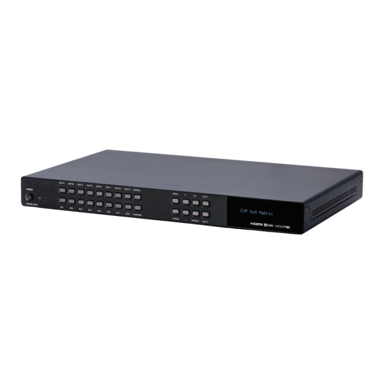
- Page 1 OR-88U-4K22 8×8 HDMI Matrix Switcher with 8 USB Power Outputs (4K/UHD, HDR, HDMI2.0, HDCP 2.2, 18Gbps) OPERATION MANUAL...
- Page 3 DISCLAIMERS The information in this manual has been carefully checked and is believed to be accurate. CYP (UK) Ltd assumes no responsibility for any infringements of patents or other rights of third parties which may result from its use. CYP (UK) Ltd assumes no responsibility for any inaccuracies that may be contained in this document.
- Page 4 SAFETY PRECAUTIONS Please read all instructions before attempting to unpack, install or operate this equipment and before connecting the power supply. Please keep the following in mind as you unpack and install this equipment: • Always follow basic safety precautions to reduce the risk of fire, electrical shock and injury to persons.
-
Page 5: Table Of Contents
CONTENTS 1. Introduction ...........6 2. Applications ...........6 3. Package Contents ........6 4. System Requirements ......7 5. Features ..........7 6. Operation Controls and Functions ..8 6.1 Front Panel ........... 8 6.2 Rear Panel ............. 9 6.3 Remote Control ........10 6.4 LCD Menu ...........11 6.5 IR Cable Pin Assignments .....12 6.6 RS-232 Protocol ........12 6.7 Telnet Control ..........13... -
Page 6: Introduction
1. INTRODUCTION This 4K UHD 8 by 8 Matrix provides the ability to connect up to eight 4K UHD HDMI sources to up to eight 4K UHD HDMI displays and freely switch between them. This unit comes with full support for 18Gbps (600Mhz) resolutions up to, and including 4K@60Hz (RGB &... -
Page 7: Features
HDMI source equipment such as media players, video game consoles or set-top boxes. HDMI receiving equipment such as HDTVs, monitors or audio amplifiers. The use of “Premium High Speed HDMI” cables is highly recommended. 5. FEATURES HDMI 2.0a and DVI 1.0 compliant HDCP 1.x and 2.2 compliant Eight HDMI inputs matrixed to eight HDMI outputs with 18Gbps (600MHz) 4K UHD support... -
Page 8: Operation Controls And Functions
6. OPERATION CONTROLS AND FUNCTIONS 6.1 Front Panel OUT A OUT B OUT C OUT D OUT E OUT F OUT G OUT H CANCEL MENU LOCK IN 1 IN 2 IN 3 IN 4 IN 5 IN 6 IN 7 IN 8 CONFIRM ENTER... -
Page 9: Rear Panel
MUTE: The “MUTE” button functions as a blank audio/video source. To use it, follow the standard matrix routing instructions, but use the “MUTE” button as the input to blank out the selected outputs. When a “MUTE” input is in use it will show up as “M” within the routing display. LCD WINDOW: Displays the unit’s menu, settings and information. -
Page 10: Remote Control
6.3 Remote Control POWER: Press to power the unit on or place it into stand-by mode. 1 / A 5 / E INFO 2 / B 6 / F MUTE 1/A ~ 8/H: Press these keys to configure the 3 / C 7 / G PRESET video routing. -
Page 11: Lcd Menu
6.4 LCD Menu LEVEL 1 LEVEL 2 LEVEL 3 LEVEL 4 Video Setup EDID Setup EDID Mode Appoint Mode All Mode Appoint Mode IN1 ~ IN8 EDID All Mode EDID IN1 ~ IN8 Preset Setup 1 ~ 8 Downscale A ~ H Setup Drivers Setup USB Power... -
Page 12: Ir Cable Pin Assignments
6.5 IR Cable Pin Assignments IR Extender IR Signal Power Ground 6.6 RS-232 Protocol UNIT REMOTE SYSTEM Definition Definition ► ◄ Baud Rate: 19200bps Data Bits: 8 Parity Bits: None Stop Bits: 1 Flow Control: None... -
Page 13: Telnet Control
6.7 Telnet Control Before attempting to use Telnet control, please ensure that both the unit and the PC/Laptop are connected to the same active networks. To access Telnet Click Start, type “cmd” in the search field, and In Windows 7 press Enter. -
Page 14: Rs-232 And Telnet Commands
6.8 RS-232 and Telnet Commands 6.8.1 General & System Commands COMMAND DESCRIPTION VARIABLES HELP Show the full command list. ? Show the full command list. SET FACTORY DEFAULT Reset all settings to the factory defaults. Unit will automatically reboot. SET FACTORY IPCONFIG DEFAULT Reset Ethernet settings to the factory defaults. - Page 15 6.8.1 General & System Commands COMMAND DESCRIPTION VARIABLES SET IR IN CHANNEL N1 N1 = 0 ~ 15 Set the IR remote channel to use. [IR Channel] GET IR IN CHANNEL Show the current IR remote channel. SET IR IN CUSTOM CODE N1 N1 = 0000 ~ 7FFF Set the IR custom code.
- Page 16 6.8.1 General & System Commands COMMAND DESCRIPTION VARIABLES GET KEYLOCK Show the current front panel key lock state. GET FW VER Show the unit’s firmware version. 6.8.2 Matrix Commands COMMAND DESCRIPTION VARIABLES SET OUT N1 ROUTE N2 N1 = A ~ H Route input N2 to output N1.
- Page 17 6.8.2 Matrix Commands COMMAND DESCRIPTION VARIABLES SET CURRENT ROUTE TO PRESET N1 N1 = 1 ~ 8 Save the current input/output routing [Preset Number] to preset N1. SET ROUTE PRESET N1 Load and activate routing preset N1. N1 = 1 ~ 8 [Preset Number] GET ROUTE PRESET N1...
- Page 18 6.8.2 Matrix Commands COMMAND DESCRIPTION VARIABLES SET OUT N1 NAME N2 N1 = A ~ H Set the name of output N1 to N2. [Output Port] N2 = {Output Name, 32 chars max} GET OUT N1 NAME N1 = A ~ H Show the current name of input N1.
- Page 19 6.8.3 Test Pattern Commands COMMAND DESCRIPTION VARIABLES SET PATTERN N1 TIMING N2 N1 = A ~ H Set the output timing and resolution [Output Port] for the test pattern on output N1. Available values for N2: [720p@60Hz] [1080p@60Hz] [720p@50Hz] [1080p@50Hz] [4K@25Hz] [4K@30Hz] [4K@50Hz]...
- Page 20 6.8.4 EDID Commands COMMAND DESCRIPTION VARIABLES SET ALL IN EDID MODE N1 Available values for N1: Enable or disable the “All Input” EDID mode. [All Input] [Appoint] GET ALL IN EDID MODE Show the current “All Input” EDID mode state. SET ALL IN EDID N1...
- Page 21 6.8.4 EDID Commands COMMAND DESCRIPTION VARIABLES GET ALL IN EDID Show the EDID selected for use in the “All Input” EDID mode. SET IN N1 EDID N2 N1 = 1 ~ 8 Set EDID N2 as the EDID to use with [Input Port] input N1 in “Appoint”...
- Page 22 6.8.4 EDID Commands COMMAND DESCRIPTION VARIABLES GET IN N1 EDID N1 = 1 ~ 8 Show the EDID currently used with [Input Port] input N1. GET ALL IN EDID LIST Show the current EDID selections for all inputs. GET IN EDID LIST Show the full list of available EDIDs.
- Page 23 6.8.5 HDCP Commands COMMAND DESCRIPTION VARIABLES SET IN N1 HDCP MODE N2 N1 = 1 ~ 8 Set the HDCP mode for input N1. [Input Port] Available values for N2: [HDCP Disabled] [Follow Source] [Follow Display] GET IN N1 HDCP MODE N1 = 1 ~ 8 Show the current HDCP mode of input [Input Port]...
- Page 24 6.8.5 HDCP Commands COMMAND DESCRIPTION VARIABLES GET OUT N1 HDCP ABILITY N1 = A ~ H Show the HDCP capability detected [Output Port] from the display connected to output Available result codes: [No HDCP] [HDCP 1.x] [HDCP 2.2] 6.8.6 Ethernet Commands COMMAND DESCRIPTION VARIABLES...
- Page 25 6.8.6 Ethernet Commands COMMAND DESCRIPTION VARIABLES GET GATEWAY Show the current gateway. GET MAC ADDR Show the MAC address. SET TELNET PORT N1 N1 = 0 ~ 65535 Set the Telnet port. [Port Number] GET TELNET PORT Show the current Telnet port. GET HOSTNAME...
-
Page 26: Webgui Control
6.9 WebGUI Control Device Discovery APP Please obtain the “Device Discovery” software from your authorised dealer and save it in a directory where you can easily find it. Connect the unit and your PC/Laptop to the same active network and execute the “Device Discovery”... - Page 27 WebGUI Control Page By default, both the Username and Password are “admin” for the WebGUI. The administrator password can be changed within the “System Settings” tab of the WebGUI if desired. The following function tabs will always display on left side of the WebGUI to aid with navigation. Note: The unit’s default IP address is 192.168.1.50.
- Page 28 Video Routing To begin assigning a new video route, please click the button of the HDMI output you wish to send video to and then click on the button of the preferred HDMI input port. If desired, you may select more than one output prior to selecting the input.
- Page 29 Output Edit A variety of output settings, including name, muting, test pattern configuration, downscaling, and OSD options can be configured here. Please click the “Edit” icon ( ) to open up the Output Edit window. - Set Output Name: To rename the output port, type the new name in the space provided in the Edit window.
- Page 30 will be automatically downscaled to 1080p while maintaining the original framerate. - OSD: This switch enables or disables the custom text display for this output. When enabled, the OSD text will be displayed in the upper- left corner of the selected output. - OSD Text Settings: Each output can display up to 2 lines of customised OSD text.
- Page 31 Preset Setting This matrix can store up to eight video routing presets. Presets can be utilised to store multiple different routing states in advance for rapid, hassle-free, recall. - Store: Once you have the matrix set the way you like, you can click the “Preset Store”...
- Page 32 2. EDID Settings This matrix provides the option of six standard EDIDs, eight sink sourced EDIDs and eight user uploaded EDIDs that can be assigned to each input port individually. The names of the eight user uploaded EDIDs can changed if desired. Customer EDID Settings To upload a user EDID, please click the “Upload”...
- Page 33 PC. To change the name of a Customer EDID, type the new name in the space provided, then click on the “Save Name” button. Sink EDID Download To save the EDID from one of the connected displays to your local PC, select the appropriate sink from the dropdown list then press the “Download”...
- Page 34 3. Device Settings This page provides control over the matrix’s hardware related settings and options including USB port power, IR and fan control. USB Power Supply Provides controls to turn the power supplied by each USB port on or off. IR Channel Use the dropdown to select the IR channel used to control the matrix using the included remote.
- Page 35 4. User Config This tab provides User Configuration options including changing the password for the Administrator account, and both the user name and password for the General User account. Note: The General User account has limited access to the WebGUI and can only change video routing, store/recall presets, and modify the General User’s own account settings.
- Page 36 5. System Settings This tab provides system information, power control, Ethernet configuration options, system configuration backup/restore, and firmware update functions. Power Press this switch to toggle the unit’s power between ON and OFF (standby mode). Note: While in standby mode the unit’s WebGUI, Telnet and RS-232 controls are still active.
- Page 37 Restore Current Configuration Previously saved system configurations may be restored from a saved XML file. Click the “Choose File” button to locate the saved XML file, then click the “Restore” button. Reset to Default Press this button to reset the unit to its factory default state. After the reset is complete, the unit will reboot automatically.
-
Page 38: Connection Diagram
7. CONNECTION DIAGRAM Blu-ray Players Set-top Boxes RS-232 Wireless Equipped PC/ HDMI Inputs Router Laptop RS-232 Power Supply USB 5V/1A OUT IR IN CONTROL RS232 SERVICE DC 24V HDMI IN HDMI OUT 60° 1 / A 5 / E INFO 2 / B 6 / F MUTE... -
Page 39: Specifications
8. SPECIFICATIONS 8.1 Technical Specifications Video Bandwidth 600MHz/18Gbps Input Ports 8×HDMI Output Ports 8×HDMI 8×USB Type A (Power only, 5V/1A) Control Interfaces 1×IR Extender (3.5mm) 1×RS-232 (9-pin D-sub) 1×IP Control (RJ45) Supported Resolutions 480i@60Hz - 4K@60Hz (4:4:4, 8-bit) VGA@60Hz - WUXGA@60Hz (RB) HDMI Cable Length 10m (1080p@60Hz, 12-bit) 5m (4K@60Hz, RGB &... -
Page 40: Video Specifications
8.2 Video Specifications Supported PC Resolutions (Hz) Input Output 640×480 60, 72, 75, 85 720×400 800×600 56, 60, 72, 75, 85 1024×768 60, 70, 75, 85 1152×864 1280×768 60, 75 ... - Page 41 Supported TV Resolutions (Hz) Input Output 720×480i 59.94, 60 720×576i 720×480p 59.94, 60 720×576p 1280×720p 50, 59.94, 60 1920×1080i 1920×1080p 23.97, 24, 25, 29.97, 30, 59.94, 60 ...
-
Page 42: Acronyms
9. ACRONYMS ACRONYM COMPLETE TERM Consumer Electronics Control Command Line Interface Digital Visual Interface EDID Extended Display Identification Data Graphical User Interface High-Definition HDCP High-bandwidth Digital Content Protection HDMI High-Definition Multimedia Interface High Dynamic Range HTTP HyperText Transfer Protocol Internet Protocol Infrared Liquid-Crystal Display LPCM... - Page 44 CYP (UK) Ltd., Unit 7, Shepperton Business Park, Govett Avenue, Shepperton, Middlesex, TW17 8BA Tel: +44 (0) 20 3137 9180 | Fax: +44 (0) 20 3137 6279 Email: sales@cypeurope.com www.cypeurope.com v1.02...
Need help?
Do you have a question about the OR-88U-4K22 and is the answer not in the manual?
Questions and answers