Table of Contents
Advertisement
Quick Links
Advertisement
Table of Contents

Subscribe to Our Youtube Channel
Related Manuals for CYP PU-8H8HBT


Summary of Contents for CYP PU-8H8HBT
- Page 1 PU-8H8HBT 8 x 8 HDMI HDBaseT™ Matrix (inc. PoE) OPERATIONS MANUAL...
-
Page 3: Copyright Notice
DISCLAIMERS The information in this manual has been carefully checked and is believed to be accurate. CYP (UK) Ltd assumes no responsibility for any infringements of patents or other rights of third parties which may result from its use. CYP (UK) Ltd assumes no responsibility for any inaccuracies that may be contained in this document. -
Page 4: Safety Precautions
SAFETY PRECAUTIONS Please read all instructions before attempting to unpack, install or operate this equipment and before connecting the power supply. Please keep the following in mind as you unpack and install this equipment: • Always follow basic safety precautions to reduce the risk of fire, electrical shock and injury to persons. -
Page 5: Table Of Contents
CONTENTS 1. Introduction ...........6 2. Applications ...........6 3. Package Contents ........6 4. System Requirements ......6 5. Features ..........7 6. Operation Controls and Functions ..8 6.1 Front Panels ..........8 6.2 Rear Panels ........... 9 6.3 Side Panel ...........10 6.4 Remote Control ........10 6.5 IR Pin Assignment ........11 6.6 RS-232 Protocols ........12 6.7 RS-232 Commands ........13... -
Page 6: Introduction
CAT5e/6 cable infrastructure. This single box solution will enable an installer to confidently integrate an eight zone multi-room AV system. The PU-8H8HBT is designed to be used with the PU-507-RX Receiver which can utilise the Power over Ethernet (PoE) capabilities of the matrix. -
Page 7: Features
5. FEATURES Supports all v1.3 HDMI resolutions Supports uncompressed video/audio up to 10.2Gbps Common supported resolutions: HDTV: 480p, 576p, 720p, 1080i, 1080p, 1080p24; PC: VGA, SVGA, XGA, WXGA, SXGA, UXGA, WUXGA. HDMI, HDCP and DVI complaint High Definition Audio supported: Dolby TrueHD, Dolby Digital Plus and DTS-HD Master Audio plus LPCM (up to 192kHz) Uncompressed data transfer over single CAT cable (100m - CAT6;... -
Page 8: Operation Controls And Functions
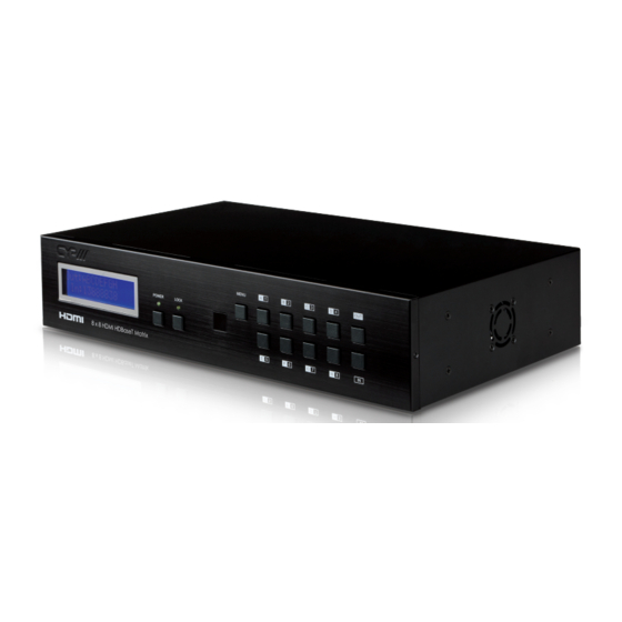
6. OPERATION CONTROLS AND FUNCTIONS 6.1 Front Panels MENU POWER LOCK LCD Display: Displays the setting information of each input and output selection. Power button LED: Press this button to power the device on/off. The LED will illuminate green when the power is on, red when it is in 'Standby' mode. -
Page 9: Rear Panels
6.2 Rear Panels IR OUT IR OUT IR OUT IR OUT IR OUT IR OUT IR OUT IR OUT IR OUT CAT5e/6 OUT CAT5e/6 OUT CAT5e/6 OUT CAT5e/6 OUT CAT5e/6 OUT CAT5e/6 OUT CAT5e/6 OUT CAT5e/6 OUT POE 24V IR IN IR IN IR IN IR IN... -
Page 10: Side Panel
6.3 Side Panel Fan Ventilator: These are air ventilation areas, DO NOT block these areas or cover it with any object. Please allow adequate space around the unit for air circulation 6.4 Remote Control Power: Press this button to switch on the device or set it to standby mode. -
Page 11: Ir Pin Assignment
6.5 IR Pin Assignment IR Blaster Power 5 V IR Blaster Signal IR Receiver IR Signal Power 5 V Grounding... -
Page 12: Rs-232 Protocols
6.6 RS-232 Protocols Pin Assignment CMSI-8H8CV Remote Control Console Assignment Assignment Baud Rate: 19200bps Data bit: 8 bits Parity: None Stop Bit: 1 Flow Control: None... -
Page 13: Rs-232 Commands
6.7 RS-232 Commands Command (Case Description Sensitive) A1~A8 Switch output A to 1~8 B1~B8 Switch output B to 1~8 C1~C8 Switch output C to 1~8 D1~D8 Switch output D to 1~8 E1~E8 Switch output E to 1~8 F1~F8 Switch output F to 1~8 G1~G8 Switch output G to 1~8 H1~H8... -
Page 14: Connection Diagram
7. CONNECTION DIAGRAM ZONE ZONE ZONE ZONE Power Power Power Link Link Link Power Link IR 1 IR 2 IR 1 IR 2 IR 1 IR 2 IR 1 IR 2 Extender Blaster RS232 Out CAT5e/6 In Extender Blaster RS232 Out CAT5e/6 In Extender Blaster RS232 Out... - Page 15 ZONE ZONE ZONE ZONE Displays HDMI Outputs IR Out/In Receiver Units Power Power Power Power Link Link Link Link IR 1 IR 2 IR 1 IR 2 IR 1 IR 2 IR 1 IR 2 Extender Blaster RS232 Out CAT5e/6 In Extender Blaster RS232 Out CAT5e/6 In...
-
Page 16: Specifications
8. SPECIFICATIONS Max. TMDS Bandwidth 6.75 G bps Input Ports 8×HDMI, 9×IR Extender, 1×RS-232, 1×Mini USB-B type(for firmware update only) Output Ports 8×CAT5e/6/7, 9×IR Blaster ESD Protection Human body model: ± 8kV (Air-gap discharge) ± 4kV (Contact discharge) Power Supply 24 V/6.25 A DC (US/EU standards, CE/ FCC/UL certified) Dimensions 438 mm(W)×255 mm(D)×93 mm(H) Weight 4458 g Chassis Material Metal Silkscreen Color Black Operating Temperature 0 º C ~40 º C /32 º F ~104 º F Storage Temperature −20 º... -
Page 17: Acronyms
9. ACRONYMS ACRONYM COMPLETE TERM Digital Theater System Digital Visual Interface EDID Extended Display Identification Data HDCP High-bandwidth Digital Content Protection HDMI High-Definition Multimedia Interface HDTV High-Definition Television Liquid Crystal Monitor Universal Serial Bus UXGA Ultra Extended Graphics Array Video Graphics Array... - Page 20 CYP (UK) Ltd., Unit 7, Shepperton Business Park, Govett Avenue, Shepperton, Middlesex, TW17 8BA Tel: +44 (0) 20 3137 9180 | Fax: +44 (0) 20 3137 6279 Email: sales@cypeurope.com www.cypeurope.com...
Need help?
Do you have a question about the PU-8H8HBT and is the answer not in the manual?
Questions and answers