
Subscribe to Our Youtube Channel
Related Manuals for CYP CPLUS-401V


Summary of Contents for CYP CPLUS-401V
- Page 1 CPLUS-401V 4×1 HDMI Switcher with Stereo Amplifier Operation Manual Operation Manual...
- Page 2 ® registered trademarks of HDMI licensing Administrator, Inc.
- Page 3 DISCLAIMERS The information in this manual has been carefully checked and is believed to be accurate. Cypress Technology assumes no responsibility for any infringements of patents or other rights of third parties which may result from its use. Cypress Technology assumes no responsibility for any inaccuracies that may be contained in this document.
- Page 4 SAFETY PRECAUTIONS Please read all instructions before attempting to unpack, install or operate this equipment and before connecting the power supply. Please keep the following in mind as you unpack and install this equipment: • Always follow basic safety precautions to reduce the risk of fire, electrical shock and injury to persons.
-
Page 5: Table Of Contents
CONTENTS 1. Introduction ............1 2. Applications ............. 1 3. Package Contents ........... 2 4. System Requirements ........2 5. Features............3 6. Operation Controls and Functions ....4 6.1 Front Panel ..........4 6.2 Rear Panel........... 5 6.3 Remote Control ........... 6 6.3.1 IR Remote (Unit Control) .... -
Page 6: Introduction
1. INTRODUCTION This 4×1 HDMI Switch with Stereo Amplifier provides high performance audio and video support, including HDR and ARC, making it ideally suited for residential or corporate installations. Any of four high-bandwidth (18Gbps) HDMI sources may be routed to the HDMI output. 4K UHD HDMI video sources, up to and including 4K@60Hz (4:4:4, 8-bit) as well as 10/12- bit sources with HDR are supported, providing gorgeous video quality. -
Page 7: Package Contents
3. PACKAGE CONTENTS • 1× UHD HDMI/DP over Fiber Transceiver • 1× 12V/3A DC Power Adapter • 1× Power Cord • 1× 3-pin Terminal Block • 1× Shockproof Feet (Set of 4) • 1× Operation Manual 4. SYSTEM REQUIREMENTS • HDMI source equipment such as media players, video game consoles or set-top boxes. -
Page 8: Features
5. FEATURES • HDMI with HDR, 3D & 4K@60Hz support, DVI 1.0 compatible • HDCP 2.2 and HDCP 1.x compliant • Routes four HDMI sources to one HDMI output with support for automatic input switching • Supports up to 4K UHD (18Gbps, 4K@60Hz 4:4:4, 8-bit) video input and output •... -
Page 9: Operation Controls And Functions
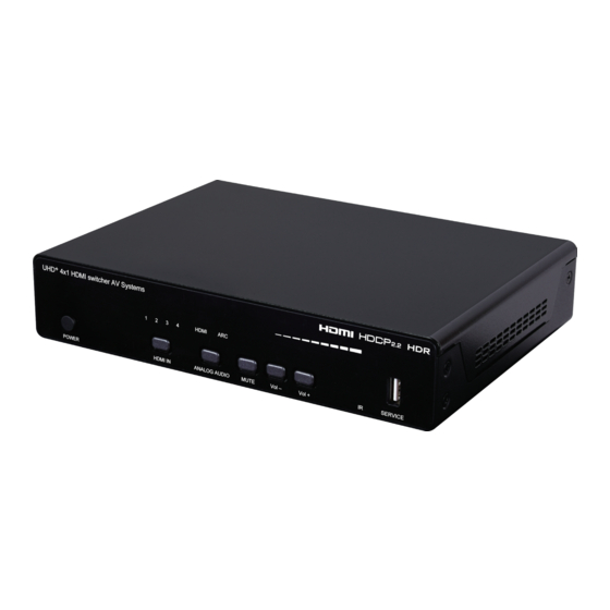
6. OPERATION CONTROLS AND FUNCTIONS 6.1 Front Panel UHD + 4x1 HDMI switcher AV Systems HDMI POWER HDMI IN ANALOG AUDIO MUTE Vol – Vol + SERVICE POWER Button and LED: Press this button to power the unit on (green LED) or place it into standby mode (red LED). -
Page 10: Rear Panel
6.2 Rear Panel RS-232 RIGHT LEFT IR OUT – – LINE OUT HDMI IN HDMI OUT CONTROL DC 24V HDMI IN 1~4 Ports: Connect to HDMI source equipment such as media players, game consoles or set-top boxes. HDMI OUT Port: Connect to an HDMI TV, monitor, or amplifier for digital video and audio output. -
Page 11: Remote Control
6.3 Remote Control 6.3.1 IR Remote (Unit Control) This unit’s IR remote provides control over the Adv. unit directly, as well as control over additional external devices through the assignment of learned IR commands. The following buttons, in “Standard” mode provide direct control over the unit itself. -
Page 12: Ir Remote (Assignable Buttons)
6.3.2 IR Remote (Assignable Buttons) • Standard Mode The function of the buttons on the bottom half of the IR remote are user defined within the WebGUI. They are used to tell the unit to transmit IR commands to the source device currently being viewed. - Page 13 Advanced Mode If the “Adv.” button is pressed, the unit will switch into the Adv. “Advanced” IR command mode, changing the functionality of these buttons to use additional IR commands that have been defined by the user within the WebGUI. Similar to the other user defined buttons, they are used to tell the unit to transmit IR commands to the source device currently being viewed.
-
Page 14: Ir Cable Pinouts
6.4 IR Cable Pinouts IR Extender IR Blaster Cable Cable Power Infrared Infrared Power Not Used Ground 6.5 RS-232 Pinout and Defaults Serial Port Default Settings Baud Rate 19200 Data Bits Parity Bits None Stop Bits Flow Control None DE-9 Female Port... -
Page 15: Webgui Control
6.6 WebGUI Control • Device Discovery Please obtain the “Device Discovery” software from your authorized dealer and save it in a directory where you can easily find it. Connect the unit and your PC/Laptop to the same active network and execute the “Device Discovery”... - Page 16 • WebGUI Overview After connecting to the WebGUI’s address in a web browser, the login screen will appear. Please enter the appropriate user name and password then click “Enter” to log in. Note: The default user name and password is “admin”. On the left side of the browser you will see the following menu tabs where all primary functions of the unit are controllable via the built in WebGUI.
-
Page 17: Video Switch Tab
6.6.1 Video Switch Tab This tab provides A/V routing control, auto switch controls, and I/O renaming options. To assign a new A/V route, please click the output button on the left and then click on the button of the preferred input port on the right. As you select each button they will become outlined in white. -
Page 18: Analog Audio Tab
„ Set Output Name: To rename the output, type the new name in the space provided in the Edit window. The name can be up to 32 characters long. Click the “Save” button to confirm the change. „ Auto Switch: Auto switching may be enabled or disabled for the output. - Page 19 1) Audio Source: Select the audio source type (HDMI or ARC) to route to the amplified analog output from the dropdown. Note: If the display connected to the HDMI output does not support ARC, no audio will be heard when the ARC source is selected. 2) Lip Sync: Allows the correction of lip sync issues by adjusting the audio delay from 0 to 150ms.
-
Page 20: Edid Settings Tab
6.6.3 EDID Settings Tab This tab provides the option of eight standard EDIDs, one sink sourced EDID, and four customer uploaded User EDIDs that can be assigned to any or all of the HDMI input ports. Detailed information about any of these EDIDs may also be viewed here. - Page 21 2) Output EDID „ Download: To save the EDID from a connected HDMI display to your local PC, select the sink from the dropdown list then press the “Download” button. Depending on your browser settings you will either be asked where to save the downloaded file, or the file will be transferred to the default download location on your PC.
- Page 22 This unit provides the following 8 default EDIDs: Unit’s default EDIDs FHD 2CH 1920×1080p@60Hz (4.95Gbps) & 8-bit color, LPCM 2.0 FHD Multi-CH 1920×1080p@60Hz (4.95Gbps) & 8-bit color, LPCM 7.1 & Bitstream UHD 2CH 3840×2160p@30Hz (10.2Gbps) & Deep Color (8/10/12-bit), LPCM 2.0 UHD Multi-CH 3840×2160p@30Hz (10.2Gbps) &...
-
Page 23: Ir Settings Tab
6.6.4 IR Settings Tab This tab provides control over the IR interfaces of the unit and how it interacts with the unit and with devices associated with each input and output. 1) IR Bypass: Enable or disable basic IR bypass from the front IR window, to the currently selected input’s IR blaster. -
Page 24: Ir Control Tab
6.6.5 IR Control Tab This tab provides control over the handling of all IR commands stored within the unit, including learning commands to be assigned to the buttons on the IR remote/App for each input and output, enabling the Advanced and Extension button sets, renaming each button, as well as saving/loading the IR configuration for each source or sink to/from a PC file. - Page 25 „ Advance: Enable or disable the availability of the “Advance” IR remote button set for the current Source or Sink. Note: The “Advance” buttons are available on both the IR remote and the app. „ Extension: Enable or disable the availability of the “Extension” IR remote button set for the current Source or Sink.
- Page 26 Note: Only buttons that have IR codes associated with them will be visible in the mobile device app. „ Key Name (“Extension” and “Source Controller” buttons only): Allows renaming the current button for easy identification. Type the new name in the space provided. The name can be up to 32 characters long.
- Page 27 „ Play Key Command Data: Contains the IR command data to be transmitted when the PLAY/PAUSE button is pressed. This data can be learned from an external remote or manually entered. Note: If separate Play and Pause commands are defined, they will be transmitted alternately with each press of the button.
-
Page 28: User Config Tab
„ Pause Key IR Learner: To learn an IR command from a physical IR remote click the “Learn” button. After selecting “Learn”, you have 15 seconds to point the IR remote at the appropriate IR Receiver and press the remote button to learn. After 15 seconds have passed, the learned IR command (if any) will be displayed in the Command Data space. -
Page 29: System Settings Tab
6.6.7 System Settings Tab This tab provides system information, power control, network configuration options, system configuration backup/restore/reset, and firmware update functions. 1) Serial Number/Firmware Version: Displays the unit’s serial number and current firmware version. 2) Power: Provides control over the unit’s power state. „... - Page 30 4) Network: IP mode may be switched between Static IP or DHCP. In Static IP mode the IP, netmask and gateway addresses may be manually set. When in DHCP mode, the unit will attempt to connect to a local DHCP server and obtain IP, netmask and gateway addresses automatically.
-
Page 31: Mobile Device App
6.7 Mobile Device App This unit may also be controlled via a dedicated mobile device control application which is available for download. Please contact your authorized dealer for details on how to obtain the app. The app provides flexible control over the unit, going beyond what the physical remote allows. -
Page 32: App Main Page
6.7.1 App Main Page The app’s Main page provides access to all of the IR commands available for the currently selected video source or display as defined within the unit’s WebGUI. This page also provides an easy way to switch inputs, change the amplified audio source, and control the amplified audio volume via the bottom Control Slider’s row of buttons. - Page 33 „ Normal IR Remote Buttons: These buttons share their functions with the buttons at the bottom of the unit’s physical remote, as defined within the unit’s WebGUI. Pressing any of these buttons will send the defined IR command to the IR Blaster associated with the current input or local display.
-
Page 34: App Unit Control Slider
6.7.2 App Unit Control Slider This slider at the bottom of the app’s main page provides an easy way to switch inputs, change the amplified audio source, control the amplified audio volume, or select the local display for IR control. To access the additional buttons on the slider, slide the menu bar to the left or right. -
Page 35: App Selection Menu Page
2) Info „ CYP Product: Links to a web page with information about other products available from the company. „ APP Version: Displays information about the App version and Unit... -
Page 36: Telnet Control
6.8 Telnet Control Before attempting to use Telnet control, please ensure that both the unit and the PC are connected to the same active networks. Start your preferred Telnet/Console client, or use the built in client provided by most modern computer operating systems. After starting the client, connect by using the current IP address of the unit and port 23 (if the communication port number used by the unit has not been changed previously). - Page 37 COMMAND Description and Parameters get fw ver Show the unit’s current firmware version. set system reboot Reboot the unit. set description N1 Set the description/name of the unit. N1 = {Name} [64 characters max] get description Show the unit’s current description/name. set keylock N1...
- Page 38 COMMAND Description and Parameters get auto standby timer Show the current auto standby timer setting. set factory default Reset all configurations to the factory defaults. get in port number Report the number of inputs supported by the unit get in type list List the interface supported by each input.
- Page 39 COMMAND Description and Parameters set in N1 edid N2 Set the EDID to use on the specified input. N1 = 1~4 [HDMI Input] Available values for N2: [Internal FHD 2CH] [Internal FHD Multi-CH] [Internal UHD 2CH] [Internal UHD Multi-CH] [Internal UHD+ 2CH] [Internal UHD+ Multi-CH] [Internal HDR 2CH] [Internal HDR Multi-CH]...
- Page 40 COMMAND Description and Parameters get in N1 power control Show the current state of the auto power control setting for the specified input. N1 = 1~4 [HDMI Input] get out port number Show the total number of outputs on the unit. get out type list...
- Page 41 COMMAND Description and Parameters set out A power control N1 Enable or disable the auto power control feature for the HDMI output. Available values for N1: [Enable Power Control] [Disable Power Control] get out A power control Show the current state of the auto power control setting for the HDMI output.
- Page 42 COMMAND Description and Parameters get user N1 edid data Show the EDID used by the specified User EDID as ASCII hex data. N1 = 1~4 [User EDID number] get user N1 edid information Show English readable details from the specified User EDID. N1 = 1~4 [User EDID number] set analog audio route N1...
- Page 43 COMMAND Description and Parameters set amplifier volume N1 Set the volume level of the amplified audio output. Available values for N1: 0~80 [Volume in 0.5dB steps] [Increase volume 1 step] DOWN [Decrease volume 1 step] get amplifier volume Show the current volume level of the amplified audio output. set amplifier left enhance N1...
- Page 44 COMMAND Description and Parameters set amplifier eq N1 gain N2 Set the audio equalizer level at the specified frequency band for the amplified audio output. Available values for N1: [64Hz band] [125Hz band] [250Hz band] [500Hz band] 1000 [1kHz band] 2000 [2kHz band] 4000...
- Page 45 COMMAND Description and Parameters set ip addr N1 Set the unit’s static IP address. N1 = X.X.X.X [X = 0~255, IP address] get ip addr Show the unit’s current IP address. set netmask Set the unit’s static netmask. N1 = X.X.X.X [X = 0~255, netmask] get netmask...
- Page 46 COMMAND Description and Parameters set webgui login timeout N1 Set the WebGUI inactivity timeout value. Available values for N1: [No timeout] 1~65535 [Timeout in minutes] get webgui login timeout Show the current WebGUI inactivity timeout value. set ethernet default Reset the Ethernet settings to their factory defaults. set ir N1 remote control name N2...
- Page 47 COMMAND Description and Parameters set ir N1 learn to N2 func N3 Set the IR receiver location to use when learning IR command N3 assigned to the device connected to input/output port N2 and activate the learning function. Available values for N1: [Front IR window] Available values for N2: [HDMI Input device]...
- Page 48 COMMAND Description and Parameters get ir N1 advance mode Show the current “Advance mode” setting for the specified device’s remote control. Available values for N1: [HDMI Input device] [HDMI Output device] set ir N1 extension mode N2 Enable or disable the “Extension mode” for the specified device’s remote control.
- Page 49 COMMAND Description and Parameters get ir N1 default mode Show the current default mode screen shown in the app for the specified device’s remote control. Available values for N1: [HDMI Input device] [HDMI Output device] set ir N1 toggle mode N2 Enable or disable the ability of the “Play/Pause”...
- Page 50 COMMAND Description and Parameters get ir N1 extension N2 name Show the current name for the specified device’s Extension mode remote control function button N2. Available values for N1: [HDMI Input device] [HDMI Output device] N2 = 32, 34, 39~60 [IR button function number] set ir bypass N1...
- Page 51 COMMAND Description and Parameters set osd font size N1 Set the font size for the OSD banner. Available values for N1: [Normal] [Large] get osd font size Show the current font size for the OSD banner. set osd font color N1 Set the color of the font used by the OSD banner.
- Page 52 COMMAND Description and Parameters set osd freerun color N1 Set the freerun color to use when the current input does not have a valid source. Available values for N1: [Disable freerun] [Red] [Green] [Blue] [Black] [Color bars] get osd freerun color Show the current freerun color.
-
Page 53: Connection Diagram
7. CONNECTION DIAGRAM RS-232 Equipped PC Headphones Media Players Speakers RS-232 Stereo Output 1.5m 1.5m 1.5m 1.5m Amplified Stereo Output 60° 60° 60° 60° Power Supply IR Outputs RS-232 RIGHT LEFT IR OUT – – LINE OUT HDMI IN HDMI OUT CONTROL DC 24V HDMI Inputs... -
Page 54: Specifications
8. SPECIFICATIONS 8.1 Technical Specifications HDMI Bandwidth 18Gbps Input Ports 4×HDMI (Type-A) Output Ports 1×HDMI (Type-A) 1×Analog Stereo (2× 2-pin Terminal Block) 1×Analog Stereo (3.5mm) Pass-through Ports 5×IR Blaster (3.5mm) Control Ports 1×RS-232 (DE-9) 1×IP Control (RJ-45) Service Port 1×USB 2.0 (Type-A) IR Frequency 30 ~ 50kHz (30 ~ 60kHz under ideal conditions) -
Page 55: Video Specifications
8.2 Video Specifications Input Output Supported Resolutions (Hz) HDMI HDMI 720×400p@70/85 640×480p@60/72/75/85 720×480i@60 720×480p@60 720×576i@50 720×576p@50 800×600p@56/60/72/75/85 848×480p@60 1024×768p@60/70/75/85 1152×864p@75 1280×720p@50/60 ... - Page 56 Input Output Supported Resolutions (Hz) HDMI HDMI 2560×1440p@60RB 2560×1600p@60RB 2048×1080p@24/25/30 2048×1080p@50/60 3840×2160p@24/25/30 3840×2160p@50/60 (4:2:0) 3840×2160p@24, HDR10 3840×2160p@50/60 (4:2:0), HDR10 3840×2160p@50/60 4096×2160p@24/25/30 ...
-
Page 57: Audio Specifications
8.3 Audio Specifications 8.3.1 Digital Audio HDMI Input / Output LPCM Max Channels 8 Channels Sampling Rate (kHz) 32, 44.1, 48, 88.2, 96, 176.4, 192 Bitstream Supported Formats Standard & High-Definition 8.3.2 Analog Audio Analog Output (Amplified) Max Power Level 20W+20W THD+N <... -
Page 58: Cable Specifications
8.4 Cable Specifications 1080p 4K30 4K60 (4:4:4) (4:4:4) Cable Length 8-bit 12-bit 8-bit 8-bit High Speed HDMI Cable HDMI Input HDMI Output Bandwidth Category Examples: • 1080p (FHD Video) - Up to 1080p@60Hz, 12-bit color - Data rates lower than 5.3Gbps or below 225MHz TMDS clock •... -
Page 59: Acronyms
9. ACRONYMS ACRONYM COMPLETE TERM Audio Return Channel ASCII American Standard Code for Information Interchange Audio/Video Cat.5e Enhanced Category 5 cable Cat.6 Category 6 cable Cat.6A Augmented Category 6 cable Cat.7 Category 7 cable Consumer Electronics Control Command-Line Interface Digital-to-Analog Converter Decibel DHCP Dynamic Host Configuration Protocol... - Page 60 ACRONYM COMPLETE TERM Transmission Control Protocol THD+N Total Harmonic Distortion plus Noise 4K UHD 4K Ultra-High-Definition (10.2Gbps max) 4K UHD 4K Ultra-High-Definition (18Gbps max) Universal Serial Bus WUXGA (RB) Widescreen Ultra Extended Graphics Array (Reduced Blanking) Extended Graphics Array Ω...
- Page 64 CYPRESS TECHNOLOGY CO., LTD. www.cypress.com.tw...
Need help?
Do you have a question about the CPLUS-401V and is the answer not in the manual?
Questions and answers