
Related Manuals for HP ZBOOK STUDIO 16 G10


Summary of Contents for HP ZBOOK STUDIO 16 G10
- Page 1 Maintenance and Service Guide SUMMARY This guide provides maintenance information about such topics as spare parts, removal and replacement of parts, security, and backing up.
- Page 2 HP Inc. to be bound by the terms of the HP End Not all features are available in all under license. Chrome is a trademark of User License Agreement (EULA).
- Page 3 Safety warning notice Reduce the possibility of heat-related injuries or of overheating the computer by following the practices described. WARNING! To reduce the possibility of heat-related injuries or of overheating the computer, do not place the computer directly on your lap or obstruct the computer air vents. Use the computer only on a hard, flat surface.
-
Page 4: Table Of Contents
Table of contents 1 Product description............................................. 1 2 Components................................................5 Locating hardware ............................................5 Locating software............................................5 Right..................................................5 Left................................................... 6 Display .................................................. 8 Low blue light mode (select products only)..............................8 Keyboard area..............................................9 Touchpad ...............................................10 Touchpad settings .......................................10 Adjusting touchpad settings................................10 Turning on the touchpad ..................................10 Touchpad components ....................................10... - Page 5 RTC battery ............................................73 Top speakers............................................74 Audio jack..............................................75 Top cover with keyboard ......................................76 6 Computer Setup (BIOS), TPM, and HP Sure Start ..............................78 Using Computer Setup ...........................................78 Navigating and selecting in Computer Setup ............................78 Restoring factory settings in Computer Setup............................79 Updating the BIOS .........................................
- Page 6 Backing up information and creating recovery media........................... 82 Using Windows tools for backing up................................. 82 Using the HP Cloud Recovery Download Tool to create recovery media (select products only)......82 Restoring and recovering your system..................................83 Creating a system restore ......................................83 Restoring and recovery methods ..................................83...
- Page 7 Using HP Sure Start (select products only)................................98 11 Power cord set requirements.........................................99 Requirements for all countries ......................................99 Requirements for specific countries and regions.............................99 12 Recycling................................................102 Index....................................................103...
-
Page 8: Product Description
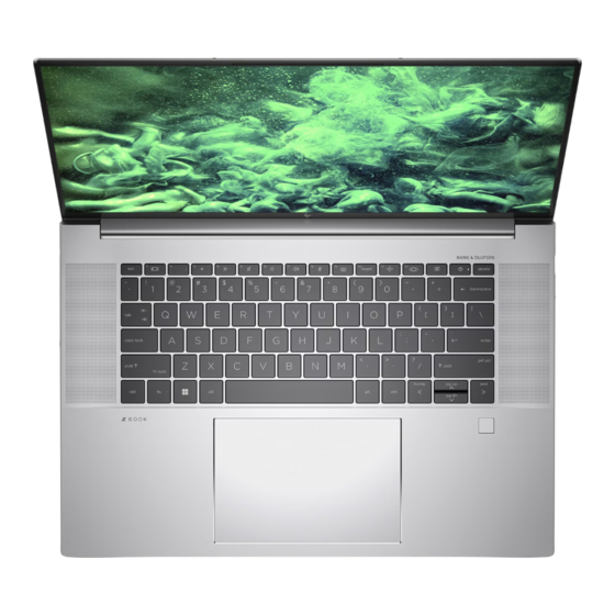
Category Description Product Name HP ZBook Studio 16 inch G10 Mobile Workstation PC Processors Intel® Core® i9-13900H 2.6 GHz processor (14 cores, 24 MB L3 cache, 45 W) Intel Core i9-13900HK 2.6 GHz processor (14 cores, 24 MB L3 cache, 45 W) Intel Core i7-13800H 2.5 GHz processor (14 cores, 24 MB L3 cache, 45 W) - Page 9 512 GB, M.2 2280, PCIe-4×4, NVMe, self-encrypting solid-state drive with TLC and OPAL2 Audio and video Audio brand: BANG and OLUFSEN Support for quad speakers HP True Vision Camera: integrated, high-definition (HD), USB 2.0, narrow field-of-view (NFOV), fixed, infrared (IR) Dual-array microphone Chapter 1 Product description...
- Page 10 6 cell, 86 Whr, Long Life, polymer battery HP Fast Charge Technology 200 W HP Smart AC adapter (power factor correction [PFC], right-angle barrel, slim 4.5 mm, 3 pin) 150 W HP Smart AC adapter (power factor correction [PFC], right-angle barrel, slim 4.5 mm, 3 pin) C13, 1.8 m (6.0 ft), HF power cord (conventional with sticker and straight plug)
- Page 11 Table 1-1 Product components and their descriptions (continued) Category Description Security Fingerprint reader HP combination nano cable lock HP essential combination nano cable lock Sensor Ambient light sensor Operating system FreeDOS Windows® 11 Home Windows 11 Home Single Language Windows 11 Pro...
-
Page 12: Components
Components Your computer features top-rated components. This chapter provides details about your components, where they are located, and how they work. Locating hardware Use these instructions to find out what hardware is installed on your computer. ■ Select the Search icon (select products only) in the taskbar, type device manager in the search box, and then select the Device Manager app. -
Page 13: Left
– and – Connects a display device that has a USB Type-C connector, providing DisplayPort output. USB port with 5 Gbps signaling rate and HP Connects a USB device, provides high-speed data transfer, Sleep and Charge and charges small devices (such as a smartphone), even when the computer is off. - Page 14 USB Type-C 40 Gbps signaling rate power Connect an AC adapter that has a USB Type-C connector, connector and Thunderbolt port with HP supplying power to the computer and, if needed, charging the Sleep and Charge and DisplayPort output (2) computer battery.
-
Page 15: Display
For additional safety information, see the Regulatory, Safety, and Environmental Notices . To access this guide: ■ Select the Search icon in the taskbar, type HP Documentation in the search box, and then select HP Documentation. NOTE: When a device is connected to the jack, the computer speakers are disabled. -
Page 16: Keyboard Area
For wireless regulatory notices, see the section of the country or region. To access this guide: ■ Select the Search icon in the taskbar, type HP Documentation in the search box, and then select HP Documentation. Keyboard area Keyboards can vary by language. Keyboard area... -
Page 17: Touchpad
NOTE: The keyboard, including the function keys and power button (select products only), is disabled in stand, tent, and tablet modes. To enable the keyboard, including the power button, change to the clamshell mode. Touchpad The touchpad settings and components are described here. Touchpad settings You learn how to adjust the touchpad settings and components here. -
Page 18: Lights
Table 2-4 Touchpad components and their descriptions Component Description Touchpad zone Reads your finger gestures to move the pointer or activate items on the screen. Left control zone Textured area that allows you to perform additional gestures. Right control zone Textured area that allows you to perform additional gestures. - Page 19 Table 2-5 Lights and their descriptions Component Description Caps lock light On: Caps lock is on, which switches the key input to all capital letters. Privacy key light (select products only) On: Privacy screen is on, which helps prevent side-angle viewing.
-
Page 20: Button, Speakers, And Fingerprint Reader
Button, speakers, and fingerprint reader Fingerprint readers can be located on the touchpad, on a side panel of the computer, or on the top cover below the keyboard. IMPORTANT: To verify that your computer supports fingerprint reader sign-in, select the Search icon in the taskbar, type Sign-in options in the search box, and then select the Sign-on options app. -
Page 21: Special Keys
Table 2-6 Button, speakers, and fingerprint reader and their descriptions (continued) Component Description Power button ● When the computer is off, press the button briefly to turn on the computer. ● When the computer is on, press the button briefly to initiate Sleep. - Page 22 Table 2-7 Special keys and their descriptions Component Description Displays system information when pressed in combination with the key. Executes frequently used system functions when pressed in combination with another key. Such key combinations are hot keys . called Windows key Opens the Start menu.
-
Page 23: Bottom
Table 2-7 Special keys and their descriptions (continued) Component Description Power button ● When the computer is off, press the button briefly to turn on the computer. ● When the computer is on, press the button briefly to initiate Sleep. ●... -
Page 24: Labels
Your service label will resemble one of the following examples. Refer to the illustration that most closely matches the service label on your computer. Table 2-9 Service label components and their descriptions Component Serial number Product ID HP product name Labels... - Page 25 Table 2-10 Service label components and their descriptions Component HP product name Product ID Serial number Warranty period Table 2-11 Service label components and their descriptions Component HP product name Warranty period Product ID Serial number ● Regulatory labels—Provide regulatory information about the computer.
-
Page 26: Illustrated Parts Catalog
To identify the computer major components, use this illustration and table. NOTE: HP continually improves and changes product parts. For complete and current information about supported parts for your computer, go to http://partsurfer.hp.com, select your country or region, and then follow the on-screen instructions. NOTE: Details about your computer, including model, serial number, product key, and length of warranty, are on the service tag at the bottom of your computer. - Page 27 Table 3-1 Computer major component descriptions and part numbers Item Component Spare part number Display assembly: Display spare parts are available as subcomponents, not as whole units. Display subcomponent spare parts are available. For spare part information, see Display assembly subcomponents on page Top cover with keyboard with backlight and Z Command key for use with computer models N10946-xxx equipped with an RGB webcam (includes backlight cable and keyboard cable;...
- Page 28 Table 3-1 Computer major component descriptions and part numbers (continued) Item Component Spare part number For use in Denmark, Finland, and Norway -DH1 For use in France -051 For use in French Canada -DB1 For use in Germany -041 For use in Greece -151 For use in Hungary -211...
- Page 29 Table 3-1 Computer major component descriptions and part numbers (continued) Item Component Spare part number (5a) Touchpad N10923-001 NOTE: The touchpad spare part kit does not include the touchpad cable. The touchpad cable is included in the Cable Kit, spare part number N10935-001. (5b) Touchpad cable (included in the Cable Kit, spare part number N10935-001) (6a)
- Page 30 Table 3-1 Computer major component descriptions and part numbers (continued) Item Component Spare part number Equipped with an Intel i9-13900H processor, an NVIDIA RTX A3X graphics controller with 8 GB N50993-001 of discrete memory, and a non-Windows operating system Equipped with an Intel i9-13900HK processor, an NVIDIA RTX A2X graphics controller with 8 GB N50988-601 of discrete memory, and the Windows 11 operating system Equipped with an Intel i9-13900HK processor, an NVIDIA RTX A2X graphics controller with 8 GB...
- Page 31 Table 3-1 Computer major component descriptions and part numbers (continued) Item Component Spare part number Equipped with an Intel i7-13800H processor, an NVIDIA RTX 4070 graphics controller with 8 GB N50978-001 of discrete memory, and a non-Windows operating system Equipped with an Intel i7-13800H processor, an NVIDIA RTX A1X graphics controller with 6 GB of N50983-601 discrete memory, and the Windows 11 operating system Equipped with an Intel i7-13800H processor, an NVIDIA RTX A1X graphics controller with 6 GB of...
-
Page 32: Display Assembly Subcomponents
Table 3-1 Computer major component descriptions and part numbers (continued) Item Component Spare part number System Board Repair Kit (not illustrated) N56255-888 (11) Heat sink (includes captive screws and replacement thermal material): For use with system boards equipped with a graphics subsystem with discrete memory and an N10927-001 Intel i-9 or Intel i-8 processor For use with system boards equipped with a graphics subsystem with discrete memory and an... - Page 33 Table 3-2 Display component descriptions and part numbers Item Component Spare part number Display bezel N10930-001 Display Adhesive Kit (not illustrated) N10938-001 Hinge cover N10937-001 Display panel assembly: 40.6 cm (16.0 in), DreamColor, WQUXGA, antiglare, LED, UWVA, nTOP display panel assembly; N51321-001 typical brightness: 500 nits 40.6 cm (16.0 in), OLED, WQUXGA, brightview, UWVA, TOP display panel assembly;...
-
Page 34: Miscellaneous Parts
Spare part number AC adapters 280 W AC adapter (PFC, 3 pin, 7.4 mm barrel, slim) M52952-001 200 W HP Smart AC adapter (PFC, 4.5 mm barrel) L00895-003 200 W AC adapter (PFC, RC, 3 pin, 4.5 mm barrel) L74881-001 150 W HP Smart (PFC, 4.5 mm barrel, slim) - Page 35 M27885-001 HP Bluetooth travel mouse L62043-001 HP USB mouse L95713-001 HP USB External DV D+-RW Drive 747080-001 Plastics Kit (includes fingerprint reader foil, fingerprint reader insert, memory module thermal N51319-001 pads, SD card insert, webcam holder, and WLAN antenna cover) Power cord (C13, 1.8 m [6.0 ft], high frequency (HF), conventional with tag):...
- Page 36 Table 3-3 Miscellaneous part descriptions and part numbers (continued) Component Spare part number Power cord (C5, 1.0 m [3.3 ft], HF, conventional with sticker): For use in Denmark M79264-001 For use in Europe M79266-001 For use in Israel M82712-001 For use in Switzerland M79265-001 For use in the United Kingdom M82711-001...
- Page 37 Table 3-3 Miscellaneous part descriptions and part numbers (continued) Component Spare part number For use in India 491683-D61 For use in Israel 491683-BB1 For use in Italy 491683-061 For use in North America 491683-001 For use in the People's Republic of China 491683-AA1 For use in the South America 491683-L31...
-
Page 38: Removal And Replacement Procedures Preliminary Requirements
Removal and replacement procedures preliminary requirements Use this information to properly prepare to disassemble and reassemble the computer. Tools required You need the following tools to complete the removal and replacement procedures: ● Tweezers ● Nonconductive, nonmarking pry tool ● Magnetic Phillips P1 screwdriver Service considerations The following sections include some of the considerations that you must keep in mind during... -
Page 39: Electrostatic Discharge Information
IMPORTANT: Drives are fragile components. Handle them with care. To prevent damage to the computer, damage to a drive, or loss of information, observe these precautions: ● Before removing or inserting a hard drive, shut down the computer. If you are unsure whether the computer is off or in Hibernation, turn the computer on, and then shut it down through the operating system. -
Page 40: Preventing Electrostatic Damage To Equipment
Table 4-1 Static electricity occurrence based on activity and humidity Relative humidity Event Walking across carpet 7,500 V 15,000 V 35,000 V Walking across vinyl floor 3,000 V 5,000 V 12,000 V Motions of bench worker 400 V 800 V 6,000 V Removing dual in-line packages (DIPs) from plastic tube 400 V... -
Page 41: Grounding The Work Area
Use conductive field service tools, such as cutters, screwdrivers, and vacuums. ● Avoid contact with pins, leads, or circuitry. Recommended materials and equipment HP recommends certain materials and equipment to prevent static electricity: ● Antistatic tape ● Antistatic smocks, aprons, or sleeve protectors ●... -
Page 42: Cleaning Your Computer
Enabling HP Easy Clean (select products only) HP Easy Clean helps you to avoid accidental input while you clean the computer surfaces. This software disables devices such as the keyboard, touch screen, and touchpad for a preset amount of time so that you can clean all computer surfaces. -
Page 43: Cleaning Your Computer With A Disinfectant
Keep liquids away from the product. Avoid getting moisture in any openings. If liquid makes its way inside your HP product, it can cause damage to the product. Do not spray liquids directly on the product. Do not use aerosol sprays, solvents, abrasives, or cleaners containing hydrogen peroxide or bleach that might damage the finish. -
Page 44: Caring For Wood Veneer (Select Products Only)
Keep liquids away from the product. Avoid getting moisture in any openings. If liquid makes its way inside your HP product, it can cause damage to the product. Do not spray liquids directly on the product. Do not use aerosol sprays, solvents, abrasives, or cleaners containing hydrogen peroxide or bleach that might damage the finish. -
Page 45: Accessing Support Information
When grounding is not possible, use an ionizer to dissipate electric charges. Accessing support information To find the HP support that you need, use this information. Table 4-3 Support information locations Service consideration... - Page 46 Support information locations (continued) Service consideration Path to access information Repair professionals To locate repair professionals: Go to www.hp.com. Place the cursor over Support resources to display more options. Select Authorized service providers. Component and diagnosis information, To locate diagnosis information and actions: failure detection, and required action Go to http://www.hp.com/go/techcenter/pcdiags.
-
Page 47: Removal And Replacement Procedures For Authorized Service Provider Parts
NOTE: HP continually improves and changes product parts. For complete and current information about supported parts for your computer, go to http://partsurfer.hp.com, select your country or region, and then follow the on-screen instructions. You must remove, replace, or loosen as many as 65 screws when you service the parts described in this chapter. - Page 48 Table 5-1 Bottom cover description and part number Description Spare part number Bottom cover (includes rubber feet) N51006-001 Before removing the bottom cover, prepare the computer for disassembly (see Preparation for disassembly on page 40). Remove the bottom cover: Position the computer upside down with the front toward you. Slide the screw cover (1) to the left, and then rotate the screw cover clockwise (2) until the screw is accessible.
-
Page 49: Solid-State Drive
Remove the bottom cover (3) from the computer. Inspect the thermal pad on the surfaces of the solid-state drive shield and the bottom cover each time the bottom cover is removed. If the thermal pad is torn, missing part of the pad, or dirty, thoroughly clean the thermal pad from the surfaces of the solid-state drive shield and the bottom cover. - Page 50 Table 5-2 Solid-state drive descriptions and part numbers (continued) Description Spare part number 2 TB, M.2 2280, PCIe-4×4, NVMe solid-state drive with TLC M52027-002 1 TB, M.2 2280, PCIe-4×4, NVMe solid-state drive with TLC M16560-002 1 TB, M.2 2280, PCIe-4×4, NVMe, SED solid-state drive with TLC N23415-002 512 GB, M.2 2280, PCIe-4×4, NVMe solid-state drive with TLC M17436-002...
-
Page 51: Bottom Speakers
Remove the solid-state drive (3) by pulling the drive away from the slot at an angle. Inspect the thermal pad on the surfaces of the solid-state drive and the solid-state drive shield each time the shield is removed. If the thermal pad is torn, missing part of the pad, or dirty, thoroughly clean the thermal pad from the surfaces of the solid-state drive and solid-state drive shield. - Page 52 Table 5-3 Bottom speakers description and part number Description Spare part number Bottom speakers (included in the Speaker Kit, spare part number N51007-001; includes left and right top speakers, left and right bottom speakers, cables, and 4 rubber isolators) Before removing the bottom speakers, follow these steps: Prepare the computer for disassembly (see Preparation for disassembly on page 40).
-
Page 53: Battery
40). WARNING! To reduce potential safety issues, use only the user-replaceable battery provided with the computer, a replacement battery provided by HP, or a compatible battery purchased from HP. Chapter 5 Removal and replacement procedures for authorized service provider parts... -
Page 54: Memory Modules
IMPORTANT: Removing a battery that is the sole power source for the computer can cause loss of information. To prevent loss of information, save your work or shut down the computer through Windows before you remove the battery. Remove the battery: Loosen the seven Phillips captive screws (1) that secure the battery to the computer. - Page 55 Remove the battery (see Battery on page 46). If you are replacing a memory module, remove the existing memory module: Release the tape (1) that secures the memory module shield to the heat sink. Lift and remove the memory module shield (2) from the system board. The memory module shield is included in the Shield Kit, spare part number N10942-001.
-
Page 56: Fans
Fans To remove the fans, use this procedure and illustration. Table 5-6 Fans description and part number Description Spare part number Fan Kit (includes left and right fans, captive screws, and cables) N10924-001 Before removing the fans, follow these steps: Prepare the computer for disassembly (see Preparation for disassembly on page 40). - Page 57 Table 5-7 Heat sink descriptions and part numbers (continued) Description Spare part number For use with system boards equipped with a graphics subsystem with discrete memory and an Intel N51005-001 i-7 or Intel i-6 processor For use with system boards equipped with a graphics subsystem with UMA memory N10925-001 Before removing the heat sink, follow these steps: Prepare the computer for disassembly (see...
-
Page 58: Display Assembly
To install the heat sink, reverse the removal procedure. Display assembly To remove and disassemble the display assembly, use these procedures and illustrations. Before removing the display assembly, follow these steps: Prepare the computer for disassembly (see Preparation for disassembly on page 40). - Page 59 Release the ZIF connector (1) the display panel cable is connected to, and then disconnect the display panel cable from the system board. Release the display panel cable from the retention clips (6) that are built into the computer. Remove the six Phillips M2.0 × 3.8 screws that secure the display assembly to the computer. Swing the top edge of the display assembly (1) away from the computer until it is open to a 90-degree angle.
- Page 60 Remove the display assembly (3) from the computer. To remove the display bezel or any of the internal display components, follow these steps. Remove the display assembly. Use a thin, non-conductive tool (1) to separate the left side of the hinge cover (2) from the display assembly.
- Page 61 To remove the display panel assembly: Remove the display assembly. Remove the display bezel. The display panel assembly is secured to the display back cover with tape that is installed under the bottom corners (1) of the display panel assembly. To remove the panel, use tweezers to grasp the end of the tape.
- Page 62 Disconnect the display panel cable from the display panel assembly (4). Remove the display panel assembly. The display panel assembly is available using the following spare part numbers: ● N51321-001: 40.6 cm (16.0 in), DreamColor, WQUXGA, antiglare, LED, UWVA, nTOP display panel assembly;...
- Page 63 To remove the webcam cable: Remove the display assembly. Remove the display bezel. Remove the display panel assembly. Release the LIF connector (1) the webcam cable is connected to, and then disconnect the webcam cable from the sensor board. Release the LIF connector (2) the webcam cable is connected to, and then disconnect the webcam cable from the webcam.
- Page 64 Remove the display panel assembly. Remove the webcam cable. Detach the webcam from the display back cover. The webcam is attached to the display back cover with double-sided adhesive. The webcam is available using spare part number N51318-001. To remove the ALS board: Remove the display assembly.
- Page 65 To remove the motion board cable: Remove the display assembly. Remove the display bezel. Remove the display panel assembly. Release the LIF connector (1) the motion board cable is connected to, and then disconnect the motion board cable from the sensor board. Release the LIF connector (2) the motion board cable is connected to, and then disconnect the motion board cable from the motion board.
- Page 66 Remove the display assembly. Remove the display bezel. Remove the display panel assembly. Remove the motion board cable. Detach the motion board from the display back cover. The motion board is attached to the display back cover with double-sided adhesive. The motion board is available using spare part number N10918-001.
- Page 67 Release the sensor board cable from the retention clips (3) and routing channel that secure the sensor board cable to the display back cover. Remove the sensor board cable. The sensor board cable is available using spare part number N13578-001. To remove the sensor board: Remove the display assembly.
- Page 68 Detach the sensor board (5) from the display back cover. The sensor board is attached to the display back cover with double-sided adhesive. Remove the sensor board. The sensor board is available using spare part number N10918-001. To remove the hinges: Remove the display assembly.
-
Page 69: System Board
System board To remove the system board, use these procedures and illustrations. Table 5-8 System board descriptions and part numbers Description Spare part number The system board spare part kit includes an integrated processor and replacement thermal material. Equipped with an Intel i9-13900HK processor, an NVIDIA® RTX® A4X graphics controller with 12 GB of N51000-601 discrete memory, and the Windows 11 operating system Equipped with an Intel i9-13900HK processor, an NVIDIA RTX A4X graphics controller with 12 GB of... - Page 70 Table 5-8 System board descriptions and part numbers (continued) Description Spare part number Equipped with an Intel i9-13900HK processor, an NVIDIA RTX A1X graphics controller with 6 GB of N50984-601 discrete memory, and the Windows 11 operating system Equipped with an Intel i9-13900HK processor, an NVIDIA RTX A1X graphics controller with 6 GB of N50984-001 discrete memory, and a non-Windows operating system Equipped with an Intel i9-13900H processor, an NVIDIA RTX A1X graphics controller with 6 GB of...
- Page 71 Table 5-8 System board descriptions and part numbers (continued) Description Spare part number Equipped with an Intel i7-13700H processor, an NVIDIA RTX A2X graphics controller with 8 GB of N50986-601 discrete memory, and the Windows 11 operating system Equipped with an Intel i7-13700H processor, an NVIDIA RTX A2X graphics controller with 8 GB of N50986-001 discrete memory, and a non-Windows operating system Equipped with an Intel i7-13700H processor, an NVIDIA RTX 4070 graphics controller with 8 GB of...
- Page 72 Release the ZIF connector (1) the display panel cable is connected to, and then disconnect the display panel cable from the system board. Release the display panel cable from the retention clips (2) that are built into the computer. Disconnect the following cables from the system board: ●...
-
Page 73: Wireless Antenna
Remove the SD card insert (1) from the SD card slot. NOTE: The SD card insert is included in the Plastics Kit, spare part number N51319-001. Lift the rear edge of the system board (2) until it rests at an angle. Slide the system board (3) up and back at an angle to remove it. -
Page 74: Fingerprint Reader Cable
Prepare the computer for disassembly (see Preparation for disassembly on page 40). Remove the bottom cover (see Bottom cover on page 40). Remove the solid-state drive (see Solid-state drive on page 42). Remove the battery (see Battery on page 46). Remove the fans (see Fans on page 49). -
Page 75: Fingerprint Reader
Remove the battery (see Battery on page 46). Remove the fans (see Fans on page 49). Remove the heat sink (see Heat sink on page 49). Remove the system board (see System board on page 62). Remove the fingerprint reader cable: Release the ZIF connector (1) the fingerprint reader cable is connected to, and then disconnect the fingerprint reader cable from the fingerprint reader. -
Page 76: Transfer Board Cable
Remove the bottom cover (see Bottom cover on page 40). Remove the solid-state drive (see Solid-state drive on page 42). Remove the battery (see Battery on page 46). Remove the fans (see Fans on page 49). Remove the heat sink (see Heat sink on page 49). -
Page 77: Transfer Board
Remove the battery (see Battery on page 46). Remove the fans (see Fans on page 49). Remove the heat sink (see Heat sink on page 49). Remove the system board (see System board on page 62). Remove the transfer board cable: Release the ZIF connector (1) the transfer board cable is connected to, and then disconnect the transfer board cable from the transfer board. -
Page 78: Touchpad Cable
Remove the heat sink (see Heat sink on page 49). Remove the system board (see System board on page 62). Remove the transfer board cable (see Transfer board cable on page 69). Remove the transfer board: Release the ZIF connector (1) the fingerprint reader cable is connected to, and then disconnect the fingerprint reader cable from the transfer board. -
Page 79: Touchpad
Remove the solid-state drive (see Solid-state drive on page 42). Remove the battery (see Battery on page 46). Remove the fans (see Fans on page 49). Remove the heat sink (see Heat sink on page 49). Remove the system board (see System board on page 62). -
Page 80: Rtc Battery
Prepare the computer for disassembly (see Preparation for disassembly on page 40). Remove the bottom cover (see Bottom cover on page 40). Remove the solid-state drive (see Solid-state drive on page 42). Remove the battery (see Battery on page 46). Remove the fans (see Fans on page 49). -
Page 81: Top Speakers
Prepare the computer for disassembly (see Preparation for disassembly on page 40). Remove the bottom cover (see Bottom cover on page 40). Remove the solid-state drive (see Solid-state drive on page 42). Remove the battery (see Battery on page 46). Remove the fans (see Fans on page 49). -
Page 82: Audio Jack
Remove the battery (see Battery on page 46). Remove the fans (see Fans on page 49). Remove the heat sink (see Heat sink on page 49). Remove the system board (see System board on page 62). Remove the top speakers: ■... -
Page 83: Top Cover With Keyboard
Remove the audio jack: Remove the two Phillips M2.0 × 3.3 screws (1) that secure the audio jack to the computer. Remove the audio jack (2). To install the audio jack, reverse the removal procedure. Top cover with keyboard The top cover with keyboard remains after removing all other spare parts from the computer. In this section, the first table provides the main spare part number for the top cover with keyboard. - Page 84 Table 5-17 Spare part country codes (continued) For use in country or Country For use in country or Country For use in country or Country region code region code region code French Canada -DB1 Romania -271 Ukraine -BD1 Germany -041 Russia -251 United Kingdom...
-
Page 85: Computer Setup (Bios), Tpm, And Hp Sure Start
Use extreme care when making changes in Computer Setup. Errors can prevent the computer from operating properly. To start Computer Setup, turn on or restart the computer, and when the HP logo appears, press enter Computer Setup. Navigating and selecting in Computer Setup You can navigate and select in Computer Setup using one or more methods. -
Page 86: Restoring Factory Settings In Computer Setup
Your password settings and security settings are not changed when you restore the factory settings. Updating the BIOS Updated versions of the BIOS might be available on the HP website. Most BIOS updates on the HP website are packaged in compressed files called SoftPaqs . -
Page 87: Downloading A Bios Update
Downloading a BIOS update After you review the prerequisites, you can check for and download BIOS updates. Select the Search icon in the taskbar, type support in the search box, and then select the HP Support Assistant app. – or –... -
Page 88: Tpm Bios Settings (Select Products Only)
BIOS for attacks or corruption. If the BIOS becomes corrupted or is attacked, HP Sure Start automatically restores the BIOS to its previously safe state, without user intervention. HP Sure Start is configured and already enabled so that most users can use the HP Sure Start default configuration. Advanced users can customize the default configuration. -
Page 89: Backing Up, Restoring, And Recovering
Backing up, restoring, and recovering You can use Windows tools or HP software to back up your information, create a restore point, reset your computer, create recovery media, or restore your computer to its factory state. Performing these standard procedures can return your computer to a working state faster. -
Page 90: Restoring And Recovering Your System
Recovering using HP Recovery media You can use HP Recovery media to recover the operating system and drivers that were installed at the factory. On select products, you can create recovery media on a bootable USB flash drive using the HP Cloud Recovery Download Tool. -
Page 91: Changing The Computer Boot Order
Restoring and recovery methods on page 83 to restore your computer before you obtain and use the HP recovery discs. Using a recent backup can return your machine to a working state sooner than using the HP recovery discs. After the system is restored, reinstalling all the operating system software released since your initial purchase can be a lengthy process. -
Page 92: Using Hp Pc Hardware Diagnostics
Select the box next to the 24-digit failure ID to copy your failure code and send it to support. Accessing HP PC Hardware Diagnostics Windows After HP PC Hardware Diagnostics Windows is installed, you can access it from HP Support Assistant or the Start menu. -
Page 93: Accessing Hp Pc Hardware Diagnostics Windows From The Start Menu (Select Products Only)
Complete one of the following tasks: ● Select the Search icon in the taskbar, type support in the search box, and then select the HP Support Assistant app. ● Select the question mark icon in the taskbar. Select Fixes & Diagnostics. -
Page 94: Downloading Hp Hardware Diagnostics Windows By Product Name Or Number
HP UEFI support environment because only .exe files are provided. For more information, Downloading HP PC Hardware Diagnostics UEFI to a USB flash drive on page If your PC does not start in Windows, you can use HP PC Hardware Diagnostics UEFI to diagnose hardware issues. -
Page 95: Only)
Application. Proceed with the troubleshooting tests. Downloading HP PC Hardware Diagnostics UEFI to a USB flash drive Downloading HP PC Hardware Diagnostics UEFI to a USB flash drive can be useful in some situations. ● HP PC Hardware Diagnostics UEFI is not included in the preinstallation image. -
Page 96: Downloading The Latest Hp Pc Hardware Diagnostics Uefi Version
Find out more. Downloading Remote HP PC Hardware Diagnostics UEFI Remote HP PC Hardware Diagnostics UEFI is also available as a SoftPaq that you can download to a server. Downloading the latest Remote HP PC Hardware Diagnostics UEFI version You can download the latest Remote HP PC Hardware Diagnostics UEFI version to a USB flash drive. -
Page 97: Customizing Remote Hp Pc Hardware Diagnostics Uefi Settings
Set the location for downloading the diagnostic tools. This feature provides access to the tools from the HP website or from a server that has been preconfigured for use. Your computer does not require the traditional local storage (such as a hard drive or USB flash drive) to run remote diagnostics. -
Page 98: Specifications
Specifications This chapter provides specifications for your computer system. Computer specifications This section provides specifications for your computer. When you travel with your computer, the computer dimensions and weights, as well as input power ratings and operating specifications, provide helpful information. Table 9-1 Computer specifications Metric... -
Page 99: Display Specifications
Table 9-1 Computer specifications (continued) Metric U.S. NOTE: Applicable product safety standards specify thermal limits for plastic surfaces. The device operates well within this range of temperatures. Display specifications This section provides specifications for your display. Table 9-2 Display specifications Metric U.S. - Page 100 Table 9-3 Solid-state drive specifications (continued) 256 GB* 512 GB* 1 TB* Access times, logical 0. 1 ms 0. 1 ms 0. 1 ms Transfer rate Sequential read up to 2150 MBps up to 2150 MBps up to 2150 MBps Random read Up to 300,000 IOPs Up to 300,000 IOPs...
-
Page 101: Statement Of Memory Volatility
No applications, features, or functionality were added to or installed on the system. Following system shutdown and removal of all power sources from an HP business computer system, personal data can remain on volatile system memory (DIMMs) for a finite period of time and also remains in nonvolatile memory. - Page 102 Select the Security menu, select Restore Security Settings to Factory Defaults, and then select Yes to restore security level defaults. The computer restarts. During the restart, press while the "Press the ESC key for Startup Menu" message is displayed at the bottom of the screen. NOTE: If the system has a BIOS administrator password, type the password at the prompt.
-
Page 103: Nonvolatile Memory Usage
System boot ROM (BIOS) Non-volatile memory, 128 Mbit Download the latest BIOS (16 MB) socketed, removable for your model from the HP website and follow the instructions to flash the BIOS that are on the website RTC (CMOS) RAM Volatile memory, 256 bytes... -
Page 104: Questions And Answers
HP has provided options in Computer Setup (BIOS) to allow you to run in legacy BIOS, if required by the operating system. Examples of this requirement would be if you upgrade or downgrade the OS. -
Page 105: Using Hp Sure Start (Select Products Only)
Those select computer models ship with HP Sure Start configured and enabled. HP Sure Start is configured and already enabled so that most users can use the HP Sure Start default configuration. Advanced users can customize the default configuration. -
Page 106: Power Cord Set Requirements
Power cord set requirements This chapter provides power cord requirements for countries and regions. The wide-range input feature of the computer permits it to operate from any line voltage from 100 V AC to 120 V AC, or from 220 V AC to 240 V AC. The three-conductor power cord set included with the computer meets the requirements for use in the country or region where the equipment is purchased. - Page 107 Table 11-1 Power cord requirements for specific countries and regions (continued) Country/region Accredited agency Applicable note number Chile Denmark DEMKO Finland FIMKO France Germany India Israel Italy Japan Netherlands KEMA New Zealand SANZ Norway NEMKO People's Republic of China Saudi Arabia SASO Singapore South Africa...
- Page 108 Table 11-1 Power cord requirements for specific countries and regions (continued) Country/region Accredited agency Applicable note number The flexible cord must be Type HO5VV-F, three-conductor, 0.75 mm² conductor size. Power cord set fittings (appliance coupler and wall plug) must bear the certification mark of the agency responsible for evaluation in the country or region where it will be used.
-
Page 109: Recycling
Follow the local laws and regulations in your area for battery disposal. HP encourages customers to recycle used electronic hardware, HP original print cartridges, and rechargeable batteries. For more information about recycling programs, see the HP website at http://www.hp.com/recycle. Chapter 12 Recycling... -
Page 110: Index
37 illustrated 26 battery light 7 disinfecting 36 spare part number 26 bezel HP Easy Clean 35 dock, spare part number 27 spare part number 53 removing dirt and debris 35 duckhead adapter, spare part BIOS... - Page 111 83 illustrated 25 illustrated 22 HP Sure Recover 84 product description 2 removal 69 HP Sure Start 94, 98 removal 47 spare part number 22, 69 spare part numbers 25, 47 fingerprint reader cable memory module shield illustrated 22...
- Page 112 25 recovery 82, 83 USB port with 5 Gbps signaling removal 42 discs 83 rate and HP Sleep and spare part numbers 25, 42 media 83 Charge 6 specifications 92 USB flash drive 83 USB Type-C 10 Gbps signaling...
- Page 113 31, 37 USB port 5 Gbps signaling rate and HP Sleep and Charge, identifying 6 USB Type-C 10 Gbps signaling rate power connector port with HP Sleep and Charge and DisplayPort output, identifying 6 USB Type-C 40 Gbps signaling rate...
Need help?
Do you have a question about the ZBOOK STUDIO 16 G10 and is the answer not in the manual?
Questions and answers
hp zbook i9 g10 studio Locate the CMOS Battery