Table of Contents
Advertisement
Quick Links
Advertisement
Table of Contents

Related Manuals for Major tech MT1875


Summary of Contents for Major tech MT1875
- Page 1 INSTRUCTION MANUAL MT1875 6-in-1 Environmental Multimeter...
-
Page 2: Table Of Contents
Contents Page no 1. Introduction................3 2. Safety Instructions..............3 3. Panel Descriptions..............4 4. Features...................5 5. Specifications.................6 5.1. General Specifications............6 5.2. Sound Level...............6 5.3. Light...................6 5.4. Temperature/Humidity............7 5.5. Multimeter................7 6. Operating Instructions............9 6.1. Measuring Sound Level............. 9 6.2. Measuring Humidity............9 6.3. -
Page 3: Introduction
1. Introduction The 6-in-1 environmental multimeter has been designed to combine the functions of a Sound Level Meter, Light Meter, Humidity Meter, Temperature Meter, Non-Contact AC Voltage Tester and a Digital Multimeter. The Sound Level function can be used to measure noise in factories, schools, offices, airports, home, etc., checking acoustics of studios, auditoriums and hi-fi installations. -
Page 4: Panel Descriptions
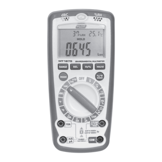
3. Panel Description ROOM 1. Humidity & Temperature - Humidity Sensor and Semiconductor sensor inside for indoor. 2. LCD display - 4000 count LCD display. 3. Function switch 4. V / Hz% / Ω / CAP / °C input jack 5. -
Page 5: Features
12. Ambient Temp °C/°F - Press the ambient temperature button to display temperature on screen in °C or °F 13. MODE button - To select AC or DC measurement when in A, mA, uA, and Ω, , ranges. 14. RANGE button - To select AC or DC measurement when in Voltage, Ω... -
Page 6: Specifications
5. Specifications 5.1. General Specifications Display: 4000 counts LCD display with function of Lux, °C, % and dB indication. Polarity: Automatic, ( - ) negative polarity indication. Over-range: “OL” mark indication. Low battery indication: The “ ” is displayed when the battery voltage drops below the operating level. -
Page 7: Temperature/Humidity
5.4. Temperature/Humidity Function Range Resolution Accuracy -20°C to 750°C 1°C ±(3% + 5 digits) Temperature Type-K -4°F to 1382°F 1°F ±(3% + 9 digits) Input Impedance: 10MΩ Overload Protection: 250V DC or AC RMS for 400mV ranges and 250V DC or 250V AC RMS for other ranges. - Page 8 Function Range Accuracy Resolution DC Current 400.0uA 0.1uA ±(1% ± 2 digits) (Auto-Ranging for ±(1% ± 2 digits) 4000uA uA and mA) ±(1.2% ± 2 digits) 400.0mA 100uA 10mA ±(2% ± 5 digits) Overload Protection: 500mA/660V and 10A/600V Fuse Maximum Input: 400mA DC or 400mA AC RMS on uA/mA ranges, 10A DC or AC RMS on 10A range.
-
Page 9: Operating Instructions
Function Range Accuracy Resolution Frequency 5.000Hz 0.001Hz (Auto-ranging) 50.00Hz 0.01Hz 500.0Hz 0.1Hz ±(1.2% ± 3 digits) 5.000kHz 50.00kHz 10Hz 500.0kHz 100Hz 10.00MHz 1kHz ±(1.5% ± 4 digits) Sensitivity: >0.5V RMS while ≤1MHz, Sensitivity: >3V RMS while >1MHz Input Protection: 250V DC or 250V AC RMS Function Range Diode Test... -
Page 10: Measuring Light
6.3. Measuring Light • Set the function switch to the “Lux” scale and set the range to desired (“Lux” or “x10 Lux”) range. • Move the meter to face the photo detector to a light source in a horizontal position. •... -
Page 11: Measuring Temperature
• Store Indoors Stairs Corridor 150 to 200 Show window, Packing table 750 to 1,500 Forefront of show window 1500 to 3,000 • Hospital Sickroom, Warehouse 100 to 200 Medical Examination/Operating room 300 to 750 Emergency Treatment 750 to 1,500 •... -
Page 12: Measuring Ac Voltage
6.6. Measuring AC Voltage • Insert the black test lead banana to the COM jack and red test lead banana to the “V / Hz% / Ω / CAP / °C“ jack. • Set the function switch to the AC ranges to be used and connect test leads across the source or load under measurement. -
Page 13: Measuring Capacitance
• For current measurements up to 10A AC, set the function switch to the yellow10A position and insert the red test lead banana plug into the 10A jack. • Press the MODE button to indicate “AC” on the display. • Remove power from the circuit under test, then open up the circuit at the point where you wish to measure current. -
Page 14: Measuring Diode
• Insert the red test lead banana plug into the “V / Hz% / Ω / CAP / °C” jack. • Indicate “OL” “MΩ” on the display. • Touch the test probe tips across the circuit or part under test. It is best to disconnect one side of the part under test so the rest of the circuit will not interfere with the resistance reading. - Page 15 7. Maintenance Battery and Fuse Replacement If the sign “ ” appears on the LCD display, it indicates that the battery should be replaced. Remove screws on the back cover and open the case. Replace the exhausted battery with new batteries. Fuses rarely need replacement and blow almost always as a result of the operator’s error.
- Page 16 MAJOR TECH (PTY) LTD South Africa Australia www.major-tech.com www.majortech.com.au sales@major-tech.com info@majortech.com.au...
Need help?
Do you have a question about the MT1875 and is the answer not in the manual?
Questions and answers