Table of Contents
Advertisement
Quick Links
Advertisement
Table of Contents

Related Manuals for Rockwell Automation Allen-Bradley 1718-CBL65


Summary of Contents for Rockwell Automation Allen-Bradley 1718-CBL65
- Page 1 All manuals and user guides at all-guides.com User Manual Original Instructions 1718 Ex I/O Catalog Numbers 1718-AENTR, 1718-IJ, 1718-OB2, 1718-OB2L, 1718-IBN8, 1718-IBN8B, 1718-IT4B, 1718-IR4B, 1718-IF4HB, 1718-CF4H, 1718-PSDC, 1718-A20, 1718-A10, 1718-CBL65, 1718-CBL3, 1718-ARM...
-
Page 2: Important User Information
If this equipment is used in a manner not specified by the manufacturer, the protection provided by the equipment may be impaired. In no event will Rockwell Automation, Inc. be responsible or liable for indirect or consequential damages resulting from the use or application of this equipment. -
Page 3: Table Of Contents
Ambient Conditions ......... . 34 Rockwell Automation Publication 1718-UM001A-EN-E - December 2019... - Page 4 Code Number Details ......... 47 Rockwell Automation Publication 1718-UM001A-EN-E - December 2019...
-
Page 5: Who Should Use This Manual
For Release Notes and other publications specific to your module, search the catalog number of the module. To order paper copies of technical documentation, contact your local Allen- Bradley distributor or Rockwell Automation sales representative. Rockwell Automation Publication 1718-UM001A-EN-E - December 2019... - Page 6 All manuals and user guides at all-guides.com Preface Notes: Rockwell Automation Publication 1718-UM001A-EN-E - December 2019...
-
Page 7: Introduction
This manual sets out how to work with the hardware. Refer to the software manual for the gateway and the I/O modules for information on the configuration of the gateway and the I/O modules. Rockwell Automation Publication 1718-UM001A-EN-E - December 2019... -
Page 8: 1718 Ex I/O Components
Ex I/O Empty Slot Cover 1718 Ex I/O Components 1718 Ex I/O Components Overview See the following graphic and table for the descriptions of different 1718 Ex I/O components: Figure 1 - 1718 Ex I/O Components Overview Rockwell Automation Publication 1718-UM001A-EN-E - December 2019... -
Page 9: Field Units
Plastic enclosure Glass fiber reinforced polyester offers a high level of mechanical protection for both onshore and offshore plants. Figure 2 - Field unit with plastic enclosure partially without cover and modules Rockwell Automation Publication 1718-UM001A-EN-E - December 2019... -
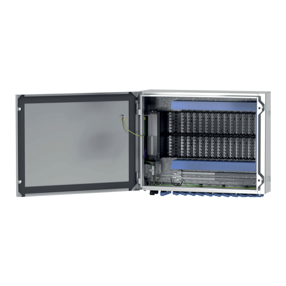
Page 10: Stainless Steel Enclosure
The backplane supplies the modules with energy and provides internal wiring. Any I/O module can be inserted into any I/O slot, enabling a mixture of I/O functions in one field unit. Power supplies, adapters/gateways, and bus Rockwell Automation Publication 1718-UM001A-EN-E - December 2019... -
Page 11: Design And Dimensions
• Redundant configuration with slots for 2 gateways/adapters, 2 bus termination modules, 2 power supplies • Slots for max. 20 narrow or 10 wide I/O modules • For PROFIBUS DP, MODBUS RTU, MODBUS TCP, Ethernet Rockwell Automation Publication 1718-UM001A-EN-E - December 2019... - Page 12 • Redundant configuration with slots for 2 adapters, 2 bus termination modules, 2 power supplies • Slots for max. 10 narrow or 5 wide I/O modules • For PROFIBUS DP, MODBUS RTU, MODBUS TCP, Ethernet Rockwell Automation Publication 1718-UM001A-EN-E - December 2019...
-
Page 13: I/O Modules
The status of each channel is displayed using an LED. This gives your technician clear information about the status of the field device directly on the device itself. For more information about the status LEDs, please refer to the respective datasheets for the modules. Rockwell Automation Publication 1718-UM001A-EN-E - December 2019... -
Page 14: Design And Dimensions Of The Modules
LEDs on the front that display the device status. The I/O modules have connections on the front to which the relevant field devices are connected. On the back of the I/O modules there is a coding pin Rockwell Automation Publication 1718-UM001A-EN-E - December 2019... -
Page 15: Adapter
In addition, the device status is displayed using the four LEDs below the touch screen. Rockwell Automation Publication 1718-UM001A-EN-E - December 2019... -
Page 16: Bus Termination Modules
I/O modules, and tightened using the side screws. Terminal blocks can come in the form of screw terminals, front screw terminals, or spring terminals. Use blue terminal blocks for intrinsically safe circuits. Rockwell Automation Publication 1718-UM001A-EN-E - December 2019... - Page 17 Protective covers (IP30) are used to protect the wiring to the terminal blocks, so that no bare, conductive parts are exposed. Use black protective covers for non-intrinsically safe circuits that comply with type of protection Ex e. Rockwell Automation Publication 1718-UM001A-EN-E - December 2019...
- Page 18 Coding pins provide a unique assignment between I/O modules and terminal blocks or the associated field devices. To do this, the coding pins are pushed into the grooves provided in the front sockets of the I/O modules. This Rockwell Automation Publication 1718-UM001A-EN-E - December 2019...
- Page 19 Using the additional resistor network, the electronics can distinguish between a closed switch and a short circuit. To do this, the resistor network must be positioned directly on the field device. Rockwell Automation Publication 1718-UM001A-EN-E - December 2019...
-
Page 20: Cordsets
There are two types of cordsets for gateways. One with a wired connection in Ex-i protection and one with M12 threaded plugs in Ex-e protection. The gateway cordset provides a local connection between two gateways. If two Rockwell Automation Publication 1718-UM001A-EN-E - December 2019... - Page 21 All manuals and user guides at all-guides.com Product Specifications Chapter 1 gateways are used in a redundant system, they must be connected using a cordset via the front M12 socket or plug to enable internal data exchange. Rockwell Automation Publication 1718-UM001A-EN-E - December 2019...
- Page 22 All manuals and user guides at all-guides.com Chapter 1 Product Specifications Notes: Rockwell Automation Publication 1718-UM001A-EN-E - December 2019...
-
Page 23: Testing Physical Connection Right To The End Of The Segment
5. Activate the terminator on the bus connector for the master. 6. Plug the bus connector back into the master. Rockwell Automation Publication 1718-UM001A-EN-E - December 2019... -
Page 24: Testing Physical 1718 Ex I/O Unit Connection
For the purposes of fault analysis, we recommend using a bus monitor that is capable of passively monitoring data telegrams on the fieldbus. Rockwell Automation Publication 1718-UM001A-EN-E - December 2019... - Page 25 All manuals and user guides at all-guides.com Commissioning Chapter Preface Rockwell Automation Publication 1718-UM001A-EN-E - December 2019...
- Page 26 All manuals and user guides at all-guides.com Chapter Preface Commissioning Rockwell Automation Publication 1718-UM001A-EN-E - December 2019...
- Page 27 In addition, you can read off basic information about supply and communication from the LEDs on the I/O modules and adapters. For more information about the LEDs, refer to the data sheets for the I/O modules and adapters used. Rockwell Automation Publication 1718-UM001A-EN-E - December 2019...
- Page 28 All manuals and user guides at all-guides.com Chapter Preface Operation Rockwell Automation Publication 1718-UM001A-EN-E - December 2019...
-
Page 29: Communication Errors
• Check that the plug-in jumpers are set correctly. possible Multiple I/O modules fail simultaneously • Check that the power supply is working properly. • Check that the base backplane and the extension backplane are wired correctly. Rockwell Automation Publication 1718-UM001A-EN-E - December 2019... - Page 30 I/O module reported to be faulty • Check that the correct I/O module is plugged in. • Check that the green LED on the I/O module is lit and that the I/O module is correctly plugged in. Rockwell Automation Publication 1718-UM001A-EN-E - December 2019...
- Page 31 All manuals and user guides at all-guides.com Troubleshoot Your Module Appendix A Rockwell Automation Publication 1718-UM001A-EN-E - December 2019...
- Page 32 All manuals and user guides at all-guides.com Appendix A Troubleshoot Your Module Rockwell Automation Publication 1718-UM001A-EN-E - December 2019...
-
Page 33: Power Supply
• Dual-width I/O modules: 32 x 100 x 103 mm (1.26 x 3.94 x 4.06 in.) • Adapters and power supplies: 32 x 100 x 103 mm (1.26 x 3.94 x 4.06 in.) Rockwell Automation Publication 1718-UM001A-EN-E - December 2019... -
Page 34: Ambient Conditions
-20...+60 °C (-4 ...+140 °F) Storage temperature: -25...+85 °C (-13 °F ... +185 °F) Relative humidity: 95% noncondensing Designed for pollution degree 2 Damaging gas: Designed for operation in environmental conditions according to ISA-S71.04-1985, severity level G3 Rockwell Automation Publication 1718-UM001A-EN-E - December 2019... - Page 35 • Common practice commands provide access to functions that can be carried out by many devices. • Device specific commands provide access to functions that can be unique to a particular device. Rockwell Automation Publication 1718-UM001A-EN-E - December 2019...
-
Page 36: Message Structure
This way, two masters (if they are present) take turns at communicating with the slave devices. Typical message lengths and delays allow two transactions per second. Burst Mode Burst mode is not supported by the 1719 HART analog modules. Rockwell Automation Publication 1718-UM001A-EN-E - December 2019... -
Page 37: Response Code And Field Device Status
Transmitter-specific command error In Write-protect mode Update Failed - Update In Progress - Set to Nearest Possible Value Applied Process Too High - Lower Range Value Too High - Not In Fixed Current Mode Rockwell Automation Publication 1718-UM001A-EN-E - December 2019... - Page 38 Software revision Hardware revision Device function flags 9…11 Device ID number Read primary PV units code variable 1…4 Primary variable Read current and None 0…3 Current (mA) percent of range 4…7 Primary variable % Rockwell Automation Publication 1718-UM001A-EN-E - December 2019...
- Page 39 (2) Bit 6 = multisensor device. Bit 1 = EEPROM control required. Bit 2 = protocol bridge device. (3) Truncated after last supported variable. (4) 24 bits each LSB…MSB refers to A0 #1…24. (5) Sint [] Rockwell Automation Publication 1718-UM001A-EN-E - December 2019...
- Page 40 Write PV sensor 0…2 Sensor serial number As in command serial number Read dynamic None PV transmitter variable code variable SV transmitter variable code assignments TV transmitter variable code FV transmitter variable code Rockwell Automation Publication 1718-UM001A-EN-E - December 2019...
- Page 41 PV 1…4 PV analog output level analog output PV units code 6…9 Primary variable SV units code 11…14 Secondary variable TV units 16…19 Tertiary variable FV units code 21…24 Fourth variable Rockwell Automation Publication 1718-UM001A-EN-E - December 2019...
- Page 42 Analog output transfer function code Read analog Analog output number Analog output number code output endpoint code Analog output endpoint units code values 2…5 Analog output upper endpoint value 6…9 Analog output lower endpoint value Rockwell Automation Publication 1718-UM001A-EN-E - December 2019...
-
Page 43: Hart Pv, Sv, Tv, And Fv Status
TV, FV dynamic variables that are automatically collected in the 1719-IF4HB and 1719-CF4H Input Tag. This mapping is part of the field device configuration, usually performed via a handheld configurator or asset management system, such as FactoryTalk AssetCentre or Endress+Hauser FieldCare system. Rockwell Automation Publication 1718-UM001A-EN-E - December 2019... - Page 44 00001101 Not Limited 00001110 Not Limited 00001111 Not Limited 00010000 Low Limited 00010001 Low Limited 00010010 Low Limited 00010011 Low Limited 00010100 Low Limited 00010101 Low Limited 00010110 Low Limited 00010111 Low Limited Rockwell Automation Publication 1718-UM001A-EN-E - December 2019...
- Page 45 If the PV, SV, TV, FV are being collected without communication errors, the value is set to 16#C0, indicating Good, Not Limited. Otherwise, the value is set to 0, indicating Bad, Not Limited, no specific information available. Rockwell Automation Publication 1718-UM001A-EN-E - December 2019...
- Page 46 All manuals and user guides at all-guides.com Appendix C Additional HART Protocol Information Notes: Rockwell Automation Publication 1718-UM001A-EN-E - December 2019...
-
Page 47: Code Number Details
Rockwell Automation Publication 1718-UM001A-EN-E - December 2019... - Page 48 Rockwell Automation Publication 1718-UM001A-EN-E - December 2019...
- Page 49 API °API percent solids per weight % solid/weight percent solids per volume % solid/volume degrees balling degrees balling proof per volume proof/volume proof per mass proof/mass bushels bushel cubic yards cubic yd Rockwell Automation Publication 1718-UM001A-EN-E - December 2019...
- Page 50 (15.6 °C or 60 °F) micrograms per liter micrograms/L micrograms per cubic meter micrograms/cubic m percent consistency % consistency volume percent volume % percent steam quality % steam quality feet in sixteenths ft in sixteenths Rockwell Automation Publication 1718-UM001A-EN-E - December 2019...
- Page 51 4 °C (39.2 °F) inH2O (4 °C or 39.2 °F) millimeters of water at 4 °C (39.2 °F) mmH2O (4 °C or 39.2 °F) Rockwell Automation Publication 1718-UM001A-EN-E - December 2019...
- Page 52 All manuals and user guides at all-guides.com Appendix D Engineering Unit Code Numbers Notes: Rockwell Automation Publication 1718-UM001A-EN-E - December 2019...
- Page 53 All manuals and user guides at all-guides.com...
- Page 54 How Are We Doing? form at http://literature.rockwellautomation.com/idc/groups/literature/documents/du/ra-du002_-en-e.pdf. Rockwell Automation maintains current product environmental information on its website at http://www.rockwellautomation.com/rockwellautomation/about-us/sustainability-ethics/product-environmental-compliance.page. Allen-Bradley, CompactLogix, ControlLogix, FLEX 5000, Integrated Architecture, Logix5000, Logix 5000, Rockwell Automation, Rockwell Software, Studio 5000, and Studio 5000 Logix Designer are trademarks of Rockwell Automation, Inc.
Need help?
Do you have a question about the Allen-Bradley 1718-CBL65 and is the answer not in the manual?
Questions and answers