Table of Contents
Advertisement
Quick Links
Installation Instructions
Original Instructions
1718 Ex I/O
Catalog Numbers: 1718-AENTR, 1718-IJ, 1718-OB2, 1718-OB2L, 1718-IBN8, 1718-
IBN8B, 1718-IT4B, 1718-IR4B, 1718-IF4HB, 1718-CF4H, 1718-PSDC, 1718-A20, 1718-A10,
1718-CBL3, 1718-ARM
Topic
Insert and Remove Modules
Page
2
4
6
8
9
9
15
11
12
15
19
22
24
26
31
Advertisement
Table of Contents

Subscribe to Our Youtube Channel
Related Manuals for Rockwell Automation Allen-Bradley 1718-AENTR


Summary of Contents for Rockwell Automation Allen-Bradley 1718-AENTR
-
Page 1: Table Of Contents
Installation Instructions Original Instructions 1718 Ex I/O Catalog Numbers: 1718-AENTR, 1718-IJ, 1718-OB2, 1718-OB2L, 1718-IBN8, 1718- IBN8B, 1718-IT4B, 1718-IR4B, 1718-IF4HB, 1718-CF4H, 1718-PSDC, 1718-A20, 1718-A10, 1718-CBL3, 1718-ARM Topic Page Important User Information European Hazardous Location Approval IEC Hazardous Location Approval Enclosures Chassis Mount the Chassis Insert and Remove Modules Wire the Chassis Ex e Terminals... -
Page 2: Important User Information
In no event will Rockwell Automation®, Inc. be responsible or liable for indirect or consequential damages resulting from the use or application of this equipment. - Page 3 • Use a static-safe workstation, if available. • Store the equipment in appropriate static-safe packaging when not in use. At the end of its life, this equipment should be collected separately from any unsorted municipal waste. Rockwell Automation Publication 1718-IN001A-EN-E - June 2020...
-
Page 4: European Hazardous Location Approval
• Field connections and mounting: the type of protection is "II 2(1) G Ex db eb q [ia Ga] IIC Gb" and "II (1) D [Ex ia Da] IIIC", comply to Standards EN 60079-0:2012/A11:2013, EN 60079-1:2014, EN 60079-5:2015, EN 60079-7:2015 and EN 60079-11:2012. Certificate Presafe 19 ATEX 14054 U. Rockwell Automation Publication 1718-IN001A-EN-E - June 2020... - Page 5 • Mounting: the type of protection is " II 2 G Ex db eb mb IIC T4", comply to Standards EN 60079- 0:2009, EN 60079-1:2007, EN 60079-7:2007, EN 60079-18:2009 Certificate Presafe BVS 11 ATEX E 041 X. Rockwell Automation Publication 1718-IN001A-EN-E - June 2020...
-
Page 6: Iec Hazardous Location Approval
• Field connections and mounting: the type of protection is "Ex db eb q [ia Ga] IIC Gb" and "[Ex ia Da] IIIC", comply to Standards IEC 60079-0:2011 IEC 60079-1:2014 IEC 60079-5:2015 IEC 60079- 7:2015 IEC 60079-11:2011 Certificate IECEx PRE 19.0009U. Rockwell Automation Publication 1718-IN001A-EN-E - June 2020... - Page 7 • Secure any external connections that mate to this equipment by using screws, sliding latches, threaded connectors, or other means provided with this product. • Do not disconnect equipment unless power has been removed or the area is known to be nonhazardous. Rockwell Automation Publication 1718-IN001A-EN-E - June 2020...
-
Page 8: Enclosures
1718 Ex I/O Enclosures Rockwell Automation partners with Pepperl + Fuchs for enclosure solutions. For more details on the enclosures from our partners, see publication 1718- PP002. WARNING: Errors during installation can cause life-threatening injuries and significant property damage. • Ensure the installation is performed only by sufficiently trained and qualified personnel. -
Page 9: Chassis
Use only accessories and devices that are approved for use in the respective environment. Wire the power supply and the network cables using the 1718-CBL3 cable. The 1718-CBL3 cable connects the base and extension chassis. The chassis Ex e Rockwell Automation Publication 1718-IN001A-EN-E - June 2020... - Page 10 Observe respective approvals for explosion protection. For more information on selecting the appropriate chassis, see the Chassis section in the 1718 Ex I/O User Manual, publication 1718-UM001. Chassis Ex e Terminals Clear protective cover Rockwell Automation Publication 1718-IN001A-EN-E - June 2020...
-
Page 11: Wire The Chassis Ex E Terminals
Ex e Terminal Assignment – Chassis Connection with 1718-CBL3 cable Base Chassis Terminal Base Chassis 1718-CBL3 Wire Color Extension Chassis Terminal Blue Black Violet Pink Red/blue Yellow Green Brown White Brown/green Yellow/brown Gray Rockwell Automation Publication 1718-IN001A-EN-E - June 2020... -
Page 12: Output Deactivation Feature
The safe state is defined as de-energized field circuit. • To use the output shutdown of I/O modules in slots 1 to 10, replace plug-in jumper 18 and 19 with an external voltage-free contact. Rockwell Automation Publication 1718-IN001A-EN-E - June 2020... - Page 13 SELV/PELV and not exceed a U (common mode) of 60V. Ex e Terminal Assignment – Power and Ground Connection Terminal Icon Terminal Description Function Number Equipotential Bonding of the hazardous area Power supply 1 Power supply 2 Rockwell Automation Publication 1718-IN001A-EN-E - June 2020...
- Page 14 If the power dissipation is not specified in the technical data, the power dissipation is calculated using the value of the power consumption. Rockwell Automation Publication 1718-IN001A-EN-E - June 2020...
-
Page 15: Insert And Remove Modules
• If the connector pins are bent or damaged, replace the module with an intact original module. • You are not permitted to repair modules with bent connector pins yourself. Bent Connector Pins Rockwell Automation Publication 1718-IN001A-EN-E - June 2020... - Page 16 You can stick the labels between the female connectors of the chassis. The label strips should be no thicker than normal paper so that the I/O modules engage properly at all times. Rockwell Automation Publication 1718-IN001A-EN-E - June 2020...
- Page 17 1. Align the connecting guides on the module to the two sets of latch hooks of an available slot on the chassis. 2. Push the module gently into the slot until you hear two clicks. Rockwell Automation Publication 1718-IN001A-EN-E - June 2020...
- Page 18 3. While still holding the removal latches, pull the module away from the chassis. The removal latch and sheath section lifts away from the chassis connector pins. Rockwell Automation Publication 1718-IN001A-EN-E - June 2020...
-
Page 19: Field Wiring
I/O modules are wired differently depending on the type. Overview of connections Designation Description Modules with intrinsically safe Field connections can be made to the I/O modules using screw terminals, front screw circuits and front sockets terminals, or spring terminals. Rockwell Automation Publication 1718-IN001A-EN-E - June 2020... - Page 20 Core cross-section for wire end ferrules with plastic sleeve 0.5 mm according to IEC 60228 Class 5 and 6 Core cross-section for wire end ferrules without plastic sleeve 0.5…1.5 mm according to IEC 60228 Class 5 and 6 Rockwell Automation Publication 1718-IN001A-EN-E - June 2020...
- Page 21 Front screw terminals or spring terminals are ideal for future expansion or for replacement of individual field connections, since the terminal can remain in the front socket of the I/O module during wiring. Rockwell Automation Publication 1718-IN001A-EN-E - June 2020...
-
Page 22: Install Field Wiring For Intrinsically Safe Circuits
2. Note the permissible core cross section of the conductor. We recommend that you do not exceed a conductor cross section of: 0.5 mm (20 AWG) for 1718-IBN8 0.75 mm (18 AWG) for all other modules. Rockwell Automation Publication 1718-IN001A-EN-E - June 2020... - Page 23 1. To code the front socket of an I/O module, insert one or more coding pins into the corresponding grooves on the front socket. (1) Not applicable for 1718-IBN8 Ex I/O 8 Point Digital Input module. Rockwell Automation Publication 1718-IN001A-EN-E - June 2020...
-
Page 24: Line Fault Detection
• 1719-IJ frequency counter module If the input is used for direction detection, the input must be connected to a resistor circuit. The rotation direction input is ignored for devices without rotation direction detection. 10 KΩ 2.2 KΩ Rockwell Automation Publication 1718-IN001A-EN-E - June 2020... - Page 25 4. In the configuration software, set the measuring input of the I/O module to 2-wire measurement with Pt100 sensor. 5. Enter the measured resistance in the Line resistance field. The maximum permissible line resistance is 50 Ω. Rockwell Automation Publication 1718-IN001A-EN-E - June 2020...
-
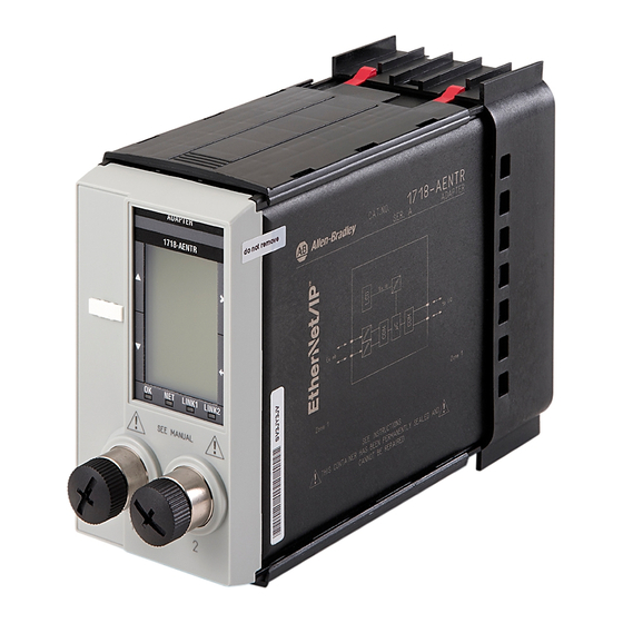
Page 26: Ethernet/Ip Connection
The adapter is connected to the Ethernet network using the two Ethernet interfaces on the front. Mechanically, this occurs through an M12 plug connection according to IEC 61076-2-101:2012. Three basic connection scenarios are shown below: Rockwell Automation Publication 1718-IN001A-EN-E - June 2020... - Page 27 Cable shielding: Connection to the equipotential bonding of the hazardous area (system earth) PB (Protective Bonding according to IEC 61140:2016) Elementary Safety Considerations System earth: • The enclosure is connected to the equipotential bonding PB of the hazardous area (system earth). Rockwell Automation Publication 1718-IN001A-EN-E - June 2020...
- Page 28 • The shielding must be connected to the same “PA” at both ends of the wire (or PE in the safe area). • Do not exceed the maximum cable length of 100 m. Rockwell Automation Publication 1718-IN001A-EN-E - June 2020...
- Page 29 This means that the induced noise is practically canceled out, while in parallel cores the noise is active across the entire area. A shielding keeps interfering noise away from the communication path. Rockwell Automation Publication 1718-IN001A-EN-E - June 2020...
- Page 30 For sound results, ground one end of the cable if the cable is laid on a grounded metal cable support. To reduce interference and ensure that only small areas are Rockwell Automation Publication 1718-IN001A-EN-E - June 2020...
-
Page 31: System Expansion
3. Change to galvanically isolated circuits. System Expansion Add I/O modules Transfer input or output data to a slot that was previously empty, by adding an I/O-module. To do this, you need to modify the adapter configuration. Rockwell Automation Publication 1718-IN001A-EN-E - June 2020... - Page 32 Rockwell Otomasyon Ticaret A.Ş. Kar Plaza İş Merkezi E Blok Kat:6 34752 İçerenkÖy, İstanbul, Tel: +90 (216) 5698400 EEE YÖnetmeliğine Uygundur Allen-Bradley, expanding human possibility, FactoryTalk, Rockwell Automation, and TechConnect are trademarks of Rockwell Automation, Inc. EtherNet/IP is a trademark of ODVA, Inc.
Need help?
Do you have a question about the Allen-Bradley 1718-AENTR and is the answer not in the manual?
Questions and answers