
Related Manuals for Rockwell Automation Allen-Bradley 1732E-IT4IM12R


Summary of Contents for Rockwell Automation Allen-Bradley 1732E-IT4IM12R
- Page 1 ArmorBlock Dual-port EtherNet/IP 4-point Isolated Thermocouple and RTD Input Modules Catalog Numbers 1732E-IT4IM12R, 1732E-IR4IM12R User Manual Original Instructions...
- Page 2 If this equipment is used in a manner not specified by the manufacturer, the protection provided by the equipment may be impaired. In no event will Rockwell Automation, Inc. be responsible or liable for indirect or consequential damages resulting from the use or application of this equipment.
-
Page 3: Table Of Contents
Internet Protocol Tab ........32 Rockwell Automation Publication 1732E-UM004B-EN-P - October 2021... - Page 4 ............67 Rockwell Automation Publication 1732E-UM004B-EN-P - October 2021...
-
Page 5: Preface
A manual on how to install, configure and maintain linear and Device-level Ring (DLR) networks EtherNet/IP Device Level Ring Application Technique, publication ENET-AT007 using Rockwell Automation EtherNet/IP devices with embedded switch technology. Describes how to configure and use EtherNet/IP devices to communicate on the EtherNet/IP EtherNet/IP Network Devices User Manual, ENET-UM006 network. - Page 6 Ethernet Reference Manual, ENET-RM002 Describes basic Ethernet concepts, infrastructure components, and infrastructure features. Provides guidance on how to conduct security assessments, implement Rockwell Automation System Security Design Guidelines Reference Manual, SECURE-RM001 products in a secure system, harden the control system, manage user access, and dispose of equipment.
-
Page 7: Module Features
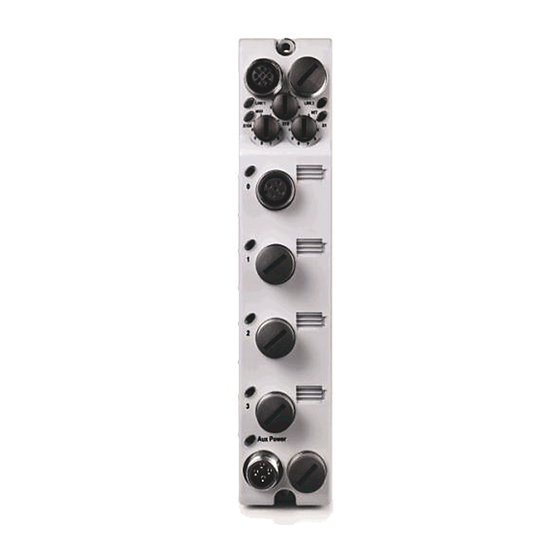
Node address switches • Connectors (two EtherNet/IP D-code M12 connectors, two micro-style Power in/out connectors, four I/O M12 connectors) • Status indicators (Link, I/O, Module, Network, and Auxiliary power status indicators) • Functional earth ground Rockwell Automation Publication 1732E-UM004B-EN-P - October 2021... -
Page 8: Types Of Modules
Description Connector Connector 24V DC power, 4-Point Isolated Thermocouple 1732E-IT4IM12R Input, Dual-Port EtherNet/IP Module Dual 4-pin M12 style, Dual D-code M12 A-coded 24V DC power, 4-Point Isolated RTD Input, 1732E-IR4IM12R Dual-Port EtherNet/IP Module Rockwell Automation Publication 1732E-UM004B-EN-P - October 2021... -
Page 9: Hardware/Software Compatibility
TR4CJC-DM as shown in the next diagram. (1) The Allen-Bradley 871A-TS4CJC-DM or 871A-TR4CJC-DM terminal chamber has an embedded thermistor, which facilitates thermocouple-based temperature measurement. The thermistor types supported are Thermometrics MF65F302V/W, or DC95F302V/W. Rockwell Automation Publication 1732E-UM004B-EN-P - October 2021... -
Page 10: Rtd Sensor Types
The compensation circuit depends on an outside module jumper to connect the third wire if the compensating lead wire is not available (that is, if a 2-wire RTD is connected to the I/O connector). Rockwell Automation Publication 1732E-UM004B-EN-P - October 2021... -
Page 11: Module Alarms
It is specified in units of milliseconds. A digital filter value of 0 disables the filter. To learn how to configure digital filters, see page Rockwell Automation Publication 1732E-UM004B-EN-P - October 2021... - Page 12 Chapter 1 Overview of the ArmorBlock Thermocouple and RTD Input Modules Notes: Rockwell Automation Publication 1732E-UM004B-EN-P - October 2021...
-
Page 13: Overview
Valid settings range from 001…254. 5. Replace switch dust caps. Make sure not to over tighten. 6. Reapply power. 7. Record IP address on product label found on the side of enclosure. Rockwell Automation Publication 1732E-UM004B-EN-P - October 2021... - Page 14 Disables the web server. Cycle power to the module for the setting to take effect. When you apply power, the module LED flashes red to indicate that the web server is disabled. Rockwell Automation Publication 1732E-UM004B-EN-P - October 2021...
-
Page 15: Mount The Module
(1.26) (0.71) Install the mounting base as follows: 1. Lay out the required points as shown above in the drilling dimension drawing. 2. Drill the necessary holes for #6 (M3) pan head screws. Rockwell Automation Publication 1732E-UM004B-EN-P - October 2021... -
Page 16: Wire The Module
Pin 4 Pin 5 No connect Shell No connect (1) Only 4 of the 5 pins are active. The center pin (5) is internally tied to signal ground to minimize external noise pickup. Rockwell Automation Publication 1732E-UM004B-EN-P - October 2021... - Page 17 Both modules require two 24V DC (nominal) supplies. These supplies are called the Module Power and the Auxiliary Power. The Module power supplies the microprocessor, Ethernet, and the module I/O, while Auxiliary power is daisychained through the module. Rockwell Automation Publication 1732E-UM004B-EN-P - October 2021...
- Page 18 Use grounding type bushings and jumper wires. IMPORTANT The 1732E-IR4IM12R and the 1732E-IT4IM12R modules require a functional earth connection to the top earth grounding tab in order to mitigate network surge, ESD, or EMC events. Rockwell Automation Publication 1732E-UM004B-EN-P - October 2021...
-
Page 19: Introduction
Module Definition properties. These are distinctly covered in this chapter. Set Up the Hardware In this example, a ControlLogix® chassis contains the 1756-L85E processor in slot 1. The ArmorBlock module is mounted remotely. Rockwell Automation Publication 1732E-UM004B-EN-P - October 2021... -
Page 20: Create The Example Application
Be sure you configured your communication driver (for example, AB_ETH-1 or AB-ETHIP-1) in RSLinx software. Create the Perform the following steps to create the example application: Example Application 1. From the File menu, select New. Rockwell Automation Publication 1732E-UM004B-EN-P - October 2021... -
Page 21: Configure Your I/O Module
1. Add the 1732E-IT4IM12R or 1732E-IR4IM12R module as a child of the 1756- L85E Controller. 2. Accept the default configuration or change it to specific configuration for the module. 3. Edit configuration for a module when changes are needed. Rockwell Automation Publication 1732E-UM004B-EN-P - October 2021... -
Page 22: Add The Module To Your Project
To look for the 1732E-IT4IM12R module in the list, you can type the catalog number in the search box or use the filters. To do so, click Clear Filters and check Analog in the Module Type Category Filters. Rockwell Automation Publication 1732E-UM004B-EN-P - October 2021... -
Page 23: Download The Program To Your Controller
After you write configuration for your module, the module does not use this Your Controller configuration until you download it to the owner-controller. The download transfers the entire program to the controller, overwriting any existing program. Rockwell Automation Publication 1732E-UM004B-EN-P - October 2021... -
Page 24: Edit Your Module Configuration
The editing process begins on the main page of the Studio 5000 Logix Designer application. 1. On the I/O Configuration tree for your project, right-click the name of your module. Rockwell Automation Publication 1732E-UM004B-EN-P - October 2021... -
Page 25: General Tab
The exact level of emulation required is product and revision specific. Rockwell Automation Publication 1732E-UM004B-EN-P - October 2021... -
Page 26: Connection Tab
(RPI), inhibit a module, and set a connection fault when the controller is in Run mode. The RPI defines the maximum time period between I/O data to be transferred to the owner-controller without causing a fault. Rockwell Automation Publication 1732E-UM004B-EN-P - October 2021... -
Page 27: Configuration Tab For 1732E-Ir4Im12R
1732E-IR4IM12R module. You can only set the sample rate/notch filter of the 1732E-IR4IM12R IMPORTANT module for all four channels at once. Individual channel setting is not available. Rockwell Automation Publication 1732E-UM004B-EN-P - October 2021... - Page 28 °F -3280 15620 °C -2000 6300 200 Ω Pt 385 °F -3280 11660 °C -2000 6500 100 Ω Pt 3916 °F -3280 12020 °C -2000 6500 200 Ω Pt 3916 °F -3280 12020 Rockwell Automation Publication 1732E-UM004B-EN-P - October 2021...
-
Page 29: Configuration Tab For 1732E-It4Im12R
The supported temperature resolution is 0.1 °C/0.1°F. Configuration Tab for 1732E-IT4IM12R 1. Choose from the options on the Configuration tab. Configuration tab Field Description Channel Indicates the four input channels 0…3. Rockwell Automation Publication 1732E-UM004B-EN-P - October 2021... - Page 30 (the thermistor) is used. Valid values are Cold Junction Compensation Mode Channel Independent, or Average Selected. Cold Junction Compensation (CJC) Mode on page 41 to learn more about the CJC modes. Rockwell Automation Publication 1732E-UM004B-EN-P - October 2021...
-
Page 31: Alarm Configuration Tab
Select a value so that any value out of range in this field Set from High causes a profile validation error. This value also appears in -32,768...+32,767 the HI slider on this dialog. Rockwell Automation Publication 1732E-UM004B-EN-P - October 2021... -
Page 32: Internet Protocol Tab
IP settings, specify the IP address in the Physical Module IP Address field. 2. On the other fields (Domain Name, Host Name, Primary DNS Server Address, Secondary DNS Server Address), specify the corresponding parameter. Click Set and then click OK. Rockwell Automation Publication 1732E-UM004B-EN-P - October 2021... -
Page 33: Port Configuration Tab
Calibration is available on a per-channel basis for both Thermocouple and RTD modules. Calibration points for the Thermocouple module is 0 and 78.125 mV for each channel. For the RTD module, calibration endpoints are dependent on the sensor type configured for each channel. Rockwell Automation Publication 1732E-UM004B-EN-P - October 2021... -
Page 34: Status And Monitoring Tabs
Although each dialog box maintains importance during online monitoring, some of the tabs, such as the Module Info and Network, are blank during the initial module configuration. You can refer to these tabs Rockwell Automation Publication 1732E-UM004B-EN-P - October 2021... - Page 35 Chapter 3 Configure Your Thermocouple and RTD Input Modules Check the status of your module using these tabs. Rockwell Automation Publication 1732E-UM004B-EN-P - October 2021...
- Page 36 Chapter 3 Configure Your Thermocouple and RTD Input Modules Notes: Rockwell Automation Publication 1732E-UM004B-EN-P - October 2021...
-
Page 37: Overview
The software configurable features available are: • sensor type • temperature units reported in °C, °F • cold junction compensation enable, mode, and offset (for 1732E-IT4IM12R) • Sample Rate/Notch Filter • Digital Filter Rockwell Automation Publication 1732E-UM004B-EN-P - October 2021... -
Page 38: Configurable Options And Their Effect On The Channels
Ni/14.2%Cr/1.4%Si vs. Ni/ -270…1300 °C (-454…2372 °F) -4.345…47.513 4.4%Si/0.1%Mg Pt/13%Rh vs. Pt -50…1768 °C (-58…3214.4 °F) -0.226…21.101 Pt/10%Rh vs. Pt -50…1768 °C (-58…3214.4 °F) -0.236…18.693 Cu vs. Cu/Ni -270…400 °C (-454…752 °F) -6.258…20.872 Rockwell Automation Publication 1732E-UM004B-EN-P - October 2021... -
Page 39: Temperature Units
500 Hz The higher sample rate settings of 250 Hz and 500 Hz are for applications where the temperature resolution of the channels only needs to be in the order of 1…2 °C. Rockwell Automation Publication 1732E-UM004B-EN-P - October 2021... -
Page 40: Digital Filter
When this parameter is set for a channel, compensation is derived from one or more thermistors attached to the module. If not set (disabled), compensation will come from a user-entered value (CJC Offset). Rockwell Automation Publication 1732E-UM004B-EN-P - October 2021... -
Page 41: Data Tables
Bit 1 Bit 0 Byte Cold Junction Mode 5…7 Reserved (Ignore) 8…9 Channel 0 Low Engineering 10…11 Channel 0 High Engineering Channel 0 Disable Alarms Channel 0 Enable Alarm Latch Channel 0 Notch Filter Rockwell Automation Publication 1732E-UM004B-EN-P - October 2021... - Page 42 Channel 2 Low Low Alarm 72…73 Channel 2 High High Alarm Channel 2 Temperature Units Channel 2 Cold Junction Enable 76…77 Channel 2 Cold Junction Offset 78…79 Reserved (Ignore) 80…81 Channel 3 Low Engineering Rockwell Automation Publication 1732E-UM004B-EN-P - October 2021...
- Page 43 Channel 1 Low Alarm 32…33 Channel 1 High Alarm 34…35 Channel 1 Low Low Alarm 36…37 Channel 1 High High Alarm Channel 1 Enable Alarm Latch Channel 1 Disable Alarms Channel 1 RTD Type Rockwell Automation Publication 1732E-UM004B-EN-P - October 2021...
- Page 44 Bit 0 Byte 0…3 Reserved (must be zero) 4…5 Channel 0 Data 6…7 Channel 1 Data 8…9 Channel 2 Data 10…11 Channel 3 Data Channel 0 Status Channel 1 Status Channel 2 Status Rockwell Automation Publication 1732E-UM004B-EN-P - October 2021...
- Page 45 Bit 0 = Fault; Bit 1 = Calibration; Bit 2 = Low Alarm; Bit 3 = High Alarm; Bit 4 = Low Low Alarm; Bit 5 = High High Alarm; Bit 6 = Underrange; Bit 7 = Overrange Rockwell Automation Publication 1732E-UM004B-EN-P - October 2021...
- Page 46 Chapter 4 Configurable Features for the Thermocouple and RTD Input Modules Notes: Rockwell Automation Publication 1732E-UM004B-EN-P - October 2021...
-
Page 47: Overview
A precision decade resistor box also can be used that meets or exceeds the required accuracy specifications. You are responsible for assuring that the decade box maintains accuracy by periodic calibration. Calibrate the Thermocouple The 1732E-IT4IM12R module only calibrates in millivolts. You can calibrate the Module module to a 0…78.125 mV range. Rockwell Automation Publication 1732E-UM004B-EN-P - October 2021... - Page 48 It informs you that this is dangerous with an active system and there is a mismatch. This message box gives you an option to quit. Help is provided to you more information. Rockwell Automation Publication 1732E-UM004B-EN-P - October 2021...
- Page 49 If calibration is configured to be done In Groups, the High Value dialog box shows all the channels enabled for calibration. 9. From the High Value dialog, click Next to start calibration. The Input Calibration - Results dialog appears. It shows you the results of calibration. Rockwell Automation Publication 1732E-UM004B-EN-P - October 2021...
-
Page 50: Calibrate The Rtd Module
Properties dialog box. See Edit Your Module Configuration on page 1. Click Calibration Tab on the Module Properties dialog box. Choose whether to calibrate each channel one at a time or in groups all at once Rockwell Automation Publication 1732E-UM004B-EN-P - October 2021... - Page 51 (low reference and high reference) of calibration. If calibration is configured to be done In Groups, the Low Value dialog box shows all the channels enabled for calibration. Rockwell Automation Publication 1732E-UM004B-EN-P - October 2021...
- Page 52 This takes you back to steps 6…8. You will have to go through the same cycle of steps for each of the next channels lined up for calibration. 11. After successful calibration on the channel(s), click Finish to close the Calibration Wizard. Rockwell Automation Publication 1732E-UM004B-EN-P - October 2021...
-
Page 53: Interpret Status Indicators
• Auxiliary power status indicator • Individual I/O status indicators for inputs Link 1 status indicator Link 2 status indicator Module status indicator Network status indicator I/O status indicators Auxiliary power status indicator Rockwell Automation Publication 1732E-UM004B-EN-P - October 2021... - Page 54 The input channel is inactive, can be calibrated. Flashing green Channel is calibrating. I/O status Green Normal operation, inputs being scanned. Flashing yellow Thermistor fault. Flashing red Fault. Overrange, underrange, or process alarm is present. Rockwell Automation Publication 1732E-UM004B-EN-P - October 2021...
-
Page 55: Check For Faults
1 s in response to a module communication fault. In this example, a communication fault occurred between the controller and the module, so the controller automatically writes 1 s for all bits in the word. Rockwell Automation Publication 1732E-UM004B-EN-P - October 2021... - Page 56 Appendix A Troubleshoot the Module Notes: Rockwell Automation Publication 1732E-UM004B-EN-P - October 2021...
-
Page 57: Introduction
Log On to the Web Server Navigate the ArmorBlock I/O Introduction Rockwell Automation offers enhanced ArmorBlock I/O for your EtherNet/IP control systems so you can monitor data remotely from web pages. IMPORTANT To reduce the likelihood of exploitation and associated security risk, we recommend that you keep the web server disabled. -
Page 58: Access The Home Page Of The Web Server
From your web browser, enter the IP address of the ArmorBlock I/O module. the Web Server The module displays its home page. Specify the IP address of the module in the Address field. Module home page Rockwell Automation Publication 1732E-UM004B-EN-P - October 2021... -
Page 59: Log On To The Web Server
Click folders to open and close additional levels of information. Click a document to display a web page showing specific information. Rockwell Automation Publication 1732E-UM004B-EN-P - October 2021... -
Page 60: Access Diagnostic Information
You can also view configuration information through the Web Server pages. Information Click Configuration folder. Click the Configuration folder to expand the navigation. You can view and edit Device Identity, Network Configuration and Device Services information. Rockwell Automation Publication 1732E-UM004B-EN-P - October 2021... -
Page 61: Module Tags For 1732E-It4Im12R
Alarms bit indicating the channel’s input is greater than the maximum detectable input signal. I.Ch2Overrange I.Ch3Overrange I.CJData The cold junction sensor temperature in counts where -32,768 counts is 0 °C (32 °F) and 32,767 counts is 86 °C (186 °F). Rockwell Automation Publication 1732E-UM004B-EN-P - October 2021... - Page 62 C.Ch3LLAlarmLimit C.Ch0HHAlarmLimit C.Ch1HHAlarmLimit The high high alarm trigger point. This value causes the Ch<0...3>HHAlarm bit to trigger when the input signal moves C.Ch2HHAlarmLimit above the configured trigger point, in engineering units. C.Ch3HHAlarmLimit Rockwell Automation Publication 1732E-UM004B-EN-P - October 2021...
-
Page 63: Module Tags For 1732E-Ir4Im12R
Alarms bit indicating the channel’s input is greater than the maximum differential input range for the selected sensor BOOL I.Ch2Overrange type. ADC reported data values are invalid with this bit flag set.. I.Ch3Overrange Rockwell Automation Publication 1732E-UM004B-EN-P - October 2021... - Page 64 C.Ch2SensorType Sensor Type on page 38 for list of valid input values. C.Ch3SensorType Ch0TempMode Controls the temperature scale to use on the module. Ch1TempMode SINT 0 = Celsius Ch2TempMode 1 = Fahrenheit Ch3TempMode Rockwell Automation Publication 1732E-UM004B-EN-P - October 2021...
-
Page 65: Access The Module Tags
– this option allows you to add or delete tags but not to change their values When you click Edit Tags or Monitor Tags, you can view and/or edit the tags through the following screen that shows all the tags for your modules: Rockwell Automation Publication 1732E-UM004B-EN-P - October 2021... - Page 66 Appendix C Module Tag Definitions Notes: Rockwell Automation Publication 1732E-UM004B-EN-P - October 2021...
-
Page 67: Index
53 default configuration 21 use 22 default gateway 14 defaults 13 browser requirements DHCP 13 embedded web server 57 diagnostic information 60 Diagnostic Overview 60 digital filter 28 digital filters 11 Rockwell Automation Publication 1732E-UM004B-EN-P - October 2021... - Page 68 58 web server 59 host name 32 Network Address 13 network address 13 network LED 14 node address switches 7 noise transients 11 configure 21 notch filter 28 I/O Configuration tree 24 Rockwell Automation Publication 1732E-UM004B-EN-P - October 2021...
- Page 69 54 web server 57 flashing yellow 54 log in 59 green 54 wiring 16 red 54 status indicators 7 auxiliary power 7 I/O 7 link 7 module 7 network 7 status monitoring 34 Rockwell Automation Publication 1732E-UM004B-EN-P - October 2021...
- Page 70 Index Notes: Rockwell Automation Publication 1732E-UM004B-EN-P - October 2021...
- Page 71 ArmorBlock Dual-port EtherNet/IP 4-point Isolated Thermocouple and RTD Input Modules User Manual Rockwell Automation Publication 1732E-UM004B-EN-P - October 2021...
- Page 72 At the end of life, this equipment should be collected separately from any unsorted municipal waste. Rockwell Automation maintains current product environmental information on its website at rok.auto/pec. Allen-Bradley, ArmorBlock, ControlFLASH, ControlLogix, expanding human possibility, FactoryTalk, Logix 5000, Rockwell Automation, RSLinx, RSLogix 5000, Studio 5000 Logix Designer, and TechConnect are trademarks of Rockwell Automation, Inc.
Need help?
Do you have a question about the Allen-Bradley 1732E-IT4IM12R and is the answer not in the manual?
Questions and answers