Table of Contents
Advertisement
Quick Links
Advertisement
Table of Contents

Related Manuals for Rockwell Automation Allen-Bradley ControlNet Ex Media


Summary of Contents for Rockwell Automation Allen-Bradley ControlNet Ex Media
- Page 1 ControlNet Ex Media 1797-series Planning and Installation Manual...
- Page 2 In no event will Rockwell Automation, Inc. be responsible or liable for indirect or consequential damages resulting from the use or application of this equipment.
-
Page 3: Table Of Contents
Table of Contents Preface What’s in This Chapter ......1-1 Abbreviations and Symbols ......1-2 Common Techniques . - Page 4 Table of Contents Order Components ......2-17 General Planning ......2-17 Plan a Segment .
- Page 5 Table of Contents Appendix B Adjust the Cable Strip Tool What This Appendix Contains ..... . B-1 Calibrate the Cutting Blades......B-1 Reverse and Replace the Cutting Blades .
- Page 6 Table of Contents Publication CNET-IN003A-EN-P - January 2006...
-
Page 7: What's In This Chapter
Preface What’s in This Chapter Use this manual to plan and install a ControlNet Ex media system. This manual describes the required components of an intrinsically-safe cable system and how to plan for and install these required components. This manual targets the configurion of a ControlNet Ex system. However, since a ControlNet Ex system and a ControlNet system can be linked, it may be necessary to introduce and refer to concepts on the ControlNet side of the network. -
Page 8: Abbreviations And Symbols
Preface Abbreviations and Symbols The following table explains abbreviations and symbols we use in this manual. This Means PVC cable polyvinyl chloride cable FEP cable fluorinated ethylene propylene cable PLC processor Allen-Bradley programmable logic controller network continues (other nodes not shown) Common Techniques We use the following conventions throughout this manual: •... -
Page 9: Overview Of The Controlnet Ex Media System
Chapter Overview of the ControlNet Ex Media System What This Chapter Contains Use this chapter to familiarize yourself with the ControlNet Ex media system. The following table describes what this chapter contains and where to find specific information. For Information On See Page Understand the ControlNet Ex Media System Understand ControlNet Ex Components... -
Page 10: Understand The Controlnet Ex Media System
Overview of the ControlNet Ex Media System Understand the ControlNet The ControlNet Ex media system gives you the flexibility to design a communication network for your particular application. To take full Ex Media System advantage of this flexibility, spend sufficient time when you plan how to install your network before you assemble any of the hardware. - Page 11 Overview of the ControlNet Ex Media System Term Means • Any physical device connecting to the ControlNet Ex or ControlNet media system that Node requires a network address to function on the network • A network may contain a maximum of 99 nodes •...
-
Page 12: Understand Controlnet Ex Components
Overview of the ControlNet Ex Media System Understand ControlNet Ex The ControlNet Ex media system is comprised of these components: Components • Nodes • Taps • Trunk cable • Cable connectors • Terminators • Segments • Fiber repeater hubs (option) •... -
Page 13: Trunk Cable
Overview of the ControlNet Ex Media System There are four styles of taps available with: • T or Y placement of BNC connectors 40955 T-tap Y-tap • Straight or right-angle connector on the drop media Straight Right-angle 40956 Use only intrinsically-safe taps in a ControlNet Ex ATTENTION media system. -
Page 14: Cable Connectors
Trunk Cable 40957 Optional Connectors Rockwell Automation also offers optional cable connectors for use in your network configuration. See page 2-8 for available connectors. Trunk Terminator A 75 Ω terminator (cat. no. 1797-XT) must be installed on the tap at each end of a segment. -
Page 15: Tap Terminator
Overview of the ControlNet Ex Media System Tap Terminator A tap terminator (cat. no. 1797-TCAP) is available to terminate unused taps. Segment 1797-TCAP Trunk Cable 40959 Use only intrinsically-safe tap terminators in a ATTENTION ControlNet Ex media system. Intrinsically-safe tap terminators are marked “CNet Tap Trm.”... -
Page 16: Network
Overview of the ControlNet Ex Media System hubs and cable length total are limited depending on your network topology. You can have a maximum of 5 repeaters in series. Safe Area Hazardous Area Coax Segment Coax Segment Trunk Cable Coax (1786) Fiber Hubs Ex (1797) Fiber Hubs 41327 Fiber Segment... -
Page 17: Controlnet Ex System Installation Requirements
Overview of the ControlNet Ex Media System Two insulator kits are available: • Catalog number 1797-BOOT provides standard BNC trunk cable insulators. • Catalog number 1797-INS provides a variety of the preformed boots and insulators used with the ControlNet Ex system products. -
Page 18: Certified Equivalent Controlnet Ex System Components
Component Catalog Number Source Coax Trunk Cable 1797-RG6 Rockwell Automation 3092IS Belden Wire & Cable Co. 3092A with blue jacket Belden Wire & Cable Co. Belden Wire & Cable 1189A may be used, but with functional loss of communication distance or nodes. -
Page 19: Ul, Cul I/O Entity Parameters And Requirements
Overview of the ControlNet Ex Media System 1-11 UL, cUL I/O Entity Parameters and Requirements For more information on UL and cUL installation requirements, refer to publication 1797-RM001, FLEX Ex System Certification Reference Manual. Terminals (mA) Groups (µF) (µH) Male Bus Connector The entity concept allows interconnection of intrinsically-safe apparatus with associated apparatus not specifically examined in combination as a system when the approved values of V... -
Page 20: European Community Directive Compliance
1-12 Overview of the ControlNet Ex Media System If fiber optic cable is provided with a metal shield, it must be connected to a dedicated intrinsic safety ground in the intrinsically-safe location and isolated in the non-intrinsically-safe location or be connected to a ground in the hazardous location and isolated in the intrinsically-safe location. -
Page 21: Ex Directive
Overview of the ControlNet Ex Media System 1-13 Ex Directive The ControlNet Ex System is tested to meet the Council Directive 94/9 EC (ATEX 100a) Equipment and Protective Systems Intended for Use in Potentially Explosive Atmospheres by applying the following standards: •... - Page 22 1-14 Overview of the ControlNet Ex Media System Notes: Publication CNET-IN003A-EN-P - January 2006...
-
Page 23: Plan A Controlnet Ex Media System
Chapter Plan a ControlNet Ex Media System What This Chapter Contains Read this chapter to determine your network requirements. See Page Determine How Many Taps You Need Connect Programming Devices in Safe Areas Coax Cable Type Fiber Media Type Determine Trunk Cable Section Lengths Estimate Fiber Media Lengths Determine How Many Trunk Terminators You Need Determine What Type of Connectors You Need... -
Page 24: Determine How Many Taps You Need
Plan a ControlNet Ex Media System Determine How Many Taps The number of taps you need depends on the number of devices you want to connect to the network. You need a tap for each node, You Need repeater, or fiber hub on the network. If you plan to add nodes later, you should consider ordering and installing the cable and connectors for these additional nodes when you install the initial network. -
Page 25: Connect Programming Devices In Safe Areas
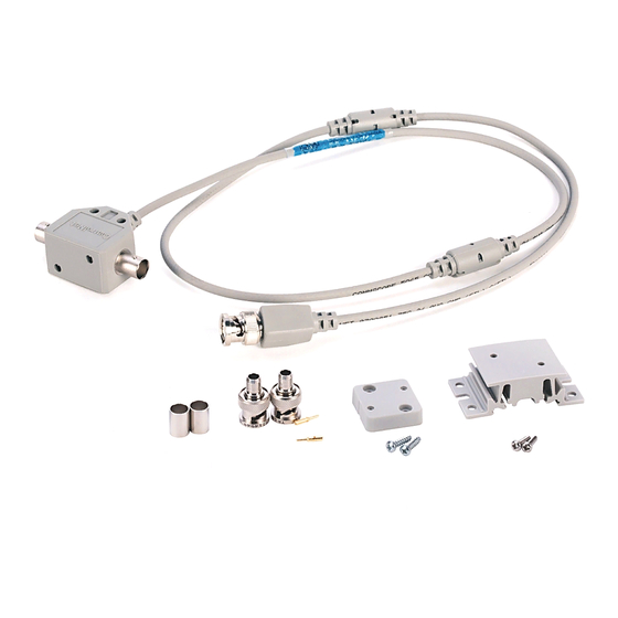
Plan a ControlNet Ex Media System These tap kits are available (dust caps not shown): Right-Angle Y-Tap Straight T-Tap Straight Y-Tap Right-Angle T-tap 41330 1797-TPS 1797-TPR 1797-TPYR 1797-TPYS Connect Programming Connect programming devices in safe areas to the ControlNet cable system through a 1784-KTCX15 communication card. -
Page 26: Fiber Media Type
Plan a ControlNet Ex Media System Fiber Media Type Fiber media type specifications are listed below. • Fiber type 62.5/125 µ • Connector type ST (plastic or ceramic) • Operating wavelength 1300 nm • Optical power budge 13.3 dB You should install all fiber for your ControlNet Ex cable system in accordance with the regulations contained in applicable country codes, state codes, and applicable municipal codes (for example, National Electric Code). - Page 27 Plan a ControlNet Ex Media System requirement. The maximum allowable total length of a segment is 1,000 m (3,280 ft) with two taps connected. Each additional tap decreases the maximum length of the segment by 16.3 m (53.4 ft). The maximum number of taps allowed on a segment is 48 with a maximum length of 250 m (820 ft).
-
Page 28: Determine Trunk Cable Section Length When You Use A Flex Ex Redundant Controlnet Barrier Module
Plan a ControlNet Ex Media System If your segment requires 3 taps using 1786-RG6 EXAMPLE cable, the maximum segment length is: ([20.29 db - 3*.32 db] / 5.99 db] * 304) (19.33 db / 5.99 db) * 304 = 982 m (3227 ft) The total trunk cable length or number of taps can IMPORTANT be increased by installing a repeater hub on the... -
Page 29: Estimate Fiber Media Lengths
Plan a ControlNet Ex Media System 500 m (1640 ft) 250 m (820 ft) Number of Taps With One FLEX Ex Redundant ControlNet Barrier Module Estimate Fiber Media The maximum length of a fiber media section for the 1797-RPFM module is dependent on the quality of the fiber, number of splices, Lengths and the number of connectors. -
Page 30: Determine What Type Of Connectors You Need
Plan a ControlNet Ex Media System After you have determined the number of segments in your network, multiply this number by two to determine how many terminators you need for your network. To comply with intrinsic safety standards, be sure to IMPORTANT cover the exposed metal with the intrinsically-safe insulator provided with each terminator. - Page 31 Plan a ControlNet Ex Media System Cable Enters and Exits From the Side In This Example, ControlNet Ex Panel Wall Cable: Isolated-bulkhead Connectors • Enters and exits the panel Bullet Connector enclosure from the side using isolated-bulkhead connectors Barrel Connector •...
-
Page 32: Use Redundant Media In A Hazardous Area
2-10 Plan a ControlNet Ex Media System Use Redundant Media in a You can run a second trunk cable between your ControlNet Ex nodes for redundant media. With redundant media, nodes send signals on Hazardous Area two separate segments. The receiving node compares the quality of the two signals and accepts the better signal to permit use of the best signal. - Page 33 Plan a ControlNet Ex Media System 2-11 • Install the cable system so that the trunk cables at any physical device location can be easily identified and labeled with the appropriate icon or letter. Each redundant ControlNet Ex device is labeled so you can connect it to the corresponding trunk cable.
- Page 34 2-12 Plan a ControlNet Ex Media System • Avoid connecting a single node’s redundant trunk cable connections on different segments; this will cause erratic operation. Safe Area Hazardous Area 1786 Fiber 1797 Fiber Segment 1 Repeater Hubs Repeater Hubs Allen-Bradley Allen-Bradley Q UALITY 1797 - RPA...
-
Page 35: Application Considerations
Plan a ControlNet Ex Media System 2-13 Application Considerations The following guidelines coincide with the guidelines for the installation of electrical equipment to minimize electrical noise inputs to controllers from external sources contained in IEEE standard 518-1982. When planning your cable system keep these installation considerations in mind. -
Page 36: General Wiring Guidelines
2-14 Plan a ControlNet Ex Media System General Wiring Guidelines Follow these guidelines with regard to noise coupling. Following intrinsic safety requirements should prevent most or all of these situations from occurring. These guidelines are provided as a general reference for wiring. •... -
Page 37: Ferrite Beads
Plan a ControlNet Ex Media System 2-15 When you run cable inside an enclosure, route conductors external to all raceways in the same enclosure, or in a raceway separate from Category-1 conductors. Route Your Cable At Least From Noise Sources of This Strength 0.08 m (3 in.) Category 1 conductors of less than 20 A 0.15 m (6 in.) -
Page 38: Add Ferrite Beads
2-16 Plan a ControlNet Ex Media System Add Ferrite Beads Wrap the IS power input cable two turns around the ferrite bead before connecting the terminal block to the adapter. Five ferrite beads come with the adapter. Four are short and identical. -
Page 39: Order Components
Plan a ControlNet Ex Media System 2-17 Order Components Now that you are ready to begin ordering components, use these guidelines to help you select components. General Planning The ControlNet Ex cable system is isolated from earth and must be protected from inadvertent ground connections. -
Page 40: Plan Your Network
2-18 Plan a ControlNet Ex Media System Plan Your Network Refer to this list when you plan your network. • Maximum of 99 nodes (excluding fiber repeater hubs) • Fiber repeater hubs require a tap but are not counted as nodes (they are included in the number of devices allowed per segment [48]) •... - Page 41 Plan a ControlNet Ex Media System 2-19 Item Cat. No. Guidelines Required Quantity Coax Tool Kit 1786-CTK Use the tool kit to create your trunk cable to your specifications. You will need to double your quantities when ordering components for a redundant cable system. The connector kit may be shipped with two ferrules.
-
Page 42: What Is Next
2-20 Plan a ControlNet Ex Media System What Is Next? After you gather all of the parts for your ControlNet Ex media system, you are ready to go to Chapter 3 to begin the installation of your network. Publication CNET-IN003A-EN-P - January 2006... -
Page 43: What This Chapter Contains
Chapter Install a ControlNet Ex Media System What This Chapter Contains Follow the instructions in this chapter to install your ControlNet Ex media system. See Page Install the Trunk Cable Mount the Taps Specifications Install Fiber Hubs Install Cable Connectors 3-13 Connect Cable Sections 3-25... -
Page 44: Wire Inside Enclosures
Install a ControlNet Ex Media System Wire Inside Enclosures When the RG-6 type coax cable is not being pulled through conduit, follow these specifications. For This Coax Cable The Bend Radius Should Not Exceed 38.1 mm (1.5 in.) Tap drop-cable 25.4 mm (1.0 in.) The 1797-EXMK Cable Marking kit is available for clearly marking drop cables and trunk cables as intrinsically-safe. -
Page 45: Mount The Taps
Install a ControlNet Ex Media System Do not allow any metal portions of the tap, such as ATTENTION the universal mounting bracket screws or connectors, to contact any conductive material. This contact could cause noise on the network. Also be certain all exposed metal is covered by either the intrinsically-safe insulators or tape having a 500V dielectric rating. - Page 46 Install a ControlNet Ex Media System Mount a Tap with a Universal Mounting Bracket 1. Align the universal mounting bracket with the mounting holes on the tap. 2. Use the screws provided with the tap to attach the tap to the universal mounting bracket.
- Page 47 Install a ControlNet Ex Media System 3. Mount the tap and bracket assembly to a DIN rail or another mounting surface. DIN Mounting Rail Another Mounting Surface Universal Mounting Bracket Universal Mounting Bracket Use four screws to attach the universal mounting bracket to another mounting surface.
-
Page 48: Specifications
Install a ControlNet Ex Media System Mount a Tap Through the Body Holes A suitable fixture (mounting surface) can be conductive or grounded because the mounting holes are electrically isolated. Mount the tap to a suitable fixture by using a tie wrap, or screws and flat washers. -
Page 49: Installation In Zone 1
Install a ControlNet Ex Media System Installation in Zone 1 The 1797-RPA and 1797-RPFM modules must not be exposed to the environment. You must install these modules in a metal enclosure. This repeater hub has a protection factor of IP20. These modules cannot be used in a hazardous ATTENTION environment after they have been exposed to... -
Page 50: Select A Fiber Repeater Hub Mounting Location
Install a ControlNet Ex Media System Ex Directive This product is tested to meet the Council Directive 94/9 EC (ATEX 100a) Equipment and Protective Systems Intended for Use in Potentially Explosive Atmospheres by applying the following standards: • EN50014:1992, Electrical Apparatus for Potentially Explosive Atmospheres •... -
Page 51: Mount The Fiber Repeater Hub
Install a ControlNet Ex Media System Mount the Fiber Repeater Hub Follow this procedure to mount the fiber repeater hub. 1. Position the module on a 35 mm x 7.5 mm (1.38 in. x 0.30 in.) DIN rail (A-B part number 199-DR1) at approximately a 30° angle. - Page 52 3-10 Install a ControlNet Ex Media System 4. If the adapter does not snap into position, use a screwdriver or similar device to move the locking tab down while pressing the module flush onto the DIN rail. Release the locking tab to lock the module in place.
-
Page 53: Connect The Fiber Repeater Hub To A Controlnet Ex Network
Install a ControlNet Ex Media System 3-11 Connect the Fiber Repeater Hub to a ControlNet Ex Network 1. Connect to the ControlNet Ex coax network with the drop line of the Ex coax tap to the adapter BNC connector. Intrinsically-safe Insulator 41170 2. - Page 54 3-12 Install a ControlNet Ex Media System 4. Apply +V and -V power from a 1797 power supply to the adapter through a removable terminal block. +V -V +V -V +V -V +V -V 41297 Screw terminals and spring terminals are provided. 5.
-
Page 55: Install Cable Connectors
Install a ControlNet Ex Media System 3-13 Install Cable Connectors After you have mounted the taps, you need to attach cable connectors to the ends of your trunk cable sections. Collect Your Tools To install the cable connectors, we recommend that you use the tools in the ControlNet Coax Toolkit, catalog number 1786-CTK. -
Page 56: Strip The Cable
3-14 Install a ControlNet Ex Media System Strip the Cable When you cut cable sections, make them long enough to route from one tap to the next with sufficient length so that the bend radius is not less than: • 76.2 mm (3 in.) for wiring external to enclosures •... - Page 57 Install a ControlNet Ex Media System 3-15 4. Lock the cable into place by moving the chamber-gauge ring forward until it meets the cable with slight resistance. 20073 This gauge moves two rollers toward the cable and regulates the depth of the cut. The gauge will click as it moves from one gauge to the next.
- Page 58 3-16 Install a ControlNet Ex Media System 6. After you have moved the chamber gauge ring to the last position and turned the strip tool the final time: a. Move the chamber-gauge ring backward to release the strip tool and remove it from the cable. b.
- Page 59 Install a ControlNet Ex Media System 3-17 Be sure to strip the cable to expose these layers of the cable: All Four Shield Layers White Foam Electric Braid/Tape/Braid/Tape Or 1st Tape, If Tape Is Bonded Center Conductor 4.0 mm (0.16 in.) 8.3 mm (0.33 in.) 3.7 mm (0.15 in.) 20076a...
- Page 60 3-18 Install a ControlNet Ex Media System Use the imprint guide on the back of the ControlNet tap or the calibration tool to verify this. T-Tap 3.7 mm 8.3 mm (0.15 in.) (0.33 in.) 4.0 mm (0.16 in.) PVC Cable PVC Cable Only Center Conductor PVC/CL2...
-
Page 61: Test For Electrical Shorts And Continuity Between The Center Conductor And The Shield
Install a ControlNet Ex Media System 3-19 Test for Electrical Shorts and Continuity Between the Center Conductor and the Shield 1. The NetLinx Media Checker (catalog number 1788-MCHKR) is the preferred tool for continuity testing. Attach the connector end of the cable to the port on top of the media checker. Attach the connector end of the cable to the port on top of the media checker. -
Page 62: Attach The Connectors To The Cable
3-20 Install a ControlNet Ex Media System Replace the trunk cable section if problems persist IMPORTANT with the cable after completing these tests. Attach the Connectors to the Cable 1. Push the calibration/flare tool onto the cable and with a slight twisting motion (with sufficient inward pressure) to expand the braid. - Page 63 Install a ControlNet Ex Media System 3-21 2. Place the center pin over the center conductor. Center Conductor center conductor 41889 Sometimes strands of insulation are left on the center conductor. Be certain that the center conductor is clean before you install the center pin. Center Pin center pin Be certain that the center pin slips onto the center...
- Page 64 3-22 Install a ControlNet Ex Media System 3. With the center pin in place, use the crimp tool to crimp the pin into place. The smaller hexagonal crimping notch is for crimping the center pin onto the center connector. 41903 Check for braid strands that could cause a short to center conductor.
- Page 65 Install a ControlNet Ex Media System 3-23 5. Slide the crimp ferrule over the three outer shields and connector base until it meets the shoulder on the connector. 20077e 6. Use the crimp tool to crimp the ferrule. Position the crimp tool on the ferrule as close as possible to where the connector base and ferrule meet.
-
Page 66: Test For Electrical Shorts And Continuity Between The Connector Body And Pin
3-24 Install a ControlNet Ex Media System Test for Electrical Shorts and Continuity Between the Connector Body and Pin 1. Use an ohmmeter or continuity tester to test for a short between the connector body and pin. Attach the connector end of the cable to the port on top of the media checker. -
Page 67: Connect Cable Sections
Install a ControlNet Ex Media System 3-25 3. At the same end of the cable tested in step 1, use an ohmmeter or continuity tester to test for electrical continuity. Attach the connector end of the cable to the port on top of the media checker. - Page 68 3-26 Install a ControlNet Ex Media System 1. Connect one end of the trunk cable section to one of the tap BNC connectors. 20078 2. Slide the intrinsically-safe blue insulator over the BNC connector to cover any exposed metal. 3. Install a 75Ω terminator onto the tap’s other BNC connector. Repeat steps 1 and 2 at the other end of the segment.
-
Page 69: Connect Devices
Install a ControlNet Ex Media System 3-27 Connect Devices After you terminate your segments, connect your devices. To Connect a Fiber repeater hub Page 3-11 ControlNet Ex adapter Procedure below 1. Remove and save the blue dust cap (on the straight or right-angle connector). -
Page 70: Install The 1797-Bcnr Module
FLEX Ex Redundant ControlNet Barrier Module Installation Instructions, publication 1797-5.35. To install the module: 1. Select the appropriate mounting location. 2. Mount the barrier module on Rockwell Automation part number 199-DR1 DIN rail. Publication CNET-IN003A-EN-P - January 2006... - Page 71 Install a ControlNet Ex Media System 3-29 3. Ensure the locking tabs snap into place. Connect the ControlNet Ex side of the barrier IMPORTANT module to either a 1797-ACNR15 FLEX Ex I/O module or a 1797-TCAP FLEX Ex Safe Tap Dummy Load using only ControlNet Ex Taps (such as 1797-TPR, 1797-TPYR, 1797-TPS, or 1797-TPYS).
- Page 72 3-30 Install a ControlNet Ex Media System Notes: Publication CNET-IN003A-EN-P - January 2006...
-
Page 73: What This Appendix Contains
Appendix Mounting Dimensions What This Appendix Use these mounting dimensions to mount your taps, universal mounting brackets, and repeaters. Contains Tap Placement Make copies of these templates as necessary to help you mark placement for your taps. Y-Tap T-Tap 35.66 mm 30.23 mm (1.40 in.) (1.19 in.) -
Page 74: Universal Mounting Bracket
Mounting Dimensions Universal Mounting Bracket 58.42 mm (2.30 in.) 49.53 mm (1.95 in.) 15.47 mm (0.609 in.) 19.05 mm 30.94 mm (0.75 in.) (1.128 in.) 9.53 mm (0.375 in.) 20170-m Publication CNET-IN003A-EN-P - January 2006... -
Page 75: Adjust The Cable Strip Tool
Appendix Adjust the Cable Strip Tool What This Appendix Follow the instructions in this appendix to calibrate the cable strip tool supplied with the ControlNet Coax Toolkit (1786-CTK). Contains Calibrate the Cutting Use the following procedure to calibrate your cable strip tool to cut FEP or PVC cable. - Page 76 Adjust the Cable Strip Tool 6. Retract the handle of the cable strip tool. 7. Remove the calibration tool from the cable strip tool. When you have finished, the blade should make a cut of the following dimensions in your cable. 8.3 mm 3.7 mm 4.0 mm...
-
Page 77: Reverse And Replace The Cutting Blades
Adjust the Cable Strip Tool Reverse and Replace the To reverse or change the cutting blades: Cutting Blades 1. Use a screwdriver to lift the memory blade holder and swing it back. 20182-m 2. Slide the memory blade cartridge out of the strip tool. 20183-m If You Are Go To... - Page 78 Adjust the Cable Strip Tool 30031-m Go to step 5. 4. Align the memory blade cartridge (the side with the raised notches) to the raised area on the inside of the strip tool and slide the new memory blade cartridge in Raised Notch Raised Area 30031a-m...
-
Page 79: Change The Memory Blade Holder
Adjust the Cable Strip Tool Change the Memory Blade You received two memory blade holders with your cable strip tool; one is for PVC-CL2 cable, and the other is for plenum FEP-CL2P cable. Holder You need to install the appropriate memory blade holder for the type of cable you are stripping (PVC or FEP). - Page 80 Adjust the Cable Strip Tool Notes: Publication CNET-IN003A-EN-P - January 2006...
- Page 81 Appendix Protect Your System Against Electrostatic Discharge Protect the system against electrostatic charge. Post a sign near this module: Attention: Avoid electrostatic charge. For your convenience, we provide some signs you can cut out below. Post these labels or something similar beside each module to protect the system against electrostatic charge.
- Page 82 Protect Your System Against Electrostatic Discharge Notes: Publication CNET-IN003A-EN-P - January 2006...
- Page 83 Index 2-10 redundant media 1-2, 1-7, 2-8 repeater abbreviations and symbols 1-7, 2-17 segment about this manual 3-14 stripping trunk cable 2-13 application considerations 2-15 surge suppression 1-2, 1-4, 2-2, 2-18 mounting dimensions 3-25 terminating segments barrel connector 2-18 terminator 1-6, 2-8 BNC cable connectors 1-3, 2-7...
- Page 84 Index changing the memory blade holder support 3-19 NetLinx Media Checker questions or comments about manual node technical product assistance 2-15 surge suppression 3-19 ohmmeter 2-17 ordering components 1-2, 1-4, 2-18 determine number needed mounting programming terminals to a universal mounting bracket ways to connect to a ControlNet link using the body holes publications...
- Page 85 ___No, there is no need to contact me ___Yes, please call me ___Yes, please email me at _______________________ ___Yes, please contact me via _____________________ Return this form to: Rockwell Automation Technical Communications, 1 Allen-Bradley Dr., Mayfield Hts., OH 44124-9705 Fax: 440-646-3525 Email: RADocumentComments@ra.rockwell.com Publication CIG-CO521C-EN-P- May 2003...
- Page 86 PLEASE FASTEN HERE (DO NOT STAPLE) Other Comments PLEASE FOLD HERE NO POSTAGE NECESSARY IF MAILED IN THE UNITED STATES BUSINESS REPLY MAIL FIRST-CLASS MAIL PERMIT NO. 18235 CLEVELAND OH POSTAGE WILL BE PAID BY THE ADDRESSEE 1 ALLEN-BRADLEY DR MAYFIELD HEIGHTS OH 44124-9705...
- Page 88 (see phone number above to obtain one) to your distributor in order to complete the return process. Outside United Please contact your local Rockwell Automation representative for States return procedure. Publication CNET-IN003A-EN-P - January 2006 PN 957208-04 Copyright © 2006 Rockwell Automation, Inc. All rights reserved. Printed in the U.S.A.
Need help?
Do you have a question about the Allen-Bradley ControlNet Ex Media and is the answer not in the manual?
Questions and answers