Advertisement
Installation Instructions
Original Instructions
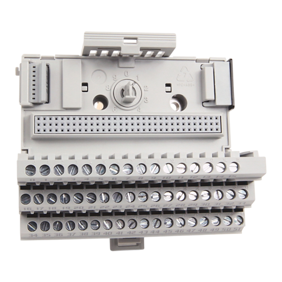
FLEX I/O Grounded Cage Clamp Temperature Terminal Base Unit
Catalog Number 1794-TB3GT
Topic
Summary of Changes
This publication contains the following new or updated information. This list includes substantive updates only and is not intended to reflect all changes.
Topic
Updated template
Updated UK and European Hazardous Location Approvals
Updated IEC Hazardous Location Approvals
Updated Special Conditions for Safe Use
Updated General Specifications
Updated Certifications
Page
1
5
5
7
8
8
Page
throughout
3
4
4
8
9
Advertisement
Table of Contents

Related Manuals for Rockwell Automation Allen-Bradley FLEX


Summary of Contents for Rockwell Automation Allen-Bradley FLEX
-
Page 1: Table Of Contents
Installation Instructions Original Instructions FLEX I/O Grounded Cage Clamp Temperature Terminal Base Unit Catalog Number 1794-TB3GT Topic Page Summary of Changes Overview Mount the Terminal Base Unit on a DIN Rail Wire Connections for the 1794-TB3GT Typical Wiring Guidelines Specifications Summary of Changes This publication contains the following new or updated information. - Page 2 Indien de apparatuur wordt gebruikt op een wijze die niet is gespecificeerd door de fabrikant, dan bestaat het gevaar dat de beveiliging van de apparatuur niet goed werkt. Rockwell Automation Publication 1794-IN133B-EN-P - October 2022...
- Page 3 Secure DIN rail to mounting surface approximately every 200 mm (7.8 in.) and use end-anchors appropriately. Be sure to ground the DIN rail properly. See the Industrial Automation Wiring and Grounding Guidelines, Rockwell Automation publication 1770-4.1, for more information.
- Page 4 • This equipment shall be used within its specified ratings defined by Rockwell Automation. • Transient protection shall be provided that is set at a level not exceeding 140% of the peak rated voltage value at the supply terminals to the equipment.
-
Page 5: Overview
Rotate the terminal base onto the DIN rail with the top of the rail hooked under the lip on the rear of the terminal base. Use caution to make sure that the female Flexbus connector does not strike any of the pins in the mating connector. Rockwell Automation Publication 1794-IN133B-EN-P - October 2022... - Page 6 ATTENTION: When using FLEX I/O modules in a high-vibration installation, especially when mounting the DIN rail vertically, use DIN-rail locks (A-B part number 1492-EA35) to prevent accidental separation of the terminal block units. Rockwell Automation Publication 1794-IN133B-EN-P - October 2022...
-
Page 7: Wire Connections For The 1794-Tb3Gt
Supply out - C-50 (+), C-51 (-) ATTENTION: The wiring on this base unit is different from other terminal base units in FLEX I/O. Make certain that connections are correct before applying power. Rockwell Automation Publication 1794-IN133B-EN-P - October 2022... -
Page 8: Typical Wiring Guidelines
IEC 60068-2-1 (Test Ad, Operating Cold), IEC 60068-2-2 (Test Bd, Operating Dry Heat), Temperature, operating IEC 60068-2-14 (Test Nb, Operating Thermal Shock): -20…+70 °C (-4…+158 °F) Temperature, surrounding air, max 70 °C (158 °F) Rockwell Automation Publication 1794-IN133B-EN-P - October 2022... - Page 9 A = Mounting hole dimensions for optional mounting kit B = DIN rail C = Operating temperature 25.4 (1.0) below each module when mounted in any position Measure here for horizontal position. must not exceed 55 °C (131 °F) Rockwell Automation Publication 1794-IN133B-EN-P - October 2022...
- Page 10 Rockwell Otomasyon Ticaret A.Ş. Kar Plaza İş Merkezi E Blok Kat:6 34752 İçerenköy, İstanbul, Tel: +90 (216) 5698400 EEE Yönetmeliğine Uygundur Allen-Bradley, expanding human possibility, FactoryTalk, FLEX, Rockwell Automation, and TechConnect are trademarks of Rockwell Automation, Inc. Trademarks not belonging to Rockwell Automation are property of their respective companies.
Need help?
Do you have a question about the Allen-Bradley FLEX and is the answer not in the manual?
Questions and answers