
Subscribe to Our Youtube Channel
Related Manuals for Sensia CALDON SVM 289Ci


Summary of Contents for Sensia CALDON SVM 289Ci
- Page 1 CALDON SVM 289Ci Self-Verifying Ultrasonic Meter with G3 Transmitter User Manual MA23102, Rev.
- Page 2 Read user instructions carefully and visually inspect the equipment to become familiar with the device before installing, operating, or maintaining it. Equipment should be installed, operated, serviced, and maintained only by qualified personnel. Sensia assumes no responsibility for consequences arising from the use of this material.
- Page 3 Sensia. In addition, covers, page headers, custom graphics, icons, and other design elements may be service marks, trademarks, and/or trade names of Sensia and may not be copied, imitated, or used, in whole or in part, without the express prior written permission of Sensia.
-
Page 4: Table Of Contents
Publisher Notes CALDON SVM 289Ci Table of Contents Section 1: Introduction ....................... 8 1.1 Equipment Description 1.1.1 SVM 289Ci Meter Body ......................... 8 1.1.2 G3 Transmitter ..........................9 1.2 Model Numbers 1.2.1 Meter Body Model Number ......................11 1.2.2 Transmitter Model Number ......................12 1.2.3 Transmitter Specifications ...................... - Page 5 CALDON SVM 289Ci Publisher Notes 4.2.2 Conversion to Standard Conditions ..................... 32 Section 5: Operations ....................... 34 5.1 Definitions 5.2 Normal Operating Conditions 5.3 Display LEDs 5.4 Display 5.5 Alarm Conditions Section 6: Maintenance ......................39 6.1 Introduction 6.2 General Inspections and Preventative Maintenance Procedures 6.2.1 Electronic Enclosure Inspection ....................
- Page 6 Publisher Notes CALDON SVM 289Ci Figure 2.3—Hoist rings with a lifting bar above the electronics unit allow for uniform lifting...... 18 Figure 2.4—SVM 289Ci installation recommendations ................19 Figure 3.1—Fully assembled transmitter ....................21 Figure 3.2—User terminations, rear view ....................21 Figure 3.3—DC power terminations ......................
- Page 7 CALDON SVM 289Ci Publisher Notes TABLES Table 1.1 Standard K-Factors ........................10 Table 1.2 SVM 289 Transmitter Specifications ................... 13 Table 2.1 Hoist Ring Rated Weights and Part Numbers ................15 Table 3.1 Distance Required from Power Source ..................20 Table 3.2 Power Terminations –...
-
Page 8: Section 1: Introduction
Section 1: Introduction CALDON SVM 289Ci Section 1: Introduction 1.1 EQUIPMENT DESCRIPTION The CALDON SVMError! Bookmark not defined.Error! Bookmark not defined. 289Ci ultrasonic flowmeter is a highly sophisticated bidirectional flow measurement system that employs ultrasonic transit time to measure volumetric flow rate and evaluate the uncertainty in the measurement result. Its advanced signal and data processing are designed to provide robust, high accuracy measurement and unique self-verification capabilities. -
Page 9: G3 Transmitter
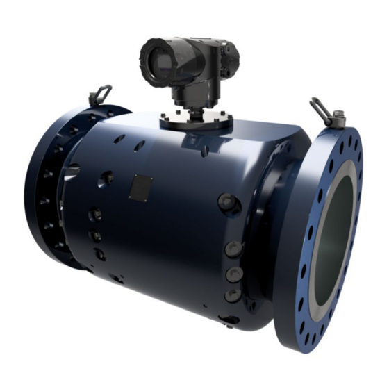
CALDON SVM 289Ci Section 1: Introduction Figure 1.1—Example of meter body and transmitter assembly 1.1.2 G3 TRANSMITTER The transmitter houses the display that provides readouts of flow data including flow rate, total flow volume, fluid properties, analog input data, alarm indication, fault detection, and diagnostic information. -
Page 10: Table 1.1 Standard K-Factors
Section 1: Introduction CALDON SVM 289Ci Four digital outputs • Status − Standard volume pulse outputs − The standard K-factors used to configure transmitters at the factory are listed in Table 1.1. The user may optionally configure the K-factor to meet individual needs. Refer to the meter display or Modbus register for the actual K-factor in use. -
Page 11: Model Numbers
CALDON SVM 289Ci Section 1: Introduction 1.2 MODEL NUMBERS 1.2.1 METER BODY MODEL NUMBER The meter body model number defines construction and features of the meter body. From the model number, a user can identify and verify the component type, meter size, piping thickness, construction material, flange rating/style, and enclosure type. -
Page 12: Transmitter Model Number
Section 1: Introduction CALDON SVM 289Ci 1.2.2 TRANSMITTER MODEL NUMBER The transmitter model number includes information that defines construction and features of the transmitter. MODEL NUMBER CODE: G3MFFFCCPSEXYZ MATERIAL A, ALUMINUM S, STAINLESS STEEL FREQUENCY FFF = BBS FOR A BROADBAND DESIGN... -
Page 13: Transmitter Specifications
Meter body RTD is standard Environment Requirements Storage Temperature -58°F (-50°C) to 185°F (85°C) Operating Temperature -58°F (-50°C) to 158°F (70°C) Altitude Up to 5000 meters for DC applications, 2000 meters for AC applications (Contact Sensia for applications at higher elevations) -
Page 14: Meter Markings
Section 1: Introduction CALDON SVM 289Ci The intended use of this transmitter is a permanently connected installation, Equipment Class II, Pollution Degree 2, Continuous operation. 1.2.4 METER MARKINGS Figure 1.2—Meter body approvals nameplate example Figure 1.3—Meter body serial number nameplate example... -
Page 15: Section 2: Meter Body Installation
If the rings appear damaged or corroded, DO NOT USE. 2.1.1 HOIST RING INSTALLATION Use only Sensia swivel hoist rings (ordered separately; see Table 2.1) in the meter body end flanges. DO NOT USE the following: Eyebolts •... -
Page 16: Sling Attachment
Section 2: Meter Body Installation CALDON SVM 289Ci 1. Before installing hoist rings, refer to your company’s hoisting and rigging standards. If no such company standards exist, refer to the Department of Energy (DOE) STD-1090-2011(Hoisting and Rigging Standard). Additional information can be found in OSHA 29 CFR 1926.251 (Rigging Equipment for Material Handling) and 1926.552 (Material Hoists, Personnel Hoists, and Elevators). -
Page 17: Figure 2.2-Proper Sling Attachment
CALDON SVM 289Ci Section 2: Meter Body Installation WARNING Failure to properly stabilize and support the meter body during installation or removal could allow the meter to shift or roll, posing a hazard that may result in equipment damage or serious injury, up to and including death. -
Page 18: Meter Installation
Section 2: Meter Body Installation CALDON SVM 289Ci Figure 2.3—Hoist rings with a lifting bar above the electronics unit allow for uniform lifting. CAUTION To avoid damaging the swivel hoist rings, never use cables, hooks, or chains to lift the meter body. -
Page 19: Figure 2.4-Svm 289Ci Installation Recommendations
CALDON SVM 289Ci Section 2: Meter Body Installation Downstream of the meter there should be a straight length of at least 3 pipe diameters prior to − any bends, tees, reducers, expanders or valves etc. − In uni-directional applications temperature elements and pressure connections should be located downstream of the meter. -
Page 20: Section 3: Transmitter Connections
Section 3: Transmitter Connections CALDON SVM 289Ci Section 3: Transmitter Connections CAUTION The physical properties, configuration settings, and calibration of the meter body are pre- programmed into the transmitter; therefore, the meter body and transmitter are manufactured as a matched set and must be installed as a pair. Failure to install transmitters and meter bodies as matched sets can result in erroneous flow measurements. -
Page 21: Figure 3.1-Fully Assembled Transmitter
CALDON SVM 289Ci Section 3: Transmitter Connections Figure 3.1—Fully assembled transmitter The four conduit entries at the rear of the transmitter are for user connections. A hazardous area conduit seal is required within 2 inches (5 cm) of the device on every entry used. Unused entries must have plugs installed to be wrench tight with at least five threads fully engaged for a ¾... -
Page 22: Wiring Instructions
Section 3: Transmitter Connections CALDON SVM 289Ci 3.2 WIRING INSTRUCTIONS 3.2.1 POWER TERMINATIONS (TERMINAL BLOCK 1) TB1 contains the power terminations, described below in Table 3.2. The schematics for the power terminations are shown in Figure 3.3 and Figure 3.4, and earth ground terminations are shown in Figure 3.5, page 23.. -
Page 23: User 1 And User 2 Inputs/Outputs
CALDON SVM 289Ci Section 3: Transmitter Connections Figure 3.5—Power terminations (TB1 has terminals 1 and 2 only; safety earth/ground shown in two places) 3.2.2 USER 1 AND USER 2 INPUTS/OUTPUTS There are two groups of inputs/outputs in this transmitter. The groups are organized as User 1 and User 2. -
Page 24: Analog Outputs (Terminal Block 2)
Section 3: Transmitter Connections CALDON SVM 289Ci 3.2.4 ANALOG OUTPUTS (TERMINAL BLOCK 2) TB2 contains the transmitter’s analog outputs, described below in Table 3.4. A typical schematic for the analog outputs, including a depiction of the terminal block 2 configuration, is shown below in Figure 3.7. -
Page 25: Grounding
CALDON SVM 289Ci Section 3: Transmitter Connections Table 3.6 Digital Signals – Recommended 16 to 28 AWG wire Terminal Signal Pulse Description Voltage Description User 1 User 2 Pulse A precedes Pulse B by 90 Pin 12 (+) Pin 28 (+) -
Page 26: Figure 3.9-Earth Points On Transmitter Body (Refer To Table 3.7 For Isolated Ground Connections To Be Made By User)
Section 3: Transmitter Connections CALDON SVM 289Ci Figure 3.9—Earth points on transmitter body (refer to Table 3.7 for isolated ground connections to be made by user) Table 3.7 Ground Connections Recommended 18 AWG wire (internal) and 16 AWG wire (external) -
Page 27: Remote Data Communications
CALDON SVM 289Ci Section 3: Transmitter Connections Note Do not connect the isolated grounds to the earth ground; this defeats the isolation the electronics provide. Generally, User 1 and User 2 grounds are not connected to each other. These grounds are intended for separate users. These isolated grounds should be connected as appropriate to the ground where the signals are going. -
Page 28: Serial Communications
Section 3: Transmitter Connections CALDON SVM 289Ci Figure 3.10—Ethernet locations 3.2.9 SERIAL COMMUNICATIONS The serial communications are half-duplex (two-wire). Terminations for serial communications are provided in Table 3.9. A typical schematic showing the serial communications is shown in Figure 3.11, page 29. -
Page 29: Meter Installation Check-Out
Always return the meter to normal operation following the use of forced outputs in Output Test mode. 8. If the pipe is full of liquid, contact Sensia Technical Support for detailed commissioning steps. 3.3.1 OUTPUT TEST MODE The Output Test mode is used during field testing or verification checks. This output test is best done... -
Page 30: Section 4: Understanding Flow Calculations
Section 4: Understanding Flow Calculations CALDON SVM 289Ci Understanding Flow Calculations Section 4: 4.1 MEASURING FLOW VELOCITIES SVM ultrasonic flowmeters use pairs of transducers to send ultrasonic pulses to one another along measurement paths. The velocity measurement paths are at an angle to the fluid flow. The ultrasonic transit time along a path depends upon the direction of travel and both the speed of sound (SOS) in the fluid and the velocity of the fluid along the path. -
Page 31: Measuring Flow Rate
CALDON SVM 289Ci Section 4: Understanding Flow Calculations ���� ������������ℎ Using this method, the path velocity measurement is independent of the velocity of sound. Consequently, variations in temperature, density, chemical composition, etc. have no direct influence on the velocity results. -
Page 32: Temperature Compensation
Section 4: Understanding Flow Calculations CALDON SVM 289Ci Figure 4.3— Chordal planes used for the primary velocity (4-chord) and velocity profile verification (5-chord) Paths on the diametric plane are used to calculate a fifth value of axial velocity that is used in combination with the four primary chordal velocity results to compute a 5-chord result for velocity profile verification and uncertainty analysis. - Page 33 CALDON SVM 289Ci Section 4: Understanding Flow Calculations Inputs required for gross to net conversions include: • Gross flow rate • Product temperature • Product pressure The specific gravity used for the gross to net conversions can be either an analog input entered via Modbus registers, or a value that is automatically computed by the SVM.
-
Page 34: Section 5: Operations
Section 5: Operations CALDON SVM 289Ci Section 5: Operations 5.1 DEFINITIONS Chord – Chordal plane in which a path is located, numbered 1 through 5 • Chords 1 to 4 are numbered top to bottom, excluding the diameter. • Chord 5 is the diameter. -
Page 35: Normal Operating Conditions
CALDON SVM 289Ci Section 5: Operations 5.2 NORMAL OPERATING CONDITIONS If the flowmeter is properly installed, the display will begin working when power is supplied to the unit. Two LED indicators— one showing a valid power connection and the other showing the meter is in a “RUN”... - Page 36 Section 5: Operations CALDON SVM 289Ci Table 5.2 Display Screens Display Type Example Content Description Measurement Flow and combined measurement uncertainty viewed in volumetric (m /hr) terms Uncertainty Combined measurement uncertainty viewed in relative (%) terms Alarm Summary Meter K-Factor is displayed.
-
Page 37: Alarm Conditions
CALDON SVM 289Ci Section 5: Operations Table 5.2 Display Screens Display Type Example Content Description Path SOS The transmitter displays and checks the consistency of the sound velocities computed by each path. Software The top row shows analog input measured channels Information (A1, A2, A3, T1). - Page 38 Section 5: Operations CALDON SVM 289Ci 1. The system checks the data quality for ultrasonic paths and evaluates the data against thresholds. Data evaluation is based on signal to noise ratio (SNR), cross-correlation tests, and signal statistics. 2. The transmitter confirms the self-consistency of the sound velocities computed by each path.
-
Page 39: Section 6: Maintenance
3. Remove access covers. a. Inspect gaskets. Clean gaskets and mating surfaces on the enclosure with water if they are dirty. b. Contact Sensia if there is any corrosion on the mating surfaces. c. Verify that gaskets compress when the cover is installed. -
Page 40: Transmitter Troubleshooting
Section 6: Maintenance CALDON SVM 289Ci 5. Inspect the display for damage. 6.3 TRANSMITTER TROUBLESHOOTING Perform the following inspections on the transmitter to isolate a problem. WARNING Never open the transmitter or the transducer covers when the instrument is energized. -
Page 41: Iop - Input/Output And Power Supply Board Or Power Fuse Replacement
CALDON SVM 289Ci Section 6: Maintenance Figure 6.1—Transmitter components 6.4.1 IOP – INPUT/OUTPUT AND POWER SUPPLY BOARD OR POWER FUSE REPLACEMENT A metrological seal wire connects the IOP to the CTC. This seal wire must be cut to remove the IOP. -
Page 42: Figure 6.3-Location Of Iop/F25 Fuse
Section 6: Maintenance CALDON SVM 289Ci If any component on the IOP assembly fails (other than the fuse), you must replace the entire assembly as described below, referring to Figure 6.2 for hardware locations. Loosen the 2mm hex set screw on the rear enclosure. Unscrew and remove the rear lid of the enclosure. -
Page 43: Ctc And Display Replacement
CALDON SVM 289Ci Section 6: Maintenance 7. Remove the F25 fuse with tweezers or needle nose pliers and replace it with a new fuse. DC Option: Only use Littelfuse Series part number 0454-005 (5 amp rating) as a replacement −... - Page 44 Section 6: Maintenance CALDON SVM 289Ci WARNING The transmitter has a real time clock that has battery backup. It is recommended to replace the complete circuit board if the battery ever fails. Do not replace the battery alone. It must be replaced with the identical battery and it must never be changed in a hazardous location area.
-
Page 45: Figure 6.5-Sw3 Setting For Use With A 204B169 Iop
CALDON SVM 289Ci Section 6: Maintenance Figure 6.5—SW3 setting for use with a 204B169 IOP 6. Connect the ribbon cable to the back of the CTC card. Gently press the CTC assembly onto the IOP connector. Refer to Figure 6.6 below for a view of the routing path. -
Page 46: Mxr Replacement
Section 6: Maintenance CALDON SVM 289Ci 9. Reattach the display by aligning the connector on the rear of the display board to connector P2 on the CTC. 10. Reinstall the three screws that secure the display board to the CTC. -
Page 47: Figure 6.7-Disassembling The Transmitter To Access The Mxr
CALDON SVM 289Ci Section 6: Maintenance Figure 6.7—Disassembling the transmitter to access the MXR 4. Remove the MXR daughter board as follows. a. Loosen the transducer wires ribbon cables on the MXR daughter board (two connectors) and disconnect both connectors. Push the transducer wires/connectors to the side so that the MXR daughter board can be removed, marking the cables for reassembly. -
Page 48: Transducer Installation
5 through 9, page 43. 6.5 TRANSDUCER INSTALLATION WARNING Do not attempt replacement of a transducer without technical guidance from Sensia. Contact Sensia technical support at https://www.sensiaglobal.com/Technical-Support. WARNING Never open the transmitter when the instrument is energized. Before inspecting components, open the power supply circuit breaker. -
Page 49: Analog Input Verification
Section 6: Maintenance WARNING Never tamper with the transducer housing (shown in Figure 6-10). The housing is pressurized and contains two locking rings to keep the housing in place. Only Sensia technicians may remove these pressure-containing components. Figure 6.10—Transducer housing detail 4. -
Page 50: Analog Output And Pulse Output Verification
Section 6: Maintenance CALDON SVM 289Ci 6.7 ANALOG OUTPUT AND PULSE OUTPUT VERIFICATION The digital output channels consist of an analog output and a pulse output. The current output channel has a 4-20 mA range. The pulse output has a range of 0 to 5V or 0 to 12V. There are no adjustments to be performed for the analog or pulse outputs. -
Page 51: Section 7: Troubleshooting And Diagnostics
Ethernet port. The transmitter’s serial and Ethernet ports use the Modbus protocol. Sensia’s CALDON USM Advisor software allows the user to interface with the transmitter via the serial port or Ethernet port. -
Page 52: Automatic Fault Detection
Section 7: Troubleshooting and Diagnostics CALDON SVM 289Ci For troubleshooting ultrasonic signals, the most frequently used diagnostic parameters are shown below in Table 7.1. Table 7.1 Signal Diagnostics Typical Values for Diagnostic Parameter Normal Operation Performance (% Good) 90 to 100%... - Page 53 Before each transmitter leaves the factory, it is pre-programmed to work with the meter body with which it will be installed. This information is stored within a configuration file that is maintained by Sensia. The file includes the following information: •...
-
Page 54: Section 8: Metrological Seals
Section 8: Metrological Seals CALDON SVM 289Ci Section 8: Metrological Seals CAUTION The physical properties, configuration settings, and calibration of the meter body are pre- programmed into the transmitter; therefore, the programming of the transmitter must be controlled. Failure to control transmitter’s programming can result in erroneous flow measurements outside the stated accuracy. -
Page 55: Figure 8.2-Seal Wire On Transmitter Enclosure
CALDON SVM 289Ci Section 8: Metrological Seals Figure 8.2—Seal wire on transmitter enclosure Figure 8.3—Seal wire on both ends of a transmitter Even when a seal wire is not installed, each of the accessible circuit boards has tamper evident seals. -
Page 56: Figure 8.4-Iop Tamper-Evident Seals
Section 8: Metrological Seals CALDON SVM 289Ci Figure 8.4—IOP tamper-evident seals Further, the meter body has a seal wire on the fasteners for the transducer cover. The seal wire allows the meter owner to verify if there has been any tampering with the meter body. Refer to Figure 8.5, page... -
Page 57: Figure 8.5-Seal Wire On Meter Body
CALDON SVM 289Ci Section 8: Metrological Seals Figure 8.5—Seal wire on meter body... -
Page 58: Section 9: Recommended Spare Parts
Section 9: Recommended Spare Parts CALDON SVM 289Ci Section 9: Recommended Spare Parts Figure 9.1—Transducer Equipment Description Transducer (appropriate size and frequency) Transducer Grease (small tube) Figure 9.2—Electronic Equipment Description Display Board CTC Board IOP Board MXR Board MXR Daughter Board...
Need help?
Do you have a question about the CALDON SVM 289Ci and is the answer not in the manual?
Questions and answers