Table of Contents
Advertisement
Table of Contents
Safety Information ............................................................................................ 2
Section 1-Introduction .................................................................................... 3
Barton 7000 Series Flowmeters.................................................................... 3
Specifications-7000 Series Turbine Flowmeters ........................................ 3
Electrical Classification.............................................................................. 3
Pressure Boundary Certification................................................................ 4
Measurement Performance ....................................................................... 4
Specifications-Standard Pickup Coil ...................................................... 5
CE Markings (for PED flowmeters only) ....................................................... 5
Section 2-Installation and Operation .............................................................. 7
Unpacking ..................................................................................................... 7
Unpacking Procedure ................................................................................ 7
Best Practices for Installation........................................................................ 9
Filtration..................................................................................................... 9
Electrical Installation.................................................................................. 9
Flowmeter Position .................................................................................... 9
Flowmeter Location ................................................................................. 10
Bolt Size/Torque Requirements ............................................................... 12
System Pressure .................................................................................... 13
Installation Procedure ................................................................................. 13
Section 3-Maintenance ................................................................................ 17
Routine Maintenance Checklist .................................................................. 17
Parts Replacement ..................................................................................... 18
Repair Kits .................................................................................................. 18
Disassembly/Assembly ............................................................................... 21
Model 7100 Fractional-Sized Flowmeters ............................................... 21
Model 7100/7300 Flowmeters (1 in. and larger)...................................... 22
Model 7200/7400 Flowmeters ................................................................. 24
Electrical Pickup Coil Check ....................................................................... 25
Troubleshooting .......................................................................................... 25
Section 4-Dimensional Drawings ................................................................. 29
Barton
Turbine Flowmeters
71xx, 72xx, & 73xx for Liquid
CE marked meters conform
Directive (PED), 97/23/EC
Part No. 9A-11350, Rev. 04
7000 Series
®
74xx for Gas
to the European Union
Pressurized Equipment
User Manual
August 2012
Advertisement
Table of Contents

Subscribe to Our Youtube Channel
Related Manuals for Sensia Barton 7000 Series


Summary of Contents for Sensia Barton 7000 Series
-
Page 1: Table Of Contents
Part No. 9A-11350, Rev. 04 August 2012 Table of Contents Safety Information .................... 2 Section 1—Introduction ..................3 Barton 7000 Series Flowmeters..............3 Specifications—7000 Series Turbine Flowmeters ........3 Electrical Classification................3 Pressure Boundary Certification..............4 Measurement Performance ............... 4 Specifications—Standard Pickup Coil ............ -
Page 2: Safety Information
Safety Information Before installing this instrument, become familiar with the installation in- structions in Section 2. W ARNING: This symbol identifies information about practices or circum- stances that can lead to personal injury or death, property damage, or economic loss. CAUTION: Indicates actions or procedures which if not performed correctly may lead to personal injury or incorrect function of the instrument or connected equipment. IMPORTANT: Indicates actions or procedures which may affect instrument operation or may lead to an instrument response that is not planned. -
Page 3: Section 1-Introduction
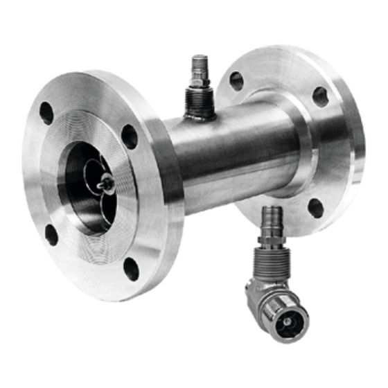
Section 1—Introduction Barton 7000 Series Flowmeters Barton 7000 Series flowmeters are specially designed to accommodate a broad range of precise fluid measurement applications. They can accept larger flow rates with lower pressure drops than other meters in their class, and fea- ture a self-flushing design for longer sustained accuracy. -
Page 4: Pressure Boundary Certification
Section 1 Model 7000 Series Turbine Flowmeter • ATEX certified, EEx d IIC (Model 7100, 7200, 7300) • Measurement Canada Custody Transfer Certification G-0210 (Model 7400) • Canadian Registration Number 0F0123.2C (Model 7400) • Intrinsically Safe/Non-incendive approved to various standards as governed by the certification of the readout device and the specific entity parameters of the pickup coils listed with that device. -
Page 5: Specifications-Standard Pickup Coil
Model 7000 Series Turbine Flowmeter Section 1 Shielded wire cable conveys the output of the pickup coil to compatible elec- tronic instruments to indicate flow rate, record, and/or totalize the volumet- ric flow. Since the coil itself does not require electrical power, the standard pickup coil incorporates connection pins that mate to a quick connector. - Page 6 Section 1 Model 7000 Series Turbine Flowmeter...
-
Page 7: Section 2-Installation And Operation
Model 7000 Series Turbine Flowmeter Section 2 Section 2—Installation and Operation Unpacking All Barton flowmeters are tested and inspected during manufacture. However, the instrument should be inspected at time of unpacking to detect any damage that may have occurred during shipment. Unpacking Procedure For applications requiring special cleaning/precautions, a polyethylene bag is used to protect the instrument from contamination. - Page 8 Section 2 Model 7000 Series Turbine Flowmeter WARNING: The customer is responsible for ensuring chemical compatibility between the flowmeter and any fluids being metered. Never exceed the maximum recommended pressure and temperature limits. Never exceed the maximum recommended flow rate for the meter. For installations where the pressure could exceed the rated maximum safe working pressure of the turbine meter housing or flanges, the piping system must include protective measures to prevent over pressure, in accordance with applicable local and national piping code. The turbine meter is not designed for high static or dynamic loads at the end connections. The piping system must be designed with adequate supports to minimize the loads at the turbine meter, in accordance with applicable local and national piping code. The turbine meter may be under pressure. Ensure that the piping system is completely depressurized before removing the meter for maintenance or inspection.
-
Page 9: Best Practices For Installation
Model 7000 Series Turbine Flowmeter Section 2 Best Practices for Installation Before installing a Barton turbine flowmeter, read the following best practices in their entirety. Filtration All meters should be installed with upstream filtration to isolate the meter from damage from foreign objects in the piping system. See the Barton 7000 Series product data sheet for recommended filtration size. -
Page 10: Flowmeter Location
Section 2 Model 7000 Series Turbine Flowmeter Flowmeter Location See Figure 2.1 for reference. Location of the flowmeter to obtain optimum accuracy is dependent upon several factors. • Relative to the System—When the flow is expected to be intermittent, the meter should not be mounted at a low point in the piping system since solids can settle on, or congeal around the rotor. - Page 11 Model 7000 Series Turbine Flowmeter Section 2 Figure 2.1—Flowmeter piping arrangements...
-
Page 12: Bolt Size/Torque Requirements
Section 2 Model 7000 Series Turbine Flowmeter Bolt Size/Torque Requirements Bolt sizes vary with meter size and flange rating. See Table 2.4 for bolt speci- fications recommended in ASME B16.5-2003. Torque requirement vary with meter size, threads, and fitting/nut material. See Table 2.2 for recommended torque values. -
Page 13: System Pressure
Model 7000 Series Turbine Flowmeter Section 2 System Pressure The maximum and minimum system pressures must be considered when installing the turbine meter into the system. • Minimum Meter Pressure—To obtain proper response, a back pressure should be applied to the meter. This back pressure should be at least twice the pressure drop of the meter at maximum flow (all meters). - Page 14 Section 2 Model 7000 Series Turbine Flowmeter The section of straight pipe upstream must be 20 in.; the section down- stream must be 10 in.) Do not install throttling valves within 100 pipe diameters upstream of the flowmeter. Install a flow straightener upstream and downstream of the meter. The applicable filter should be selected according to ISA Standard RP31.1.
- Page 15 Model 7000 Series Turbine Flowmeter Section 2 Table 2.3 Pressure Ratings (PSI) — Type 316 SST 7000 Series Turbine Meters with ASME B16.5 Flanges Flange -20°F 100°F 200°F 300°F 400°F 500°F 600°F 650°F 700°F 750°F Class (-29°C) (38°C) (93°C) (149°C) (204°C) (260°C) (316°C) (343°C) (371°C) (399°C) CL 150 CL 300 CL 400 CL 600 1440 1440 1240...
- Page 16 Section 2 Model 7000 Series Turbine Flowmeter Table 2.5 Pressure Ratings (Bar) — Flange Type 316 SST 7000 Series Turbine Meters with ASME B16.5 Flanges Class -29°C 38°C 50°C 100°C 150°C 200°C 250°C 300°C 325°C 350°C CL 150 19.0 19.0 18.4 16.2 14.8 13.7 12.1 10.2 CL 300 49.6 49.6 48.1 42.8 38.5 35.7 33.4 31.6...
-
Page 17: Section 3-Maintenance
Model 7000 Series Turbine Flowmeter Section 3 Section 3—Maintenance Barton 7000 Series flowmeters have a proven history of providing long cycle periods between maintenance intervals. It is recommended the meters be inspected every 3 to 5 years unless measurement anomalies occur. Many installations are suitable for much longer maintenance cycles. -
Page 18: Parts Replacement
Section 3 Model 7000 Series Turbine Flowmeter Parts Replacement See Table 3.1 for a list of recommended spare parts. WARNING: Use only spare parts identified in this manual. Cameron bears no legal responsibility for the performance of a product that has been serviced or repaired with parts that are not authorized by Cameron. Table 3.1—Electrical Spare Parts Pickup Coils Meter Size Temperature Rating Part Number 1/4-in. through 3/4-in. -450°F to +450°F 9A-2112-0001A-01 (-268°C to +232°C) -58°F to +347°F 9A-2113-0001A-01* (-50°C to +175°C) - Page 19 Model 7000 Series Turbine Flowmeter Section 3 Table 3.2—Model 7100 Kits Model Meter Size Part Number 7184 1/2" 9A-7084-9001-BA-01 7185 5/8" 9A-7085-9001-BA-01 7186 3/4" 9A-7086-9001-BA-01 7101 1" 9A-7001-9001-BA-01 7145 1-1/4" 9A-7045-9001-BA-01 7146 1-1/2" 9A-7046-9001-BA-01 7102 2" 9A-7002-9001-BA-01 7103 3" 9A-7003-9001-BA-01 7104 4" 9A-7004-9001-BA-01 7106 6"...
- Page 20 Section 3 Model 7000 Series Turbine Flowmeter Table 3.5—Model 7400 Kits Model Meter Size Part Number 7486 3/4" 9A-7086-9001-BA-04 7450 1" 9A-7050-9001-BA-04 7475 1" 9A-7075-9001-BA-04 7401 1" 9A-7001-9001-BA-04 7445 1-1/4" 9A-7045-9001-BA-04 7446 1-1/2" 9A-7046-9001-BA-04 7402 2" 9A-7002-9001-BA-04 7403 3" 9A-7003-9001-BA-04 7404 4" 9A-7004-9001-BA-04 7406 6"...
-
Page 21: Disassembly/Assembly
Section 3 Disassembly/Assembly WARNING: Before disassembling or assembling a Barton turbine flowme- ter, read all safety cautions and warnings on pages 7 and 8. A special tool can be fabricated for disassembling Barton 7000 Series flow- meters. See Figure 3.1 for a fabrication diagram. Figure 3.1—Flowmeter disassembly tool Model 7100 Fractional-Sized Flowmeters IMPORTANT: Field repairs for 1/4 in. and 3/8 in. Model 7100 flowmeters are not recom- mended. -
Page 22: Model 7100/7300 Flowmeters (1 In. And Larger)
Section 3 Model 7000 Series Turbine Flowmeter Model 7100/7300 Flowmeters (1 in. and larger) Remove downstream locknut (see Figure 3.3, page 23). Insert hook end of special disassembly tool into downstream flow straightener tube and engage hook on inside edge of tube. Slide impact hammer along tube, striking the anvil. - Page 23 Model 7000 Series Turbine Flowmeter Section 3...
-
Page 24: Model 7200/7400 Flowmeters
Section 3 Model 7000 Series Turbine Flowmeter Model 7200/7400 Flowmeters Remove the downstream locknut (see Figure 3.4). Insert the hook end of the special disassembly tool into the downstream flow straightener tube and engage the hook on the inside edge of tube. Slide the impact hammer along tube, striking the anvil. -
Page 25: Electrical Pickup Coil Check
Model 7000 Series Turbine Flowmeter Section 3 Electrical Pickup Coil Check Items Needed: Ohmmeter and Oscilloscope With an ohmmeter, measure the resistance between the pickup pins. The resistance should be approximately 1200 ohms. Measure the resistance between each pin and the pickup coil housing. The resistance should be at least 100 megohms. - Page 26 Section 3 Model 7000 Series Turbine Flowmeter Fluid Delivery Greater Than Indicated on Totalizer Note: Verify that the proper "K" factor value is entered in the electronic readout device. Possible Cause Corrective Action Foreign material collected on rotor or Remove the meter from the line and visu- bearings.
- Page 27 Model 7000 Series Turbine Flowmeter Section 3 Possible Cause Corrective Action Excessive electrical noise. Unsheilded Ensure that the cable used to connect the cable used in close proximity to an elec- pickup to the totalizer is properly shielded trical motor can cause electrical noise, and grounded.
- Page 28 Section 3 Model 7000 Series Turbine Flowmeter...
-
Page 29: Section 4-Dimensional Drawings
Model 7000 Series Turbine Flowmeter Section 4 Section 4—Dimensional Drawings Figure 4.1 shows a typical installation of a Barton 7000 Series flowmeter. Refer to Tables 4.1 through 4.6, pages 30 to 35, for actual dimensions. Values are presented in inches unless otherwise stated. - Page 30 Section 4 Model 7000 Series Turbine Flowmeter Table 4.1—150# ANSI Dimensions Line No. of Dia. of Holes Dia. of B.C. Size Holes in. (mm) in. (mm) in. (mm) in. (mm) in. (mm) (in.) 3-1/2 2-1/2 2-3/8 (127) (88.9) (63.5) (15.9) (60.3) 3-1/2 2-1/2 2-3/8 (127) (88.9) (63.5) (15.9) (60.3) 3-1/2 2-1/2 2-3/8 (127) (88.9) (63.5) (15.9)
- Page 31 Model 7000 Series Turbine Flowmeter Section 4 Table 4.2—300# ANSI Dimensions Line No. Dia. of Holes Dia. of B.C. Size Holes in. (mm) in. (mm) in. (mm) in. (mm) in. (mm) (in.) 3-3/4 2-1/2 2-5/8 (127) (95.3) (63.5) (15.9) (66.7) 3-3/4 2-1/2 2-5/8 (127) (95.3) (63.5) (15.9) (66.7) 3-3/4 2-1/2 2-5/8 (127) (95.3) (63.5) (15.9)
- Page 32 Section 4 Model 7000 Series Turbine Flowmeter Table 4.3—600# ANSI Dimensions Line No. Dia. of Holes Dia. of B.C. Size Holes in. (mm) in. (mm) in. (mm) in. (mm) in. (mm) (in.) 3-3/4 2-1/2 2-5/8 (127) (95.3) (63.5) (15.9) (66.7) 3-3/4 2-1/2 2-5/8 (127) (95.3) (63.5) (15.9) (66.7) 3-3/4 2-1/2 2-5/8 (127) (95.3) (63.5) (15.9)
- Page 33 Model 7000 Series Turbine Flowmeter Section 4 Table 4.4—900# ANSI Dimensions Line No. Dia. of Holes Dia. of B.C. Size Holes in. (mm) in. (mm) in. (mm) in. (mm) in. (mm) (in.) 4-3/4 3-1/2 3-1/4 (177.8) (120.7) (88.9) (22.2) (82.6) 4-3/4 3-1/2 3-1/4 (177.8) (120.7) (88.9) (22.2) (82.6) 4-3/4 3-1/2 3-1/4 (177.8) (120.7) (88.9) (22.2)
- Page 34 Section 4 Model 7000 Series Turbine Flowmeter Table 4.5—1500# ANSI Dimensions Line No. Dia. of Holes Dia. of B.C. Size Holes in. (mm) in. (mm) in. (mm) in. (mm) in. (mm) (in.) 4-3/4 3-1/2 3-1/4 (177.8) (120.7) (88.9) (22.2) (82.6) 4-3/4 3-1/2 3-1/4 (177.8) (120.7) (88.9) (22.2) (82.6) 4-3/4 3-1/2 3-1/4 (177.8) (120.7) (88.9) (22.2)
- Page 35 Model 7000 Series Turbine Flowmeter Section 4 Table 4.6—2500# ANSI Dimensions Line No. Dia. of Holes Dia. of B.C. Size Holes in. (mm) in. (mm) in. (mm) in. (mm) in. (mm) (in.) 6-1/4 4-1/4 (203.2) (158.8) (101.6) (25.4) (108.0) 1-1/4 7-1/4 1-1/8 5-1/8 (203.2) (184.1) (101.6) (28.6) (130.2) 1-1/2 4-1/2 1-1/4 5-3/4 (228.6) (203.2) (114.3)
- Page 36 The warranty does not extend to or apply to any unit which has been repaired or altered at any place other than at Cameron’s factory or service locations by persons not expressly approved by Cameron. Product Brand Barton® is a registered trademark of Sensia.
Need help?
Do you have a question about the Barton 7000 Series and is the answer not in the manual?
Questions and answers