
Related Manuals for Sensia LEFM 2010FE


Summary of Contents for Sensia LEFM 2010FE
- Page 1 ® CALDON ULTRASONICS ® LEFM 2010FE Ultrasonic Flowmeter User Manual February 2014 IB1009 Rev. 7...
- Page 2 IB1009 Rev. 7 LEFM 2010FE Transmitter User Manual RECEIPT OF EQUIPMENT Prior to uncrating, check outside packing case for visible damage. Notify local carrier at once if damage is present. Inspect unit for damaged or missing parts. Contact Cameron at (724) 273-9300 to report damage.
-
Page 3: Table Of Contents
1.0 EQUIPMENT SPECIFICATION ..................3 LEFM 2010FE Equipment....................3 1.1.1 LEFM 2010FE Transmitter ....................3 1.1.2 LEFM 2010FE Metering Section...................4 LEFM 2010FE Transmitter Part Code................4 1.2.1 LEFM 2010FE Transmitter ....................5 1.2.2 Environment .........................6 2.0 INSTALLATION........................7 Transmitter and Terminations ..................7 2.1.1... - Page 4 IB1009 Rev. 7 LEFM 2010FE Transmitter User Manual Analog Input/Output Verification Procedure ..............37 5.7.1 Current Inputs........................38 5.7.2 RTD Inputs.........................40 5.7.3 Analog Outputs........................40 Analog Input Verification....................41 Analog Output and Pulse Output Verification .............. 41 5.9.1 Force Output (Analog) ......................41 5.9.2...
-
Page 5: Introduction
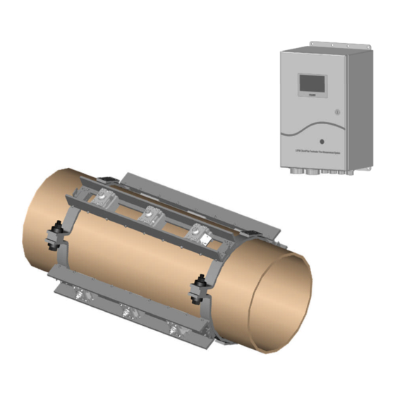
IB1009 Rev. 7 INTRODUCTION The Caldon LEFM 2010FE Ultrasonic Flow Transmitter is a highly sophisticated flow measurement system. It employs the ultrasonic transit time method to measure fluid velocity and flow rate. It contains advanced signal and data processing circuitry to achieve high accuracy and repeatability. It also contains an automatic self-checking system to continuously verify that it is performing properly and to initiate warnings and alarms when unsatisfactory conditions are detected. -
Page 6: Terms Used In This Manual
Cameron is not responsible for damages or injuries sustained as a result of inappropriate use. Before performing system verification and repair procedures, contact Sensia Measurement Systems. For additional information or assistance on the application, operation or servicing, write or call the Sensia office nearest you or visit www.sensiaglobal.com... -
Page 7: Equipment Specification
Transducer fixture that holds the transducers to the pipe surface 1.1.1 LEFM 2010FE Transmitter The LEFM 2010FE Transmitter is a wall mount unit with the following special features: Standard Outputs: Flow Pulse (0-5 V standard, 0-12 V optional); the meter K factor is programmable (minimum... -
Page 8: Lefm 2010Fe Metering Section
1.2 LEFM 2010FE Transmitter Part Code As a member of the Cameron product family, each LEFM 2010FE Transmitter has a part code that completely defines the construction and features of the flow meter. Table 1-1 defines the part code. -
Page 9: Lefm 2010Fe Transmitter
LEFM 2010FE Transmitter User Manual IB1009 Rev. 7 LEFM 2010FE Specifications 1.2.1 LEFM 2010FE Transmitter Material: NEMA 4X Stainless Steel NEMA 4 Painted Carbon Steel Wall Mount Net Weight: 30 lbs. (13.6 kg) (See Figure 2-1 for dimensions) Power Requirements... -
Page 10: Environment
IB1009 Rev. 7 LEFM 2010FE Transmitter User Manual 1.2.2 Environment Indoor or Outdoor Use Altitudes up to 3000 meters Pollution – Degree 2 Power Supply ±10% of nominal voltages Storage Temperature Transducer Cable: Transmitter: -70°F (-57°C) to 158 F (70°C) °... -
Page 11: Installation
2.1 Transmitter and Terminations The LEFM 2010FE meter is designed to be used under a wide variety of environmental conditions. Durable construction permits conventional installation practices. The transmitter should be installed in an environment consistent with the ratings of the enclosure. All wiring to and from the transmitter must be put in grounded metal conduit or equivalent. -
Page 12: Rs-485 Communication
2.1.4 Digital Outputs The LEFM 2010FE Transmitter is a bidirectional meter and has two digital output options that indicate direction. The first is quadrature pulse output to indicate direction of flow (reference Table 2-4). Quadrature output uses two pulse outputs (A and B). Pulse output A leading pulse output B by 90° indicates forward flow while pulse output B leading pulse output A by 90°... - Page 13 LEFM 2010FE Transmitter User Manual IB1009 Rev. 7 Figure 2-1: Transmitter Enclosure (units in inches, [mm]) February 2014 Page 9 Installation...
- Page 14 IB1009 Rev. 7 LEFM 2010FE Transmitter User Manual On/Off Breaker RS-485 Power Digital I/O Analog I/O Transducers See Figure 2-2A Figure 2-2: Electronics with Door Open Circuit Breaker – ON to the LEFT, OFF to the RIGHT Installation Page 10...
- Page 15 LEFM 2010FE Transmitter User Manual IB1009 Rev. 7 Jumper “2” wire – RS485 “4” wire – RS485 E1 (pins 1&2) E1 (pins 3&2) E2 (pins 1&2) E2 (pins 3&2) Indicates Unit Operating Power Supply Check ± 12Vdc ± 5 Vdc Top View Figure 2-2a –...
- Page 16 BPL-TB2 BPL-TB2 Cross Path 3 DN Shield BPL-TB2 BPL-TB2 BPL-TB2 Diagonal Path 4 DN Shield BPL-TB2 BPL-TB2 BPL-TB2 Cross Path 4 DN Shield BPL-TB2 BPL-TB2 Table 2-1: LEFM 2010FE Transducer Terminations (For 8 acoustic paths) Installation Page 12 February 2014...
- Page 17 BPL-TB1 BPL-TB1 Shield BPL-TB1 Diagonal Path 3 DN Diagonal Path 2 DN BPL-TB1 BPL-TB1 Shield BPL-TB1 Diagonal Path 4 DN Cross Path 2 DN BPL-TB1 Table 2-2: LEFM 2010FE Transducer Terminations (For 4 acoustic paths) February 2014 Page 13 Installation...
- Page 18 IB1009 Rev. 7 LEFM 2010FE Transmitter User Manual RTD Connections 0, 4-20mA Connection Analog Input Source Description Terminus Description Terminus 0, 4-20mA + BPL-TB4-1 Analog Input 1 0, 4-20mA - BPL-TB4-2 Chassis Ground BPL-TB4-3 0, 4-20mA + BPL-TB4-7 Analog Input 2...
- Page 19 LEFM 2010FE Transmitter User Manual IB1009 Rev. 7 Name Signal Description Terminus Pulse A +V, Indicates forward flow BPL-TB6-1 GND5 Signal Ground BPL-TB6-2 +V, Pulse 90 degrees phase shift to Pulse A Pulse B or If phase lags (positive flow) - if phase leads (negative flow)
- Page 20 IB1009 Rev. 7 LEFM 2010FE Transmitter User Manual Port RS-485 Full Duplex* RS-485 Half Duplex* Termination Name E1, E2 Jumpered 2-3 E1, E2 Jumpered 1-2 BPL-TB5-1 A, Noninverting Receive (+Rx) BPL-TB5-2 B, Inverting Receive (-Rx) BPL-TB5-3 Signal Ground COM1 BPL-TB5-4...
-
Page 21: Meter Installation Check-Out
LEFM 2010FE Transmitter User Manual IB1009 Rev. 7 2.2 Meter Installation Check-Out The following steps are recommended to checkout a meter’s installation. See Section 5 and 6 for troubleshooting and maintenance. Also reference Cameron procedure EFP-54. Step 1: Verify all field terminations have proper continuity and isolation from each other and earth. Verify connections are good with respect to insulation. -
Page 22: Operation
3.0 OPERATION 3.1 Measuring Flow The LEFM 2010FE uses pairs of ultrasonic transducers (Reference Figure 3-1) mounted externally on the pipe, typically in a bounce path configuration, to send acoustic pulses to one another along a measurement path. The measurement path is at an angle to the fluid flow. The acoustic pulses transit time depends upon both the speed of sound in the fluid and the velocity of the fluid along the path. - Page 23 LEFM 2010FE Transmitter User Manual IB1009 Rev. 7 The path angles in the pipe wall and fluid are determined by Snell’s Law. Where Fluid sound velocity Pipe shear sound velocity Wedge sound velocity Fluid Path angle ...
-
Page 24: Lefm 2010Fe Transmitter
Fifth Edition, 1983. 3.4 Remote Data Communications The LEFM 2010FE has two RS 485 communication ports using the Modbus protocol. See the Modbus Manual for more detail. Another serial port located on the electronics door is dedicated to the IR serial interface. -
Page 25: Display Operation
WARNING 4.3 Infrared Interface An infrared port is also mounted inside the display window for accessing the LEFM 2010FE via a Pocket PC running PocketLink software or other device operating with a Modbus protocol. LEFM Link software allows the user to interface with the transmitter via Modbus using a Pocket PC or a PC. For details, see the LEFM Link manual. -
Page 26: Display
IB1009 Rev. 7 LEFM 2010FE Transmitter User Manual 4.4 Display The transmitter has a graphics display. The display shows the meter’s indicated flow, totalized flow, fluid properties, and diagnostics data. The transmitter repeatedly cycles through all display parameters. The display provides information for each of the meter’s paths. The display cycle when in Normal Mode is... -
Page 27: Boot Up And Normal Operational Screens
LEFM 2010FE Transmitter User Manual IB1009 Rev. 7 4.4.1 Boot up and Normal Operational Screens On power up and boot up, a “splash screen” will appear displaying the part number and the checksum for the executable program (see below). Boot up and Normal Operation Display Screen Approximately 5 seconds after powering on the transmitter, the following Main Display screen appears displaying the total accumulated volume and the current flow rate. - Page 28 IB1009 Rev. 7 LEFM 2010FE Transmitter User Manual The second screen in the display cycle contains acoustic path diagnostic data. Information for Paths 5-8 (for an 8 path meter only) will be displayed on the next cycle through the screens.
- Page 29 LEFM 2010FE Transmitter User Manual IB1009 Rev. 7 Following Display 3, the Main Display screen will be displayed and repeat three times. Next will follow the first Fluid Properties screen which displays Density and Velocity of Sound (VOS). Density Units are...
-
Page 30: Path Level Alarm Display Screens
IB1009 Rev. 7 LEFM 2010FE Transmitter User Manual 4.4.2 Path Level Alarm Display Screens When in a Path Level Alarm condition, Display 6 will replace Display 1 (the displays will continue to cycle as in Figure 4-1). The display will contain alarm data on the bottom for each path and will alternate between displaying a flow or a totalizer value at the top. - Page 31 LEFM 2010FE Transmitter User Manual IB1009 Rev. 7 Figure 4-2: Display Screens in Meter State Alarm Mode Display 6 (Alarm) Main Display Flow or Total and Alarm Display 3 Meter State Time, Status, A/I (Repeat 3 times) Display 2 Display 4...
-
Page 32: Output Test Mode
4.5 Output Test Mode For test and/or validation purposes, an operator can temporarily override the output of the LEFM 2010FE and set the output to a fixed value using the Output Test mode. The user places the instrument in the Output Test mode using the LEFM Link software. -
Page 33: Switch Forced Setup
LEFM 2010FE Transmitter User Manual IB1009 Rev. 7 4.7 Switch Forced Setup If CTC dip switch SW1-8 (see Table 5-2) is set in the UP position during boot-up, the transmitter will wait for a new setup file to be sent before running. While waiting for a new setup file, the transmitter’s communication parameters will default to a baud rate of 9600 and a Modbus address of “1”. -
Page 34: Maintenance
LEFM 2010FE Transmitter. These procedures may be incorporated into a plant’s standard maintenance program. This section includes procedures for maintaining the LEFM 2010FE Transmitter that are designed for a trained maintenance technician to perform. These procedures may require the maintenance person to reference schematics, system connection diagrams, and construction outlines in Section 1.0. -
Page 35: Internal Electronics Inspection
5.2.2 Internal Electronics Inspection a. If necessary, remove power to the LEFM 2010FE by opening circuit breaker CB1. b. Put on an ESD (Electrostatic Discharge) protective wrist strap. Connect ESD protective wrist strap to a known ground; any part of enclosure structure is an acceptable ground. -
Page 36: Power Supply Voltage Troubleshooting And Maintenance
IB1009 Rev. 7 LEFM 2010FE Transmitter User Manual 5.3 Power Supply Voltage Troubleshooting and Maintenance I/O LED – Red -- Off When Normal CTC LED – Red -- Off When Normal MXR LED – Red -- Off When Normal RS-485 Selection: Power Supply LED –... -
Page 37: Ctc Troubleshooting And Maintenance
LEFM 2010FE Transmitter User Manual IB1009 Rev. 7 The following table provides the specified backplane voltage. Terminal Name Requirement TB9-1 5 Volts 5 ±0.1 Volts TB9-2 +12 Volts +12 ±0.5 Volts TB9-3 -12 Volts -12 ±0.5 Volts TB9-4 Ground Electrical Ground, 0V Table 5-1: Required Backplane Test Voltages 5.4 CTC Troubleshooting and Maintenance... - Page 38 IB1009 Rev. 7 LEFM 2010FE Transmitter User Manual The CTC has a battery (B1) in Figure 5-2. The battery (Panasonic CR1632) is used to backup the time and date on the device as well as variables used when acoustic paths fail. Cameron does NOT recommend changing the battery without consultation.
-
Page 39: Mxr Troubleshooting And Maintenance
LEFM 2010FE Transmitter User Manual IB1009 Rev. 7 5.5 MXR Troubleshooting and Maintenance Fuse, F3 0.125 Amp +150V Fuse, F2 Top View 0.5 Amp -12V TP = +150V Fuse, F1 TP = -150V 0.5 Amp +12V Figure 5-3: MXR Fuse Location... -
Page 40: Iob Troubleshooting And Maintenance
IB1009 Rev. 7 LEFM 2010FE Transmitter User Manual 5.6 IOB Troubleshooting and Maintenance Figure 5-4A: IOB Fuse Location – Top View Figure 5-4B: IOB Fuse Location – Rear View Maintenance Page 36 February 2014... -
Page 41: Analog Input/Output Verification Procedure
Table 5-3: IOB Fuse Location and Rating 5.7 Analog Input/Output Verification Procedure This procedure tests the analog inputs and outputs of the LEFM 2010FE Transmitter. The Transmitter, through the use of an input/output board (IOB), converts an isolated analog input signal (current) into a voltage readable by the CTC board. -
Page 42: Current Inputs
IB1009 Rev. 7 LEFM 2010FE Transmitter User Manual 5.7.1 Current Inputs Step 1: Connect the test equipment as follows: Current Inputs 0-20 mA Source (DC Calibrator) Output 1 2 3 4 5 6 Analog In Terminal Block BPL-TB4 RTD Inputs... - Page 43 LEFM 2010FE Transmitter User Manual IB1009 Rev. 7 Refer to Table 5-3 for the specific connection terminals on EUA. Analog Input Positive Negative Channel Excitation Terminal Terminal Excitation BPL-TB4-1 BPL-TB4-2 BPL-TB4-7 BPL-TB4-8 BPL-TB3-2 BPL-TB3-4 BPL-TB3-1 BPL-TB3-3 Analog Output Positive Negative...
-
Page 44: Rtd Inputs
IB1009 Rev. 7 LEFM 2010FE Transmitter User Manual 5.7.2 RTD Inputs Step 1: Connect the RTD calibrator as shown in Figure 5-5. Using LEFM Link, scale the analog inputs according to the specific RTD used. Using the RTD Calibrator, input five temperatures (equally separated and covering the range of the module). -
Page 45: Analog Input Verification
LEFM 2010FE Transmitter User Manual IB1009 Rev. 7 5.8 Analog Input Verification The LEFM may have an analog input (for example, temperature, pressure, or density). The input signal is conditioned before it is converted to a digital input. The input is scaled linearly to convert the user input of 4-20 mA (or 0-20 mA) to maximum and minimum values. -
Page 46: Metering Section And Transducer Cables
IB1009 Rev. 7 LEFM 2010FE Transmitter User Manual Table 5-7—Digital Output Voltage Jumper Positions Jumper Voltage Position 5.10 Metering Section and Transducer Cables 5.10.1 Metering Section Inspection Some steps in this procedure may require handling components at temperatures approaching 500°F (260°C) - if performed when the power plant is operating. Use insulated gloves to perform this procedure. -
Page 47: Transducers
SURFACE The transducer should be evaluated using the following steps: Step 1: Power down the LEFM 2010FE transmitter (set circuit breaker to the right hand position) and remove the transducer assembly (see EFP20). Step 2: Verify the transducer pad or wedge is clean and free from dirt. Remove any dirt or foreign material that may be present. -
Page 49: Troubleshooting And Diagnostics For The Ultrasonics
6.0 TROUBLESHOOTING AND DIAGNOSTICS FOR THE ULTRASONICS 6.1 Diagnostics The LEFM 2010FE Transmitter interfaces via a serial port or infrared port to external devices. The Transmitter uses the Modbus protocol. Cameron provides PC (laptop) software, LEFM Link, to interface with the Transmitter via Modbus. Alternatively, the Cameron Modbus manual can be used to select the appropriate registers. -
Page 50: Meter Troubleshooting
IB1009 Rev. 7 LEFM 2010FE Transmitter User Manual 6.3 Meter Troubleshooting The following codes are used to indicate the Meter State alarms as shown on the Meter State Screen (reference Display 3 – Section 4.4.3): Alarm Description Display Code Modbus Code... -
Page 51: Path Failure
If this alarm is displayed, the CTC board should be replaced. 6.4 Path Troubleshooting The LEFM 2010FE System continuously checks the data quality of each acoustic path. Each time the signal is sampled, the MXR/CTC tests the signal as follows: ... -
Page 52: Path Reject Status
When the path status indicates that the Reject Test failed, it indicates that the percentage of data that has been rejected has exceeded the LEFM 2010FE System thresholds. The following troubleshooting sequence can be followed to pinpoint the root cause. - Page 53 LEFM 2010FE Transmitter User Manual IB1009 Rev. 7 Step 5: Determine Which Transducer Has Failed Using the acoustic paths, follow these steps to determine which transducer to evaluate: Review the SNR (Signal to Noise Ratio) for each path (paths 1 through 8). The SNR should be greater than 15.
- Page 54 IB1009 Rev. 7 LEFM 2010FE Transmitter User Manual Triggering ½ Cycle ZCD Ratio 2 46 Tim e (nsec) Time (s) Figure 6-1: Example Transducer Waveform Individual acoustic path waveforms can be viewed by using the Dip Switches (SW1) on the front side of the CTC (reference Figure 5-2).
-
Page 55: Calculation Error
6.4.2 Calculation Error This alarm alerts users to a computational failure within the LEFM 2010FE software. An illegal operation or attempting to divide a number by zero will trigger this alarm. Most often this alarm is displayed during the meter setup if a wrong value is entered. After the system is operational, this alarm should not occur. -
Page 56: Impedance Failure
IB1009 Rev. 7 LEFM 2010FE Transmitter User Manual 6.4.6 Impedance Failure This test measures the impedance of the positive (+) and negative (-) polarity to ground on each transducer pair (+UP, -UP, +DN, -DN). A measured impedance less than the threshold results in this Fail state. -
Page 57: Modbus Id And Baud Rate
LEFM 2010FE Transmitter User Manual IB1009 Rev. 7 6.5.1 Modbus ID and Baud Rate All Cameron transmitters are programmed with Modbus ID set to 1, Baud Rate at 9600 and in RTU Slave Mode. If the transmitter has been reprogrammed with a different setting and this setting is not known or lost, simply set Control Selector switch (DIP Switch) Number to 2 to up (TRUE) and toggle the reset switch. -
Page 58: Recommended Spare Parts
IB1009 Rev. 7 LEFM 2010FE Transmitter User Manual 7.0 RECOMMENDED SPARE PARTS Qty: 5 F1 - Littelfuse 154.125 – 125mA fast acting (FF) Qty: 1 F2 - Littelfuse 154.2 – 2000mA fast acting (FF) Qty: 2 F7/F10 - Littelfuse 154.5 – 500mA fast acting (FF) Qty: 1 CTC Board –... - Page 59 Seller will pass only through to its purchaser of such items the warranty granted to it by the manufacturer. Sensia LLC 200 Westlake Park Blvd...
Need help?
Do you have a question about the LEFM 2010FE and is the answer not in the manual?
Questions and answers