Table of Contents
Advertisement
Quick Links
Advertisement
Table of Contents
Troubleshooting

Related Manuals for Sensia NUFLO Scanner 1140G


Summary of Contents for Sensia NUFLO Scanner 1140G
- Page 1 NUFLO Scanner 1140 RTU Hardware User Manual...
- Page 2 © 2010 Cameron International Corporation (“Cameron”). All information contained in this publication is confidential and proprietary property of Cameron. Any reproduction or use of these instructions, drawings, or photographs without the express written permission of an officer of Cameron is forbidden. All Rights Reserved.
- Page 3 Warranty The Company warrants all products of its manufacture and bearing its nameplate for a period of one year after date of shipment from its factory to be free from defects in material and workmanship subject to the following: The Company’s liability under this warranty is limited, in the sole and absolute discretion of the Company, to refunding the purchase price, to repairing, or to replacing parts shown to the satisfaction of the Company to have been defective when shipped and then only if such defective parts are promptly delivered to its factory, transportation charges prepaid.
- Page 4 Product Warranty Statement The warranty applicable to this product is stated at the beginning of this manual. Should any problem arise after-delivery, please contact Cameron’s Measurement Systems Division HelpDesk at 1-877-805-7226 or the Customer Service department during normal business hours at (403) 291-4814.
-
Page 5: Table Of Contents
TABLE OF CONTENTS INTRODUCTION......................9 Overview of the Scanner 1140 ..........................9 Scanners 1140T, 1140C, 1140L, and 1140G....................10 Scanner Software .............................. 10 CHAPTER 1: INSTALLATION ..................11 Quick Start................................11 Operating/Storage Limitations ..........................12 Unpacking ................................12 Mounting ................................12 ... - Page 6 Scanner 1140 Hardware User Manual Switch Control DIP Switch (SW4) Summary ....................35 Superboot Switch.............................. 37 Lithium Battery Switch............................. 37 Analog Transmitter Inputs (Resources A09 – A10)..................... 38 Analog 4-20 mA Transmitter..........................38 Analog 1-5 Vdc Transmitter (TxPwr) ......................38 Analog 4-20 mA Output (Optional) ........................
- Page 7 Table of Contents NVRAM Lithium Battery Voltage........................69 NVRAM Battery Change Procedure ........................ 69 Returning the Scanner ............................70 CHAPTER 5: DPE+ INSTALLATION................. 71 DPE+ Installation ..............................71 Replacing a DPE with a DPE+ Transducer ...................... 71 Gasket Options.............................. 72 ...
- Page 8 Scanner 1140 Hardware User Manual DPE+ Multi-Variable Transducer........................90 Transmitter Power Supply ..........................91 Power Supply Options ............................91 6 Volt Rechargeable Battery ......................... 92 Alkaline Battery ............................92 DC Input................................ 92 12 Volt Rechargeable Battery ........................93 Software ................................93 ...
-
Page 9: Introduction
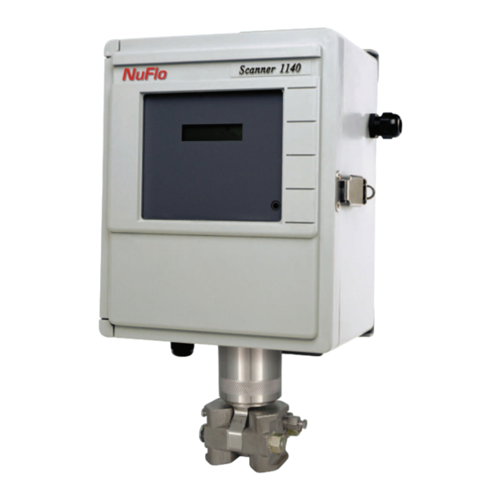
Introduction Overview of the Scanner 1140 ® The Scanner 1140 is an economical, single stream measurement Remote Terminal Unit (RTU) with flow and pressure control capability. It offers a powerful alternative to chart recorders in gathering data for natural gas production and includes a full range of operator selectable mass, energy and volume algorithms. -
Page 10: Scanners 1140T, 1140C, 1140L, And 1140G
Scanner 1140 Hardware User Manual Scanners 1140T, 1140C, 1140L, and 1140G The Scanner 1140T, often referred to as the standard Scanner 1140 unit, is a 6Vdc EFM rated for Class I, Div.1 Intrinsically Safe applications. The device has no integral communications. It is housed in a fiberglass- reinforced plastic enclosure. -
Page 11: Chapter 1: Installation
Chapter : Installation CAUTION POWER TO THE SCANNER 1140 MUST BE TURNED OFF PRIOR TO THE REMOVAL OF ANY ELECTRONIC CIRCUIT BOARDS OR DAMAGE TO THE SCANNER MAY RESULT. CIRCUIT BOARDS ARE SUBJECT TO DAMAGE IF EXPOSED TO STATIC ELECTRICITY. HANDLING AND INSTALLING CIRCUIT BOARDS MUST BE PERFORMED IN AN ENVIRONMENT FREE OF STATIC ELECTRICITY AND THE OPERATOR MUST BE GROUNDED. -
Page 12: Operating/Storage Limitations
Scanner 1140 Hardware User Manual Operating/Storage Limitations Temperature: The instrument is not to be subjected to ambient or operating temperatures beyond the range listed in the specification section (Page 85). Static Electricity: The circuit boards are not to be subjected to any source of external static electricity. Unpacking Cameron’s Measurement Systems Division Scanners are carefully inspected during manufacturing and before shipment. -
Page 13: Typical Installation Of Scanner 1140T
Chapter 1: Installation Typical Installation of Scanner 1140T Class I, Division 1, Groups C & D Intrinsically safe or Class I, Division 2, Groups A, B, C & D non-sparking... -
Page 14: Typical Installation - Scanner 1140C/L Integral Communications
Scanner 1140 Hardware User Manual Typical Installation - Scanner 1140C/L Integral Communications NuFlo... -
Page 15: Typical Installation (With Remote Communications)
Chapter 1: Installation Typical Installation (with Remote Communications) -
Page 16: Power Supply Connection
Scanner 1140 Hardware User Manual Power Supply Connection Conduit entry is provided on the right-hand side of the enclosure for the power supply/solar panel wires (refer to Page 97 Outline Dimensions for size and location of conduit entry. WARNING ALL METALLIC CONDUIT CONNECTORS MUST BE GROUNDED TO THE INTERNAL GROUND WITH THE SHORTEST WIRE POSSIBLE. -
Page 17: Scanner 1140T (With Battery Cover Removed)
Chapter 1: Installation Scanner Enclosure Solar Panel Wiring Connection Protective Warning Battery Label Cover Slot Local Communication Port Scanner 1140T (With Battery Cover Removed) -
Page 18: 12-Volt Battery Power Supply, Division 2 Controller
Scanner 1140 Hardware User Manual 12-Volt Battery Power Supply, Division 2 Controller The following configurations of the 1140 are suitable for Class I, Division 2 when installed as per Appendix A: Installation Drawings 9A-1140-11012). Scanner 1140C (Front View with Door Open) -
Page 19: Scanner 1140L (Front View With Door Open)
Chapter 1: Installation Scanner 1140L (Front View with Door Open) Scanner 1140G... -
Page 20: Solar Panel Installation And Connection
Scanner 1140 Hardware User Manual Solar Panel Installation and Connection Mount the solar panel on a post, or directly to an equator-facing (or, at the equator, upward-facing) flat surface – see chart below for tilt angles. The panel should be mounted high enough to prevent damage or tampering. -
Page 21: Flashing The Scanner
Chapter 1: Installation Flashing the Scanner “Flashing” is the term used to describe the procedure that installs a different version of firmware other than the one with which the Scanner was shipped. If changing the firmware is NOT necessary, the Startup Procedure (Page 28) may be initiated. -
Page 22: Configuration Lock Switch
Scanner 1140 Hardware User Manual Configuration Lock Switch The optional Configuration Lock Switch may be legally required in some locations. When installed, it is located to the left of Switch SW4 (see above diagram). It consists of a cover plate that normally covers the switch. -
Page 23: Flashing With Scanflash
Chapter 1: Installation 6. Set Switches SW4-5 to the “program” position (ON) and SW4-6 to the “FPGA boot” position (OFF). SW4 should now look like this: 7. Continue below or go to Page 26 if you are using ScanLoad. Flashing with ScanFlash The ScanFlash utility is loaded on your ScanWin installation CD. -
Page 24: Flashing With Winsload (In Windows)
Scanner 1140 Hardware User Manual Flashing with WinsLoad (in Windows) WinsLoad is used to flash the Scanner RTU using an MS Windows operating system. If you must operate in a DOS environment, go to the section on Flashing with ScanLoad (DOS) – Page Installing WinsLoad 1. - Page 25 Chapter 1: Installation 2. An MS-DOS window is automatically opened. WinsLoad checks the validity of the binary file and if it is all right, it displays a window similar to this one. 3. Now, “power up” the Scanner by moving the SW4-1 switch back to the “run”...
-
Page 26: Flashing With Scanload (Dos)
Scanner 1140 Hardware User Manual Flashing with ScanLoad (DOS) The use of ScanLoad should take place only if you are running in a DOS environment (not from within a DOS “shell” when running Windows). Use WinsLoad if you are operating in an MS Windows operating system. -
Page 27: Using Scanload
Chapter 1: Installation Using ScanLoad Before starting ScanLoad, perform the steps outlined in the section, Getting Ready to Flash (Page 21). The following steps is intended as an example of using the ScanLoad utility: 1. From the ScanLoad directory type: SCANLOAD NGM411F.B40, then press enter. (ScanLoad is the executable file to start the program and NGM411F.B40 is the binary file with the new firmware). -
Page 28: Startup Procedure
Scanner 1140 Hardware User Manual Startup Procedure Note: If the Scanner has been FLASHED or is NOT CONFIGURED, perform a Superboot. If it is already configured, it is not necessary to perform a superboot. Also, note that if a previous configuration was saved, it is possible to restore a configuration after a Superboot is performed. - Page 29 Chapter 1: Installation A series of messages appear on the local display as the Scanner 1140 performs its master reset sequence: Superboot found, Resetting unit **REMINDER** Setup unit for non-superboot. 4. Start ScanWin or ScanPC and set the time and date at the prompt. 5.
- Page 30 Scanner 1140 Hardware User Manual 8. Where legally required, the optionally installed Configuration Lock Switch may be enabled and the cover sealed. System Serial Port Frequency Pulse Switch (SW4) Switch (SW3) Input Switch (SW1) Display contrast Pulse Input Resource AO7 RS422 RS232 See main diagram RS485...
-
Page 31: Chapter 2: Main Board And Wiring
Chapter : Main Board and Wiring Main Circuit Board Diagram (Major Components) Display Contrast Frequency RS 485/ RS422 Industry Canada or RS232C Configuration Lock Switch System Switches Lithium Backup Battery Graphics Analog Output Program Memory 4-20 INPUT 128 K FLASH Memory Test 128 K... -
Page 32: Main Board Wiring Diagram
Scanner 1140 Hardware User Manual Main Board Wiring Diagram Note : Expansion Board decal is placed here. -
Page 33: Field Termination
Chapter 2: Main Board and Wiring Field Termination (6 Pin Input Connector – RS-232C setting) Source Terminal # Description A21 (Remote TxO – Gas chromatograph (secondary console) port transmit output Console) RxO – Gas chromatograph (secondary console) port receive input DSRO –... -
Page 34: Dip Switch Summary
Scanner 1140 Hardware User Manual Source Terminal # Description EXP 01 - Expansion board terminal #1 EXP 02 - Expansion board terminal #2 EXP 03 - Expansion board terminal #3 EXP 04 - Expansion board terminal #4 EXP 05 - Expansion board terminal #5 EXP 06 - Expansion board terminal #6 EXP 07 - Expansion board terminal #7 EXP 08 - Expansion board terminal #8... -
Page 35: Memory Switches
Chapter 2: Main Board and Wiring Memory Switches Switch Control DIP Switch (SW4) Summary The Switch SW4 located at the top left of the main board controls several important functions: ( SW4 ) System The following table summarizes SW4’s functions and settings: Switch # Description SW4-1... - Page 36 Scanner 1140 Hardware User Manual Below is a detailed description of the functions of each switch on the System Control Switch SW4: SW4-1: This switch performs a properly supervised system shutdown. Rather than simply driving the system RESET line, SW4-1 generates a power fail interrupt to the CPU, and after a 10 ms delay (for the power fail code to run) shuts the power off to the entire system board.
-
Page 37: Superboot Switch
Chapter 2: Main Board and Wiring SW4-8 This switch is to select either normal operation (ON) or a specialized factory test mode (OFF). SW4-8 should therefore be left in the ON (normal) position at all times. Superboot Switch A “Superboot” erases all configuration and flow data when power is turned ON. A superboot is required when first commissioning the unit (after turning the NVRAM battery switch ON). -
Page 38: Analog Transmitter Inputs (Resources A09 - A10)
Scanner 1140 Hardware User Manual Analog Transmitter Inputs (Resources A09 – A10) Analog 4-20 mA Transmitter (Intrinsically Safe only with barrier) Use of conventional 4-20 mA transmitters requires the addition of precision load resistors on each analog channel. Power for the current loop is normally drawn from an external source. 4-20 mA ANin1 ANin2... -
Page 39: Rtd Inputs (Resource A08)
Chapter 2: Main Board and Wiring RTD Inputs (Resource A08) (Intrinsically Safe when installed per Appendix A: Installation Drawings) Resource A08 is connected to 100Ω 3-wire platinum RTD as shown. The RTD characteristic curve is software- selectable for temperature coefficients of either 0.003902 or 0.00385 (Ω/Ω/°C) or by performing a loop calibration at three or more points (refer to the NGas/NFLo manuals (Section 2 - Analog and RTD Calibration) or to the ScanWin manual (Chapter 3 –... -
Page 40: Frequency Pulse Inputs (Resource A07)
Scanner 1140 Hardware User Manual Frequency Pulse Inputs (Resource A07) The 1140 frequency inputs are designed to interface with a variety of pulse producing sources, including turbine magnetic pickups, preamplified turbine signals, as well as contact closures and Pepperl & Fuchs inductive proximity sensors. -
Page 41: Three-Wire Preamplified Turbine (Barton 818) 0-5V Output
Chapter 2: Main Board and Wiring Three-Wire Preamplified Turbine (Barton 818) 0-5V Output (Non-Intrinsically Safe) - This is suitable for use with the Barton 818A preamplifier configured for voltage output mode. This preamplifier provides a transmission of up to 30 m. -
Page 42: Two-Wire Preamplified Turbine (Barton 818) 0.5 - 5.5 Ma Output
Scanner 1140 Hardware User Manual Two-Wire Preamplified Turbine (Barton 818) 0.5 - 5.5 mA Output (Non-Intrinsically Safe) - This is suitable for use with the Barton 818A preamplifier configured for current- loop output mode. This preamplifier provides a transmission of up to 5 Km. -
Page 43: Two-Wire Preamplified Turbine (Barton 818) 7-12 Ma Output
Chapter 2: Main Board and Wiring Two-Wire Preamplified Turbine (Barton 818) 7-12 mA Output (Non-Intrinsically Safe) - This is suitable for use with the Barton 818A preamplifier configured for current- loop output mode. This preamplifier provides a transmission of up to 5 Km. -
Page 44: Open Collector Without "Bounce
Scanner 1140 Hardware User Manual Open Collector without “Bounce” (Intrinsically Safe w/Barriers) This mode provides a generic pulse input, which is compatible with a variety of pulsers and other end devices. A suitable end device is one that provides a bounce-free solid state output stage, such as an open collector transistor or open-drain MOSFET. -
Page 45: Dry Contact
Chapter 2: Main Board and Wiring Dry Contact (Intrinsically Safe when installed as per Appendix A: Installation Drawings) In this mode, the pulse input is connected to any device that provides a passive contact closure, such as a reed relay or microswitch. Excitation is provided by the Scanner 1140. Debouncing circuitry limits the input frequency to 15 Hz maximum. -
Page 46: Status Inputs And Outputs (Resources A03, A04, A05 And A06)
Scanner 1140 Hardware User Manual Status Inputs and Outputs (Resources A03, A04, A05 and A06) (Intrinsically Safe w/Barriers) Status inputs are used to read the state of an external device, which can be either passive (e.g. contact closures) or active where excitation is from an external source. The type of input is selected by software. When a passive input is selected, an internal power source attempts to drive a 50-microampere current through the circuit. -
Page 47: Auxiliary Serial Port (Resource A02)
Chapter 2: Main Board and Wiring Auxiliary Serial Port (Resource A02) (Intrinsically Safe w/Barriers) The auxiliary serial port supports full RS-232C hardware handshaking signals and is used with a modem to ® ® provide remote communication or to connect peripheral devices such as the NuFlo MVX or MVX multivariable transmitters, Daniel gas chromatographs and ultrasonic meters to provide additional inputs via serial ports. -
Page 48: Auxiliary Serial Port Optional Dip Switch (Sw3)
Scanner 1140 Hardware User Manual Auxiliary Serial Port Optional DIP Switch (SW3) Note: If Switch (SW3) is not present, the default is RS-232. If SW3 Serial DIP Switch option has been installed, then RS-232/RS-422/RS-485 is switch selectable. The Auxiliary Serial Port Switch is located on the very top of the circuit board beside the System Control Switch (SW4): (SW3) Serial... -
Page 49: Mvx-Ii Wiring (Rs-485 Communications)
Chapter 2: Main Board and Wiring SW3-3: This switch forces the +5V to +12V charge pumping circuit to be permanently active and must be ON to generate the +8V VTX2 supply. When VTX2 is not in use SW3 should be left OFF to minimize power consumption. - Page 50 Scanner 1140 Hardware User Manual...
-
Page 51: Chapter 3: Optional Board And Wiring
Chapter : Optional Board and Wiring MIO1 Expansion Board The Scanner 1140 MIO1 expansion board is a multi-purpose I/O expansion card that provides an RS-232C/RS- 485/RS-422 serial port, a 1-5V/4-20 mA analog output and a multi-interface pulse input. Each of the interface types for these circuits is switch selectable. -
Page 52: Analog Output
Scanner 1140 Hardware User Manual Analog Output Quantity 1 (optional) Isolation Optically isolated to 500 V , externally powered Type Switch selectable as either 1-5V or 4-20 mA Accuracy ±0.1% of FS max. error @ 25°C (after software calibration) Temperature Effect ±1% of FS max. -
Page 53: I/O Termination
Chapter 3: Optional Board and Wiring I/O Termination Because Scanner 1140 expansion boards are limited to 10 points of I/O termination, not all of the I/O functionality available on the board can be accessed at the same time. The design therefore provides some interconnection flexibility between the terminal connections and the I/O circuitry so that a variety of configurations may be supported. - Page 54 Scanner 1140 Hardware User Manual The following diagram illustrates the position and orientation of this connector as well as the serial port, pulse input, and analog output configuration switches. Analog Out Select Serial Interface Select Pulse Input Mode Select RS422 5 6 7 8 RS232C RS485...
-
Page 55: Configuration Switches
Chapter 3: Optional Board and Wiring Configuration Switches As illustrated above, the board provides configuration switches for serial port, the pulse input and the analog output. A brief description of each of the switches is given below: Status Input/Output and Pulse Output Circuits All settings are software selected. -
Page 56: Pulse Input Mode Select Switch Settings
Scanner 1140 Hardware User Manual Pulse Input Mode Select Switch Settings Magnetic Pickup Coil Pin + Pin - Common Pin Numbers on MIO1 Boards Switch Setting Code Code Code Pin + Pin - Common Dry Contact Pin + Pin - Common Pin Numbers on MIO1 Boards System Setting... - Page 57 Chapter 3: Optional Board and Wiring Three-Wire Pre-Amplified Turbine (0-5V Output) 24V External Power Supply Pin + Pin - Common + out Pin Num bers on MIO1 Boards Switch S etting Code Code Code Pin + Pin - Com m on Two-Wire Pre-Amplified Turbine (.5-5.5 mA Output) 24V External Power Supply...
-
Page 58: Analog Output Switch
Scanner 1140 Hardware User Manual Two-Wire Pre-Amplified Turbine (7-12 mA Output) 24V External Power Supply Pin + Pin - Common + out Pin Num bers on MIO1 Boards Switch Setting Code Code Code Pin + Pin - Com m on Pepperl &... -
Page 59: Circuit Board Wiring Diagrams
Chapter 3: Optional Board and Wiring Circuit Board Wiring Diagrams The MIO1 expansion board is available in any one of seven options. The part number of the board is 9A-1140- 0210B-XX where XX is a code that identifies the option built into that board. Located on the extrusion behind the cover (in the space below the main board wiring diagram - refer to Main Board Wiring Diagram, Page 32) - Page 60 Scanner 1140 Hardware User Manual Code 10 A code 10 board has a serial port alone. 1140-1080G -10 Comm on Not Used CAUTION Comm on Disconnect the battery m odules from the main circuit board before connecting or disconnecting the DPE Not Used (Pressure &...
- Page 61 Chapter 3: Optional Board and Wiring Code 13 A code 13 board is equipped with a serial port, a pulse input and 2 digital input/outputs. 1140-1080G-13 Common SIO1 SIO2 Common + out Pin+ preamp O.C. Pin- Switch settings: see A07 Common Code 14 A board that is coded 14 has a serial port, an analog output and two digital input/outputs.
-
Page 62: Mio1 Installation Procedure
Scanner 1140 Hardware User Manual MIO1 Installation Procedure The following procedure should only be performed by a trained technician in a SAFE area. 1. Use ScanWin or ScanPC to download all configuration, calibration and historical data from the Scanner RTU. 2. -
Page 63: Chapter 4: Troubleshooting
Chapter : Troubleshooting This section defines a basic procedure for locating Scanner 1140 Hardware operating problems. It is not intended to solve all problems for all users. Instead, it is an attempt to assist users in the field with the most commonly encountered problems. - Page 64 Scanner 1140 Hardware User Manual Problem Possible Solutions 6. Perform a software restart from the DIP switches found under the rubber plug furthest from the hinge side at the top of the Scanner 1140 main board (mounted inside the black, The Scanner does not aluminum extrusion screwed to the inside of the enclosure’s door).
- Page 65 Chapter 4: Troubleshooting Problem Possible Solutions 2b. ScanWin is used for version 4 firmware (e.g. NFlo M4.1.0F), local console communication settings are found in the main menu tools>communication setup. Family The Scanner will not and Scanner name are _DIRECT_, with default settings as follows: talk to ScanPC / •...
- Page 66 Scanner 1140 Hardware User Manual Problem Possible Solutions 1. Check to ensure that the network has been enabled and the network port communications settings are correct for your application. The Network Port is 1a. This can be found using ScanPC and in the on-line menu, going to Configuration... not functioning.
-
Page 67: Transmitter Voltage
Chapter 4: Troubleshooting Transmitter Voltage When the shutdown switch (SW4-1) is ON the entire system is shutdown. A time delay (~10 ms) is provided to allow the system to execute its power fail code before power is lost and the system is reset. The following table documents the voltage supplies generated in the Battery Module Circuitry Board: Supply Voltage... -
Page 68: Main Battery Voltage
Scanner 1140 Hardware User Manual Main Battery Voltage CAUTION LOSS OF CONFIGURATION AND DATA MAY RESULT IF THE BATTERY CONNECTOR DISCONNECTED BEFORE PERFORMING BATTERY REPLACEMENT PROCEDURE. ENSURE THAT LITHIUM BACK-UP BATTERY (SW4-4) IS TURNED ON. (Refer to NGas/NFLo manuals, Section 3 – Utilities or the ScanWin manual, Chapter 5 – System Status) Replace the battery and/or check battery voltage. -
Page 69: Nvram Lithium Battery Voltage
Chapter 4: Troubleshooting NVRAM Lithium Battery Voltage The NVRAM Lithium battery must register above 2.0 Vdc when using ScanWin version 2.2.3 and higher with Firmware version 4.1.4 and above OR ScanPC with Firmware 2.x and 3.x. When measuring the NVRAM battery voltage with a voltmeter (this measurement can be performed with the battery in the holder while the Scanner is operating), the voltage will be 0.3 to 0.7 volts higher than when it is measured by the firmware. -
Page 70: Returning The Scanner
Scanner 1140 Hardware User Manual 17. With the four screws, attach the extrusion to the door. Then connect the ground wires, DPE+, Communications connector, field wiring connectors and any new wiring to resources on the accessory board. 18. After ensuring that all connections have been made, restore power to the unit following the master reset procedure (Page 28- Startup Procedure). -
Page 71: Chapter 5: Dpe+ Installation
Chapter : DPE+ Installation DPE+ Installation Replacing a DPE with a DPE+ Transducer This section provides step-by-step instructions for replacing a Scanner 1140 DPE with a DPE+ transducer. If the Scanner is to be used in a Class I, Div. 1 intrinsically safe installation, the upgrade requires the installation of a barrier adapter. -
Page 72: Gasket Options
Scanner 1140 Hardware User Manual Gasket Options For metal enclosures, the gasket is installed between the DPE+ and the enclosure. For fiber-reinforced plastic (FRP) enclosures, see options shown below. Install a gasket between the enclosure and the bottom Put 3 wraps of Teflon tape around the top ½ in. of neck bracket, and another gasket between the bottom bracket threads of the DPE+ adapter. - Page 73 Chapter 5: DPE+ Installation 12. Install the DPE+ cable clamping kit, if provided (recommended for use with the 1140T and 1140C). a. Remove the round-head screw from the lower right corner of the extrusion and discard. Remove and discard round-head screw b.
-
Page 74: Installing The Barrier Adapter (For Class I, Div. 1 Installations Only)
Scanner 1140 Hardware User Manual 13. With the Scanner power turned off, connect the ribbon cable from the DPE+ transducer to the Scanner. If the transducer is being installed while flashing new firmware to the Scanner and the Scanner power is on, wait until the Scanner is powered down to connect the DPE+ ribbon cable to the Scanner. - Page 75 Chapter 5: DPE+ Installation Barrier adapter with ribbon cable connected DPE label...
- Page 76 Scanner 1140 Hardware User Manual...
-
Page 77: Chapter 6: Principles Of Operation
Chapter : Principles of Operation Application Software The Scanner 1140 executes the current NGas, NFLo, and IGas,, as well as any future software developed for the Scanner 1100 series measurement RTUs. Gas calculations meet both North American (NGas and NFLo) and International measurement standards (IGas). -
Page 78: Central Processing Unit (Cpu)
Scanner 1140 Hardware User Manual Central Processing Unit (CPU) The system board utilizes a microcomputer, which provides an 8086 machine code compatible core, an interrupt controller, a clock generator, and a demultiplexed data and address bus. In addition, it contains two serial ports, an 8-bit comparator port and digital control lines that can be utilized for interfacing with various types of digital I/O. -
Page 79: Hardware Write Protection
Chapter 6: Principles of Operation Hardware Write Protection The NVRAM is guarded against changes. NVRAM is only written when there is a configuration change, a power failure, or if a system restart is performed. This restriction protects vital configuration and measurement data from being lost if there is an electrical transient or an uncontrolled program. -
Page 80: Transmitter Supplies
Scanner 1140 Hardware User Manual Transmitter Supplies The Scanner 1140 provides two separate transmitter supplies. The first (VTX1) is used to power low-power transmitters, and is current limited and switched under software to minimize power consumption by the end devices. The second supply (VTX2) is used to power a turbine preamplifier, as well as provide power to the auxiliary serial port DTR line for powering “line powered”... -
Page 81: Rtd Inputs
Chapter 6: Principles of Operation Transmitter Power Analog Analog In Input protection & filtering (common) Multiplexer etc... Analog to RTD C1 Digital RTD Input conversion protection RTD C2 16 bit filtering RTD R etc... Precision reference Zero and Fullscale Auto-cal fullscale references converted periodically for use by auto-cal correction... -
Page 82: Front Panel
Scanner 1140 Hardware User Manual Front Panel Standard Display NuFlo Scanner 1140 Display Photodiode The standard display on the Scanner 1140 is a 2 line x 16 character Liquid Crystal Display (LCD). Information is organized into “pages” of data, which are displayed on the local display screen or terminal. -
Page 83: Autoscroll
Chapter 6: Principles of Operation Autoscroll The Scanner 1140’s front panel is equipped with a small disk shaped photodiode that is located in the bottom right-hand corner of the front panel. The location of the photodiode allows the user’s thumb to be placed over the photodiode to activate the autoscroll display. - Page 84 Scanner 1140 Hardware User Manual...
-
Page 85: Chapter 7: System Specifications
Chapter : System Specifications General Specifications Environmental Operating Temperature -40°C to +60°C (-40°F to +140°F) Enclosure Weatherproof, CSA enclosure 3 or 4 (NEMA 3 or 4) Classification 6V Battery System 1140T CSA certified for Class I, Div. 1, Groups C & D Intrinsically safe barrier module required for DPE+ in Class I, Div. -
Page 86: Computer
Scanner 1140 Hardware User Manual Computer CPU: 8088 compatible microprocessor Clock Real Time Clock: Battery backed time clock /calendar Accuracy @ 25C is +/- 1 minute/month Memory: Program Memory: Up to 768 Kbytes FLASH memory New application software can be loaded using any IBM compatible PC. The Scanner automatically determines how much RAM (available for operating system and intermediate calculations) and NVRAM (stores configuration, flow history, alarm, event logs and concurrent operations) is installed. -
Page 87: Expansion Board Interface
Chapter 7: System Specifications Expansion Board Interface The Scanner 1140 is built with an added expansion board location. The I/O for this board can be assigned based on planned use of the board. Display Type LCD, 2 line x 16, alphanumeric character LCD, 4 line x 20, alphanumeric character Function “Autoscroll”... -
Page 88: Status In, Status Out, Pulse Out
Scanner 1140 Hardware User Manual Status In, Status Out, Pulse Out Quantity 4 assignable/selectable Type Status in, status out, pulse out Maximum Voltage ± 40 Vdc Status/Pulse Out Max. on-state current 100 mA Maximum Pulse Output Rates 5 counts/second @ 50% duty cycle Status Input Threshold: The following values are the guaranteed limits that the input will be detected as having a changed state. -
Page 89: Pulse Input Board (Optional)
Chapter 7: System Specifications Pulse Input Board (Optional) Quantity 1 configured using DIP switch settings Status Signal Types 1.25V threshold, or 6.0V threshold, or open collector, or contact closure, or inductive proximity sensor configured via on board DIP switch. Pulse Signal Types Preamplified square wave, or open collector, or contact closure, or inductive proximity sensor, or turbine magnetic pickup coil configured via on board DIP switch. -
Page 90: Dpe+ Multi-Variable Transducer
Scanner 1140 Hardware User Manual DPE+ Multi-Variable Transducer Stability: Long-term drift is less than ±0.05% of upper range limit (URL) per year over a 5-year Differential Pressure period Accuracy Accuracy (30 In. H2O) ±0.10% for spans ≥10% of the sensor URL ±(0.010) (URL÷SPAN) for spans <10% of the sensor URL Accuracy (200 to 840 In. -
Page 91: Transmitter Power Supply
Chapter 7: System Specifications DPE+ Pressure Limits and Bolt Specifications Max. Overrange SP/SWP Pressure Standard Limited NACE Bolts (PSIA) (IN H2O) (PSIA) Bolts (not for offshore) Full NACE Bolts B7 or 316 SS (with SS vent plug) (no vent plug) (with Hastelloy vent plug) B7 or 316 SS (with SS vent plug) -
Page 92: Volt Rechargeable Battery
Scanner 1140 Hardware User Manual 6 Volt Rechargeable Battery Where Used Optional on Scanner 1140T Part Number 9A-1140-0300C, ASM 3658300-XX or ASM 3658301-XX Description 6 Volt sealed lead acid battery with temperature compensated charge controller for charging from a solar panel or other sources 1. -
Page 93: 12 Volt Rechargeable Battery
Chapter 7: System Specifications 12 Volt Rechargeable Battery Where Used Optional on Scanner 1140C Part Number 9A-1140-0302C, PC06586-XX Description 12 Volt sealed lead acid battery with temperature compensated charge controller for charging from a 5 to 50 Watt solar panel or other power sources. -
Page 94: Order Code
Scanner 1140 Hardware User Manual Order Code 1 DPE input,1 RTD input, 2 Analog (1-5 vdc) Inputs, BASE UNIT 2 or more Status inputs/outputs, 2 RS-232 serial ports and 256K Ram/NVram INCLUDES: Shaded selections indicate stocked items 1140 Code Example: 1140 02 IM 00 06 10 13 02 05 83 2C Communication Connector... - Page 95 Chapter 7: System Specifications 1140 Code Example: 1140 02 IM 00 06 10 13 02 05 83 2C SOLAR PANEL Watts Bracket Cable Approval None None None Adj. Div 1 Adj. Div2 Adj. Div 2 Vertical None Div 2 NOTES: 7a. All brackets are for 2" pipe 7b.
- Page 96 Scanner 1140 Hardware User Manual 1140 Code Example: 1140T 10 13 02 05 83 2C 12 MOUNTING None [1140G] 2" Pipe Mount Universal (CS) [1140T, 1140C, 1140L] 2" Pipe Mount Universal (SS) [1140T, 1140C] 2" Pipe Mount (CS), with End Cap [1140T, 1140C] 2"...
-
Page 97: Outline Dimensions
Chapter 7: System Specifications Outline Dimensions Scanner 1140T (Front View) -
Page 98: Scanner 1140T (Side Views)
Scanner 1140 Hardware User Manual Scanner 1140T (Side Views) -
Page 99: Scanner 1140C (Front View)
Chapter 7: System Specifications Scanner 1140C (Front View) -
Page 100: Scanner 1140C (Endcap Mount Side View)
Scanner 1140 Hardware User Manual Scanner 1140C (Endcap Mount Side View) -
Page 101: Scanner 1140C (Universal Mount Side View)
Chapter 7: System Specifications Scanner 1140C (Universal Mount Side View) -
Page 102: Scanner 1140G (Top View)
Scanner 1140 Hardware User Manual Scanner 1140G (Top View) -
Page 103: Scanner 1140L (Front View)
Chapter 7: System Specifications Scanner 1140L (Front View) -
Page 104: Scanner 1140L (Side View Of Enclosure)
Scanner 1140 Hardware User Manual Scanner 1140L (Side View of Enclosure) -
Page 105: Chapter 8: Parts List
Chapter : Parts List Scanner 1140T... - Page 106 Scanner 1140 Hardware User Manual ITEM PART NUMBER DESCRIPTION ENCLOSURE, SCANNER 1140 9A-1140-1040B-11 ENCLOSURE, SCANNER 1140, 2x16 9A-1140-1040B-21 ENCLOSURE, SCANNER 1140, 4x20 9A-0210-9004J SCREW, HEX CAP HD 5/16-18 X 3-1/2 SS 9A-0142-9002C SADDLE, MOUNTING - 304 STNL ST 9A-0210-9005J SCREW, HEX CAP HD 5/16-18 X 1/2 18-8 SS 9A-0003-0083K WASHER, SPLIT LOCK, 5/16, SST 9A-1140-1051C-03...
- Page 107 Chapter 8: Parts List ITEM PART NUMBER DESCRIPTION 9A-0003-0070K WASHER, LOCK, IT, #6, SST 1140 MAIN BOARD, 1 DPE+, 1 RTD, 2 AI, 4 SI/O 9A-1140-25002018C — 9A-1140-25012018C STD + 4-20 MA OUTPUT — 9A-1140-25032018C STD + 4-20 MA OUTPUT + FREQUENCY INPUT —...
- Page 108 Scanner 1140 Hardware User Manual ITEM PART NUMBER DESCRIPTION KIT, EXPANSION BOARD, MIO1 (INCLUDES EXPANSION BOARD, TERMINAL, END 1 (optional) PLATE AND WIRING DECAL) — 9A-1140-0210W-05 0 SERIAL, 1 FREQ. IN, 1 ANALOG OUT, 2 DIG I/O — — 9A-1140-0210W-06 0 SERIAL, 1 FREQ.
-
Page 109: Scanner 1140C
Chapter 8: Parts List Scanner 1140C... - Page 110 Scanner 1140 Hardware User Manual ITEM PART NUMBER DESCRIPTION 9A-1140-1057C-01 BRACKET, 2" UNIVERSAL , CS, TOP 1140C 9A-0142-9001T CLAMP, PIPE - 2 1/2" NOMINAL SADDLE 9A-0210-9003J SCREW, HEX CAP HD, 5/16-18 X 3-1/2, CS 9A-0116-0005J SCREW, HEX HD 10-32 X 5/8 ST CP 9A-0003-0047K WASHER, FLAT, #10, SST 9A-1140-1041C...
- Page 111 Chapter 8: Parts List ITEM PART NUMBER DESCRIPTION 9A-0152-1147T STAND-OFF, MXF 2-56 X 1/4" - ALUMINUM 9A-0003-1092K WASHER, FLAT, #2, TEFLON 9A-0119-1002J SCREW, BD SL HD 2-56 X 1/4 18-8 SS 9A-1140-1033T LENS, BLANK - SCANNER 1140 9A-0192-1029T SEAL, CONDUIT HOLE, 3/4" NPT, CS GREY 9A-0109-9015T TERMINAL CRIMP,RING TONGUE 1/4(14-16AWG) 9A-0007-9007T...
- Page 112 Scanner 1140 Hardware User Manual ITEM PART NUMBER DESCRIPTION KIT, EXPANSION BOARD, MIO1 (INCLUDES EXPANSION BOARD, TERMINAL, END 1 (optional) PLATE AND WIRING DECAL) — 9A-1140-0210W-05 0 SERIAL, 1 FREQ. IN, 1 ANALOG OUT, 2 DIG I/O — — 9A-1140-0210W-06 0 SERIAL, 1 FREQ.
- Page 113 Chapter 8: Parts List BARTON DPE+ MULTI-VARIABLE TRANSDUCER DPE+ Ranges: Standard - 316SS Body / B7 Bolts Stainless Steel Bolting Part number Part number 100 PSIA, 30 IN H20 9A-30058041 9A-30058097 300 PSIA, 200 IN H20 9A-30058042 9A-30058098 300 PSIA, 840 IN H20 9A-30058075 9A-30058099 500 PSIA, 200 IN H20...
- Page 114 Scanner 1140 Hardware User Manual ADDITIONAL ITEMS - ORDER AS SEPARATE LINE ITEMS Certification: None CSA-certified Class I, Div. 2, Groups A, B, C, D (non incendive) CSA-certified Class I, Div. 1, Groups C and D, Intrinsically Safe Module Required, Part No. 9A-30058901 PIC microController version 3.5, Part No.
-
Page 115: Appendix A: Installation Drawings
Appendix : Installation Drawings SCANNERS 1140T/1140C/1140G/1140L Drawing 9A-1140-11002: Installation, Scanner 1140T Division 1 Drawing 9A-1140-11012: Installation, Scanner 1140T/1140C/1140L Division 2 Locations Drawings Page Div. 1 1: Installation 2: Barrier Ratings 3: Power Supply 4: Communications (RS-232C Serial Ports) 5: Status & Pulse Inputs/Outputs 6: RTD Inputs &... - Page 116 Scanner 1140 Hardware User Manual Drawing 1: Installation (Div. 1)
- Page 117 Appendix A: Installation Drawings Drawing 2: Barrier Ratings (Div. 1)
- Page 118 Scanner 1140 Hardware User Manual P O W E R S U C h a r g e C o n t r o l M o d u l e 1 . S e e S h e e t 2 .
- Page 119 Appendix A: Installation Drawings Drawing 4: Communications - RS-232C Serial Ports (Div. 1)
- Page 120 Scanner 1140 Hardware User Manual Drawing 5: Status & Pulse Inputs/Outputs (Div. 1)
- Page 121 Appendix A: Installation Drawings Drawing 6: RTD Inputs & Analog Inputs/Outputs (Div. 1)
- Page 122 Scanner 1140 Hardware User Manual Drawing 7: Analog Outputs (Div. 1)
- Page 123 Appendix A: Installation Drawings Drawing 8: MVX Inputs (Div. 1)
- Page 124 Scanner 1140 Hardware User Manual Drawing 9: Installation (Div. 2)
- Page 125 Appendix A: Installation Drawings Drawing 10: Power Supply (Div. 2)
- Page 126 Scanner 1140 Hardware User Manual Drawing 11: Communications - Serial Ports (Div. 2)
- Page 127 Appendix A: Installation Drawings Drawing 12: Status & Pulse Inputs/Outputs (Div. 2)
- Page 128 Scanner 1140 Hardware User Manual Drawing 13: RTD Inputs & Analog Inputs/Outputs (Div. 2)
- Page 129 Appendix A: Installation Drawings Drawing 14: Analog Outputs (Div. 2)
- Page 130 Scanner 1140 Hardware User Manual Drawing 15: MVX Inputs (Div. 2)
Need help?
Do you have a question about the NUFLO Scanner 1140G and is the answer not in the manual?
Questions and answers