
Related Manuals for Sensia CALDON LEFM CheckPlus-C


Summary of Contents for Sensia CALDON LEFM CheckPlus-C
- Page 1 ® CALDON ULTRASONICS ® LEFM CheckPlus-C Ultrasonic Flowmeter Transmitter and Meter Body User Manual Manual IB0919 Rev. 5...
- Page 2 LEFM is a registered trademark of Sensia LLC 2021. Modbus is a registered trademark of Modbus Organization, Inc. Copyright © 2021 Sensia LLC. All information contained in this publication is confidential and proprietary property of Sensia. Any reproduction or use of these instructions, drawings, or photographs without the express written permission of an officer of Sensia is forbidden.
-
Page 3: Table Of Contents
LEFM CheckPlus-C Transmitter User Manual IB0919 Rev. 5 TABLE OF CONTENTS INTRODUCTION ..........................1 TERMS USED IN THIS MANUAL ....................2 1.0 EQUIPMENT SPECIFICATION ..................3 LEFM CheckPlus-C Equipment ..................3 1.1.1 LEFM CheckPlus-C Transmitter................... 3 1.1.2 LEFM CheckPlus-C Metering Section .................. 4 LEFM CheckPlus-C Transmitter Part Code..............4 1.2.1 LEFM CheckPlus-C Transmitter................... - Page 4 IB0919 Rev. 5 LEFM CheckPlus-C Transmitter User Manual Analog Input/Output Verification Procedure..............35 5.7.1 Analog Inputs........................36 5.7.2 RTD Inputs......................... 38 5.7.3 Analog Outputs ........................38 Analog Input Verification ....................39 Analog Output and Pulse Output Verification...............39 5.9.1 Force Output (Analog)......................39 5.9.2 Force Output (Pulse)......................
-
Page 5: Introduction
IB0919 Rev. 5 INTRODUCTION The Caldon LEFM CheckPlus-C Ultrasonic Flow Transmitter is a highly sophisticated flow measurement system. It employs the ultrasonic transit time method to measure fluid velocity and flow rate. It contains advanced signal and data processing circuitry to achieve high accuracy and repeatability. It also contains an automatic self-checking system to continuously verify that it is performing properly and to initiate warnings and alarms when unsatisfactory conditions are detected. -
Page 6: Terms Used In This Manual
IB0919 Rev. 5 LEFM CheckPlus-C Transmitter User Manual Important Safety Information OPERATORS SHOULD NOT REQUIRE ACCESS TO THE INTERIOR OF THE ELECTRONICS. ONLY QUALIFIED PERSONNEL SHOULD SERVICE THE ELECTRONICS. DO NOT ATTEMPT TO DISASSEMBLE THE INSTRUMENT OR OTHERWISE SERVICE THE INSTRUMENT CAUTION UNLESS YOU ARE A TRAINED MAINTENANCE TECHNICIAN. -
Page 7: Equipment Specification
LEFM CheckPlus-C Transmitter User Manual IB0919 Rev. 5 EQUIPMENT SPECIFICATION LEFM CheckPlus-C Equipment The LEFM CheckPlus-C Flow Measurement System consists of three major pieces of equipment: LEFM CheckPlus-C CPU (covered in manual IB1002) LEFM CheckPlus-C Transmitter LEFM CheckPlus-C Meter Body The LEFM CheckPlus-C Meter Body includes the following: ... -
Page 8: Lefm Checkplus-C Metering Section
IB0919 Rev. 5 LEFM CheckPlus-C Transmitter User Manual 1.1.2 LEFM CheckPlus-C Metering Section The metering section contains the acoustic transducers that transmit and receive the ultrasonic pulses that pass through the fluid. The metering section is configured with eight pairs of ultrasonic transducers. The LEFM CheckPlus-C Transmitter is programmed with the dimensions of the metering section (effective area, linear distance between transducers, transducer path angle with respect to pipe centerline, etc.) in order to calculate flow from acoustic measurements made within the metering section. -
Page 9: Lefm Checkplus-C Transmitter
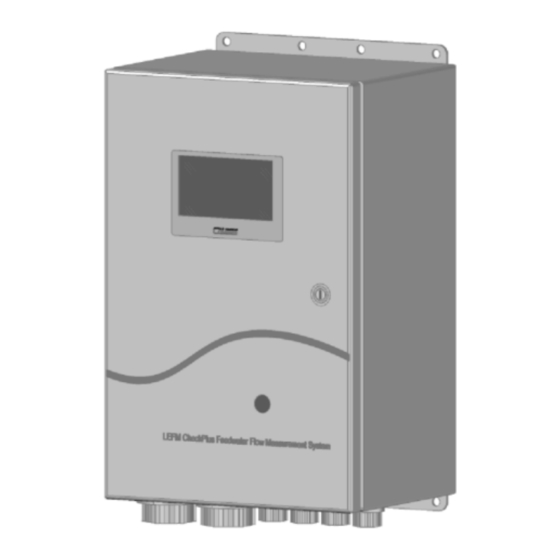
LEFM CheckPlus-C Transmitter User Manual IB0919 Rev. 5 LEFM CheckPlus-C Specifications 1.2.1 LEFM CheckPlus-C Transmitter Material: NEMA 4X Stainless Steel NEMA 4 Painted Carbon Steel Wall Mount Net Weight: 35 lbs. (15.9 kg) (See Figure 2-1 for dimensions) Power Requirements Voltage Supply Required: 120 VAC, 50/60 Hz or, 230 VAC, 50/60 Hz Current Draw:... -
Page 10: Environment
IB0919 Rev. 5 LEFM CheckPlus-C Transmitter User Manual 1.2.2 Environment Indoor or Outdoor Use Altitudes up to 3000 meters Pollution – Degree 2 Power Supply ±10% of nominal voltages Storage Temperature Transducer Cable: Transmitter: -70°F (-57°C) to 158 ° F (70°C) Operating Temperatures Transmitter: -40°F (-40°C) to 140°F (60°C) -
Page 11: Installation
LEFM CheckPlus-C Transmitter User Manual IB0919 Rev. 5 INSTALLATION The exact physical properties, acoustic properties, and calibration of the metering section are programmed into the transmitter as part of the commissioning activities. When installing multiple units ensure that the transmitter is properly associated with the intended metering section and measurement plane. Transmitter and Terminations The LEFM CheckPlus-C meter is designed to be used under a wide variety of environmental conditions. -
Page 12: Rs-485 Communication
IB0919 Rev. 5 LEFM CheckPlus-C Transmitter User Manual 2.1.2 Field Terminations The wiring should be routed to the transmitter in shielded conduit that meets site environment specifications. All terminations should be made according to Table 2-1 through Table 2-6. For full environmental temperature range, all wiring (conductors) into and out of the transmitter should be rated as follows: ... - Page 13 LEFM CheckPlus-C Transmitter User Manual IB0919 Rev. 5 Figure 2-1: Transmitter Enclosure (units in inches, [mm]) February 2014 Page 9 Installation...
- Page 14 IB0919 Rev. 5 LEFM CheckPlus-C Transmitter User Manual On/Off Breaker RS-485 Power Digital I/O Analog I/O Transducers See Figure 2-2A Figure 2-2: Electronics with Door Open Circuit Breaker – ON to the LEFT, OFF to the RIGHT Installation Page 10 February 2014...
- Page 15 LEFM CheckPlus-C Transmitter User Manual IB0919 Rev. 5 Jumper “2” wire – RS485 “4” wire – RS485 E1 (pins 1&2) E1 (pins 3&2) E2 (pins 1&2) E2 (pins 3&2) Indicates Unit Operating Power Supply Check ± 12Vdc ± 5 Vdc Top View Figure 2-2A –...
- Page 16 IB0919 Rev. 5 LEFM CheckPlus-C Transmitter User Manual Transducer Cable Identification Transmitter Termination Wire Name Device Terminal 1 UP Shield Shield 3 UP Shield 4 UP Shield 1 DN Shield 2 DN Shield 3 DN Shield 4 DN Shield 5 UP Shield 6 UP Shield...
- Page 17 LEFM CheckPlus-C Transmitter User Manual IB0919 Rev. 5 RTD Connections 0, 4-20mA Connection Analog Input Source Description Terminus Description Terminus 0, 4-20mA + TB4-1 Analog Input 1 0, 4-20mA - TB4-2 Shield TD4-3 0, 4-20mA + TB4-7 Analog Input 2 0, 4-20mA - TB4-8 Shield...
- Page 18 IB0919 Rev. 5 LEFM CheckPlus-C Transmitter User Manual Power Description Terminus Connectivity LINE Power-1 120 VAC Neutral Power-2 Ground/Earth Power-3 +24 VDC Power-1 24 VDC 24 VDC Return Power-2 Ground/Earth Power-3 LINE 1 Power-1 240 VAC LINE 2 Power-2 Ground/Earth Power-3 Table 2-5: Power Connections (Only one type of power should be connected)
-
Page 19: Meter Installation Check-Out
LEFM CheckPlus-C Transmitter User Manual IB0919 Rev. 5 2.2 Meter Installation Check-Out The following steps are recommended to checkout a meter’s installation. See Section 5 troubleshooting and maintenance. Also reference Cameron procedure EFP-68. Step 1: Verify all field terminations have proper continuity and isolation from each other and earth. Verify connections are good with respect to insulation. -
Page 20: Operational Overview
IB0919 Rev. 5 LEFM CheckPlus-C Transmitter User Manual OPERATIONAL OVERVIEW Measuring Velocities LEFM Ultrasonic Flow Meters use pairs of ultrasonic transducers to send acoustic pulses to one another along a measurement path. The measurement path is at an angle to the fluid flow. The acoustic pulse’s transit time depends upon both the velocity of sound (VOS) in the fluid and the velocity of the fluid along the path. -
Page 21: Measuring Flowrate
LEFM CheckPlus-C Transmitter User Manual IB0919 Rev. 5 When pulses travel upstream and downstream during the same time, the above equations may be treated as simultaneous, and solved for the two unknowns, C and V and taking into account path angle Solving for V ... -
Page 22: Lefm Checkplus-C Transmitter
IB0919 Rev. 5 LEFM CheckPlus-C Transmitter User Manual 3.3 LEFM CheckPlus-C Transmitter The LEFM CheckPlus-C Transmitter contains four major functional units, the digital board (CTC), the analog board (MXR), the Backplane where all wiring connections are made, the IOB which handles all inputs and outputs from the installation site and has protection circuitry, and the power supply. -
Page 23: Operation
LEFM CheckPlus-C Transmitter User Manual IB0919 Rev. 5 4.0 OPERATION 4.1 Definitions SNR – Signal to Noise Ratio Gain – Required gain to amplify signal Rejects – Percentage of data rejected by one or more of the System Quality Tests VOS –... -
Page 24: Display
IB0919 Rev. 5 LEFM CheckPlus-C Transmitter User Manual 4.3 Display The transmitter has a graphics display. The display shows the meter’s indicated flow, totalized flow, fluid properties, and diagnostics data. The transmitter repeatedly cycles through all display parameters. The display provides information for each of the meter’s paths. The display cycle when in Normal Mode is shown below in Figure 4-1: Figure 4-1: Display Screens in Normal Operation Display 1... -
Page 25: Boot Up And Normal Operational Screens
LEFM CheckPlus-C Transmitter User Manual IB0919 Rev. 5 4.3.1 Boot up and Normal Operational Screens On power up and boot up, a “splash screen” will appear displaying the part number and the checksum for the executable program (see below). Approximately 5 seconds after powering on the transmitter, the following Main Display screen appears displaying the total accumulated volume and the current flow rate. - Page 26 IB0919 Rev. 5 LEFM CheckPlus-C Transmitter User Manual The second screen in the display cycle contains acoustic path diagnostic data. Information for Paths 5-8 (for an eight path meter only) will be displayed on the next cycle through the screens. Display 2 - Acoustic Path Diagnostic Data (Four Paths at a Time) The third screen to appear displays Meter level diagnostic data.
- Page 27 LEFM CheckPlus-C Transmitter User Manual IB0919 Rev. 5 Following Display 3, the Main Display screen will be displayed and repeat three times. Next will follow the first Fluid Properties screen which displays Density and Velocity of Sound (VOS). Density Units are user defined Velocity Units are user defined...
-
Page 28: Path Level Alarm Display Screens
IB0919 Rev. 5 LEFM CheckPlus-C Transmitter User Manual 4.3.2 Path Level Alarm Display Screens When in a Path Level Alarm condition, Display 6 will replace Display 1 (the displays will continue to cycle as in Figure 4-1). The display will contain alarm data on the bottom for each path and will alternate between displaying a flow or a totalizer value at the top. - Page 29 LEFM CheckPlus-C Transmitter User Manual IB0919 Rev. 5 Figure 4-2: Display Screens in Meter State Alarm Mode Display 6 (Alarm) Main Display Flow or Total and Alarm Display 3 Meter State Time, Status, A/I (Repeat 3 times) Display 2 Display 4 Path Diagnostics Fluid Properties SNR, Gain, Rej, Alarm...
-
Page 30: Output Test Mode
IB0919 Rev. 5 LEFM CheckPlus-C Transmitter User Manual Note that Display 2 will only display four path’s information at one time. The first time through the display cycle, Paths 1-4 will be displayed; the second time, Paths 5-8 (for an eight path meter only) will be displayed. -
Page 31: Switch Forced Setup
LEFM CheckPlus-C Transmitter User Manual IB0919 Rev. 5 4.6 Switch Forced Setup If CTC dip switch SW1-8 (see Table 5-2) is set in the UP position during boot-up, the transmitter will wait for a new setup file to be sent before running. While waiting for a new setup file, the transmitter’s communication parameters will default to a baud rate of 9600 and a Modbus address of “1”. -
Page 32: Maintenance
IB0919 Rev. 5 LEFM CheckPlus-C Transmitter User Manual MAINTENANCE WARNING: NO OPERATOR ACCESS IS PERMITTED IN THE UNIT. SERVICE SHOULD ONLY BE PERFORMED BY QUALIFIED PERSONNEL. Introduction This section provides procedures for troubleshooting and maintenance tasks which personnel can perform on the LEFM CheckPlus-C Transmitter and meter body. -
Page 33: Internal Electronics Inspection
LEFM CheckPlus-C Transmitter User Manual IB0919 Rev. 5 f. Inspect enclosure mounting and fastening hardware. 5.2.2 Internal Electronics Inspection a. If necessary, remove power to the LEFM CheckPlus-C by opening circuit breaker CB1. b. Put on an ESD (Electrostatic Discharge) protective wrist strap. Connect ESD protective wrist strap to a known ground;... -
Page 34: Power Supply Voltage Troubleshooting And Maintenance
IB0919 Rev. 5 LEFM CheckPlus-C Transmitter User Manual 5.3 Power Supply Voltage Troubleshooting and Maintenance I/O LED – Red -- Off When Normal CTC LED –Red -- Off When Normal MXR LED – Red -- Off When Normal RS-485 Selection: Power Supply LED –... -
Page 35: Ctc Troubleshooting And Maintenance
LEFM CheckPlus-C Transmitter User Manual IB0919 Rev. 5 The following table provides the specified backplane voltage. Terminal Name Requirement TB9-1 5 Volts 5 ±0.1 Volts TB9-2 +12 Volts +12 ±0.5 Volts TB9-3 -12 Volts -12 ±0.5 Volts TB9-4 Ground Electrical Ground, 0V Table 5-1: Required Backplane Test Voltages 5.4 CTC Troubleshooting and Maintenance Red Light On... - Page 36 IB0919 Rev. 5 LEFM CheckPlus-C Transmitter User Manual The CTC has DIP switches that can be used to control the board. Typically, the only one ever needed is DIP Switch number 8. This is used if the configuration has been corrupted, putting the CTC into a safe state to have a new setup sent.
-
Page 37: Mxr Troubleshooting And Maintenance
LEFM CheckPlus-C Transmitter User Manual IB0919 Rev. 5 5.5 MXR Troubleshooting and Maintenance Fuse, F3 0.125 Amp +150V Fuse, F2 Top View 0.5 Amp -12V TP = +150V Fuse, F1 TP = -150V 0.5 Amp +12V Figure 5-3: MXR Fuse Location February 2014 Page 33 Maintenance... -
Page 38: Iob Troubleshooting And Maintenance
IB0919 Rev. 5 LEFM CheckPlus-C Transmitter User Manual 5.6 IOB Troubleshooting and Maintenance Figure 5-4A: IOB Fuse Location – Top View Figure 5-4B: IOB Fuse Location – Rear View Maintenance Page 34 February 2014... -
Page 39: Analog Input/Output Verification Procedure
LEFM CheckPlus-C Transmitter User Manual IB0919 Rev. 5 Rating Fuse Side Purpose (mA) Front Analog Input Back Analog Input Front Analog Output Back Analog Output Front RS485 A1 Back RS485 B1 Front RS485 Y1 Back RS485 Z1 Front RS485 A2 Back RS485 B2 Front... -
Page 40: Analog Inputs
IB0919 Rev. 5 LEFM CheckPlus-C Transmitter User Manual 5.7.1 Analog Inputs Step 1: Connect the test equipment as follows: Current Inputs 0-20 mA Source (DC Calibrator) Output 1 2 3 4 5 6 Analog In Terminal Block BPL-TB4 RTD Calibrator RTD Inputs High 1 2 3 4... - Page 41 LEFM CheckPlus-C Transmitter User Manual IB0919 Rev. 5 Refer to Table 5-3 for the specific connection terminals on EUA. Analog Input Positive Negative Channel Excitation Terminal Terminal Excitation BPL-TB4-1 BPL-TB4-2 BPL-TB3-2 BPL-TB3-4 BPL-TB3-1 BPL-TB3-3 Analog Output Positive Negative Channel Terminal Terminal BPL-TB4-4 BPL-TB4-5...
-
Page 42: Rtd Inputs
IB0919 Rev. 5 LEFM CheckPlus-C Transmitter User Manual 5.7.2 RTD Inputs Step 1: Connect the RTD calibrator as shown in Figure 5-5. Using LEFM Link, scale the analog inputs according to the specific RTD used. Using the RTD Calibrator, input five temperatures (equally separated and covering the range of the module). -
Page 43: Analog Input Verification
LEFM CheckPlus-C Transmitter User Manual IB0919 Rev. 5 5.8 Analog Input Verification The LEFM may have an analog input (for example, temperature, pressure, or density). The input signal is conditioned before it is converted to a digital input. The input is scaled linearly to convert the user input of 4-20 mA (or 0-20 mA) to maximum and minimum values. -
Page 44: Metering Section And Transducer Cables
IB0919 Rev. 5 LEFM CheckPlus-C Transmitter User Manual Table 5-7—Digital Output Voltage Jumper Positions Jumper Voltage Position 5.10 Metering Section and Transducer Cables 5.10.1 Metering Section Inspection Some steps in this procedure may require handling components at temperatures approaching 500°F (260°C) - if performed when the power plant is operating. Use insulated gloves to perform this procedure. -
Page 45: Transducers
LEFM CheckPlus-C Transmitter User Manual IB0919 Rev. 5 Verify each transducer cable has not suffered any damage. Check connectors on cables at each end to verify each is undamaged. Clean connector with electronic contact cleaner if fouled or corroded. Replace any damaged cable or connector. Disconnect transducer cables from metering section. - Page 46 IB0919 Rev. 5 LEFM CheckPlus-C Transmitter User Manual Transducer Couplant Transducer Spacer Compression Screw Transducer Housing is welded into the Spool piece Metering Section Figure 5-7: Transducer Assembly Construction Outline Maintenance Page 42 February 2014...
-
Page 47: Troubleshooting And Diagnostics For The Ultrasonics
LEFM CheckPlus-C Transmitter User Manual IB0919 Rev. 5 TROUBLESHOOTING AND DIAGNOSTICS FOR THE ULTRASONICS Diagnostics The LEFM CheckPlus-C Transmitter interfaces via a serial port to external devices. The Transmitter uses the Modbus protocol. Cameron provides PC (laptop) software (LEFM Link) and the LEFM CheckPlus-C CPU HMI to interface with the Transmitter via Modbus. -
Page 48: Meter Troubleshooting
IB0919 Rev. 5 LEFM CheckPlus-C Transmitter User Manual 6.3 Meter Troubleshooting The following codes are used to indicate the Meter State alarms as shown on the Meter State Screen (reference Display 3 – Section 4.4.3): Alarm Description Display Code Modbus Code Normal All path are operating normally Internal... -
Page 49: Path Failure
LEFM CheckPlus-C Transmitter User Manual IB0919 Rev. 5 6.3.3 Path Failure This alarm identifies that a path level alarm exists. See Section 6.4 for path level alarm details. 6.3.4 Clock Failure The MXR board contains two highly accurate oscillators used in the timing and signal processing. A 100 MHz clock is used to measure the acoustic path timing (TDown and Tup) while a 5 MHz clock controls the path to path timing, range-gating, and other signal processing functions. -
Page 50: Path Reject Status
IB0919 Rev. 5 LEFM CheckPlus-C Transmitter User Manual 6.4.1 Path Reject Status When the path status indicates that the Reject Test failed, it indicates that the percentage of data that has been rejected has exceeded the LEFM CheckPlus-C System thresholds. The following troubleshooting sequence can be followed to pinpoint the root cause. - Page 51 LEFM CheckPlus-C Transmitter User Manual IB0919 Rev. 5 If an acoustic signal does not exist, or if SNR has degraded from installation, then follow checklist below: Verify the pipe is full of liquid. Check the impedance of the transducer cable. If cable impedance is less than 10 Megohms, then replace/repair cable.
-
Page 52: Calculation Error
IB0919 Rev. 5 LEFM CheckPlus-C Transmitter User Manual If the transducer signal strength has decreased, or the level of coherent or random noise has increased, from the time of commissioning or last service a failure of that transducer path may be impending. Being able to measure and record these values is important. -
Page 53: Velocity Outlier
LEFM CheckPlus-C Transmitter User Manual IB0919 Rev. 5 If there has been a change in plant hydraulics or operation, for example, an upstream heater has been taken off-line, than a VOS failure may occur. If this is the cause, an engineering analysis is required before the threshold or default ratios are changed. -
Page 54: Reprogramming The Transmitter
IB0919 Rev. 5 LEFM CheckPlus-C Transmitter User Manual 6.5 Reprogramming the Transmitter While it is not likely, there may be a time that the transmitter may need to be reprogrammed. This would typically occur when a CTC Board has been replaced with an inventory item, not specifically assigned to a given metering section. -
Page 55: Recommended Spare Parts
LEFM CheckPlus-C Transmitter User Manual IB0919 Rev. 5 7.0 RECOMMENDED SPARE PARTS Qty: 5 Littelfuse – 125mA fast acting (FF) – Cameron PN: 9A-154.125 Qty: 1 Littelfuse – 2000mA fast acting (FF) – Cameron PN: 9A-154.002 Qty: 2 Littelfuse – 500mA fast acting (FF) – Cameron PN: 9A-154.500 Qty: 1 CTC Board –... - Page 56 Seller will pass only through to its purchaser of such items the warranty granted to it by the manufacturer. Sensia LLC 200 Westlake Park Blvd...
Need help?
Do you have a question about the CALDON LEFM CheckPlus-C and is the answer not in the manual?
Questions and answers