
Subscribe to Our Youtube Channel
Related Manuals for Sensia TA-1000 Plus


Summary of Contents for Sensia TA-1000 Plus
- Page 1 Valves & Measurement LI N CO TA-1000 Plus Temperature Averager Hardware User Manual Manual No. 50258174, Rev. 02...
- Page 2 Symbols Marked on Equipment Attention! Refer to manual Protective (earth) ground *Mark of Sensia. Other company, product, and service names are the properties of their respective owners. Copyright © 2021 Sensia All rights reserved. Manual No. 50258174, Rev. 02 November 2016...
-
Page 3: Table Of Contents
Wiring Diagrams for Bottom Circuit Board (EXP) ..................... 26 Wiring Diagrams for Top Circuit Board (EXP) ....................27 Section 4—Configuring and Resetting the TA-1000 Plus ................29 Table 4.1—Display Readouts (default) ...................... 29 Table 4.2—Analog Input Readouts (optional) .................... 29 Table 4.3—Volume Correction Readouts (compensated volume option) .......... - Page 4 Replacing the Bottom Circuit Assembly ..................... 52 Troubleshooting ..............................54 Weatherproof Package ..........................55 Explosion-proof Package ........................... 57 Section 6—Spare Parts ..........................59 Table 6.1—TA-1000 Plus Spare Parts ....................... 59 Appendix A—TA-1000 Plus Protocol ......................A-1 Introduction ..............................A-1 Supported Commands.............................A-1 Data Types ..............................A-2 Registers .................................A-2...
-
Page 5: Section 1-Introduction
Two fail-safe relay output contacts provide an alarm if a temperature probe fails, a temperature is outside the acceptable range, the processor fails or power is seriously depleted or cut off. If the TA-1000 Plus is equipped with analog inputs, the relay output will also signal an out-of range input. If equipped with a net pulse output option, the device can be used to transmit a compensated volume to another device. -
Page 6: Display
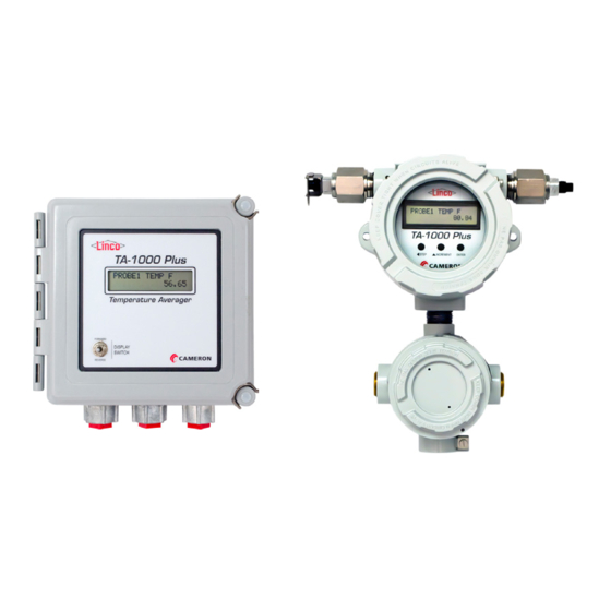
The terminal housing must be installed at the factory. The addition of a terminal housing to an existing device violates CSA certification regulations. Figure 1.2— TA-1000 Plus explosion-proof package with optional terminal housing Display The display provides a real-time readout of process temperature (measured by the probe), average tempera- ture, total counts, counts per hour and alarm count. -
Page 7: Optional I/O
TA-1000 Plus Temperature Averager Section 1 Temperature The temperature input is a single-element probe sold by Cameron. The dual-channel TA-1000 Plus device will accept inputs from two probes. Flow Flow input pulses may be 9–30 VDC pulses, 120 VAC pulses or dry contact closures. -
Page 8: Product Identification
Section 1 TA-1000 Plus Temperature Averager sure can be brought into the TA-1000 Plus using an optional analog input. The correction calculation uses API MPMS Chapter 11.1 to calculate the volume correction factor (VCF) of crude oil using the entered API gravity and average temperature, for a temperature base of 60°F and a pres- sure base of 14.73 psia. - Page 9 TA-1000 Plus Temperature Averager Section 1 Table 1.1—TA-1000 Plus Specifications Category Description Specification Weight Explosion-proof 5.2 lb Explosion-proof with 8.1 lb Optional Terminal Housing Weatherproof 3.2 lb System Power 120 VAC, 50/60 Hz @ 250 mA 8–30 VDC @ 200 mA Operating Temperature -40°F to 158°F (-40°C to 70°C)
- Page 10 Section 1 TA-1000 Plus Temperature Averager Table 1.1—TA-1000 Plus Specifications Category Description Specification I/O, Standard Temperature Probe Input Quantity: 1 per channel (2 possible) Supports single-element thermistor probe Operating Temperature: -40°F to 257°F (-40°C to 125°C) Accuracy ±0.15°F (± 0.08°C)
- Page 11 TA-1000 Plus Temperature Averager Section 1 Table 1.1—TA-1000 Plus Specifications Category Description Specification I/O, Optional Analog Outputs Quantity: 1 or 2 (customer choice) Configurable for transmitting a live probe temperature, an average temperature or an analog input value (in devices equipped with analog inputs) Type 4–20 mA, optically-isolated, externally powered...
- Page 12 Section 1 TA-1000 Plus Temperature Averager This page is left blank intentionally.
-
Page 13: Section 2-Installing The Ta-1000 Plus (Weatherproof)
4. Have you considered temperature transmission distance when selecting wiring size? Temperature probes may be located up to 1200 feet away from the TA-1000 Plus. Distances of up to 500 feet require 18 to 20 AWG wire. Distances of 500–1200 feet require 16 AWG wire. -
Page 14: Weatherproof Package Mounting Options
Section 2 TA-1000 Plus Temperature Averager Weatherproof Package Mounting Options The TA-1000 Plus can be panel-mounted with the mounting hardware supplied or pole-mounted with an op- tional pole-mount kit (see Section 6—Spare Parts, Page 59 for ordering information). 6.50 in. -
Page 15: Panel-Mounting The Device
The weatherproof TA-1000 Plus can be mounted to a 2-inch pole with an optional pole-mount kit (includes two panels, four screws and two U-bolts). To install the TA-1000 Plus on a vertical pole, perform the follow- ing steps (dimensions provided in Figure 2.5, Page... - Page 16 Section 2 TA-1000 Plus Temperature Averager Figure 2.4—Brackets for mounting weatherproof TA-1000 Plus to vertical pipe 2.88 in. (73.2 mm) 10.32 in. (262.1 mm) 9.52 in. (241.8 mm) 4.38 in. 3.25 in. (111.3 mm) (82.6 mm) 6.91 in. (175.5 mm)
-
Page 17: Weatherproof Package Field Wiring Connections
National Electric Codes and should conform to all local code requirements. All field wiring enters the weatherproof TA-1000 Plus through three conduit hubs in the bottom of the enclo- sure and connects to the circuit assembly inside. Unused hub entries should be plugged, as shown in Figure 2.6. - Page 18 7. Route a protective earth grounding conductor into the enclosure with the incoming power conductors to ground the TA-1000 Plus in accordance with national and local electrical codes. Connect the ground wire to the internal ground lug located just below the circuit board on the support bracket (see Figure 2.7).
-
Page 19: Wiring Diagrams (Wp)
PULSE PULSE PULSE PULSE CONTACT CONTACT INPUT 1 INPUT 2 INPUT 1 INPUT 2 INPUT 1 INPUT 2 LINE N RELAY AC PULSE INPUT DC PULSE INPUT CONTACT (120 VAC) (9–30 VDC) Figure 2.8—Wiring diagrams for TA-1000 Plus, weatherproof package... -
Page 20: Wiring Diagrams For Optional I/O (Wp)
4-20 mA transmitter. TRANSMITTER TRANSMITTER ANALOG OUTPUT ANALOG ANALOG OUTPUT 1 OUTPUT 2 OPERATING ANALOG READOUT REGION (Resistor may be included.) 24 30 LOOP SUPPLY VOLTAGE (VDC) 9–30 VDC POWER SUPPLY Figure 2.9—Wiring diagrams for TA-1000 Plus, weatherproof package, optional inputs/outputs... -
Page 21: Section 3-Installing The Ta-1000 Plus (Explosion-Proof)
4. Have you considered temperature transmission distance when selecting wiring size? Temperature probes may be located up to 1200 feet away from the TA-1000 Plus. Distances of up to 500 feet require 18–20 AWG wire. Distances of 500–1200 feet require 16 AWG wire. - Page 22 Section 3 TA-1000 Plus Temperature Averager 10.33 in. (262.34 mm) 5.85 in. 5.69 in. (148.69 mm) (144.53 mm) Figure 3.1—Typical explosion-proof package dimensions 10.33 in. (262.34 mm) 11.53 in. (292.86 mm) 5.79 in. (147.07 mm) 7.12 in. (180.85 mm) 5.69 in.
-
Page 23: Panel-Mounting The Device
Figure 3.3—Explosion-proof TA-1000 Plus showing location of mounting ears Installing on Vertical Pipe To mount the explosion-proof TA-1000 Plus using the optional pole-mount kit (includes metal bracket, 2 U- bolts, 2 bolts and 2 nuts), perform the following steps: 1. Connect the mounting bracket to the TA-1000 Plus using the two bolts provided. -
Page 24: Explosion-Proof Package Field Wiring Connections
National Electric Codes and conform to all local code requirements. Field wiring enters the explosion-proof TA-1000 Plus through the bottom conduit opening or through the con- duit openings in the optional terminal housing and connects to the circuit boards inside. - Page 25 (Figure 3.5). Alternatively, connect an earth ground conductor to the external stainless steel ground lug on the TA-1000 Plus explosion-proof enclosure and to a ground rod or other suitable system earth ground. Connect the flowmeter or pulse input wiring. For an AC or DC pulse input, use TB12. For a dry- contact input, use TB13.
-
Page 26: Wiring Diagrams For Bottom Circuit Board (Exp)
RELAY OUTPUT 2 PULSE PULSE PULSE PULSE COM2 INPUT 1 INPUT 2 INPUT 1 INPUT 2 COM1 LINE N RELAY AC PULSE INPUT DC PULSE INPUT CONTACTS (120 VAC) (9–30 VDC) Figure 3.6—Wiring diagrams for explosion-proof TA-1000 Plus bottom circuit board... -
Page 27: Wiring Diagrams For Top Circuit Board (Exp)
4-20 mA TRANSMITTER TRANSMITTER ANALOG OUTPUT ANALOG ANALOG OUTPUT 1 OUTPUT 2 ANALOG READOUT (Resistor may be OPERATING REGION included.) 24 30 9–30 VDC LOOP SUPPLY VOLTAGE (VDC) POWER SUPPLY Figure 3.7—Wiring diagrams for explosion-proof TA-1000 Plus top circuit board... - Page 28 Section 3 TA-1000 Plus Temperature Averager This page is left blank intentionally.
-
Page 29: Section 4-Configuring And Resetting The Ta-1000 Plus
The parameters displayed will vary with the type of device (single or dual channel) and options purchased. Every TA-1000 Plus will display four readings and two reset readouts for each probe input enabled (Table 4.1). -
Page 30: Viewing Parameters
Note If an optional terminal housing is purchased with a TA-1000 Plus, a user can relocate the display switch to a different conduit entry. If the display switch location is changed, the instructions attached to the lid that refer to switch locations will no longer be accurate. -
Page 31: Configuring The Device
TA-1000 Plus Temperature Averager Section 4 Configuring the Device Configuration Menus Configuration menus are accessed with three buttons—STEP, INCREMENT and ENTER. These buttons will be referenced repeatedly in the following configuration procedures. In the weatherproof package, the three configu- ration buttons—STEP, INCREMENT and ENTER—are located near the center of the... -
Page 32: Configuring Modbus Communications
Press ENTER to advance to the Baud Rate 2 selection menu (Figure 4.4, Page 33). 5. From the Baud Rate 2 selection, press INCREMENT to select the desired baud rate. the TA-1000 Plus supports a baud range of 300 to 38.4 kbps. Note... -
Page 33: Configuring Analog Inputs
Analog inputs are optional features. The following procedure pertains only to devices purchased with this op- tion. The TA-1000 Plus supports up to two analog inputs. Each can be configured for a 0–5 VDC, 1–5 VDC or 4–20 mA signal and can be used to receive readings from a pressure transmitter, densitometer or BS&W de- tector. - Page 34 If the BS&W live reading goes above the divert setpoint value or goes outside the configured range, the TA-1000 Plus’ delay timer will be activated. If the value remains out of tolerance at the end of the delay period, flow will be diverted to a holding tank, flow loop, etc. If the value comes back inside the tolerance and remains there for 1/10th of the configured delay period (for example, 9 seconds when the time delay is set for 90 seconds), the divert valve will close and the timer will stop.
- Page 35 TA-1000 Plus Temperature Averager Section 4 Pressure Input When the device is equipped with the compensated volume/net pulse output option, a pressure input can be used to compensate a flow volume back to standard conditions in accordance with the API MPMS Chapter 11.1 standard.
-
Page 36: Enabling Volume Compensation
60° F. If pressure and temperature compensation is desired, a live pressure can be brought into the TA-1000 Plus using an optional analog input. The correction calculation uses API MPMS Chapter 11.1 to calculate the volume correction factor (VCF) of crude oil using the entered API gravity and average temperature, for a temperature base of 60°F and a pres-... -
Page 37: Configuring Outputs
Digital Output The TA-1000 Plus is equipped with two mechanical SPDT relays that can be configured for use as an alarm or as a means of diverting flow when the TA-1000 Plus is used for BS&W monitoring. TA-1000 Plus alarms may be activated by probe or probe wiring failure, faulty temperature circuitry or an out-of-range measure- ment. -
Page 38: Configuring A Custom Probe Fail Alarm
By default, a probe fail alarm is generated when the process fluid temperature falls below or rises above the probe operating range. However, some applications require the user to take action before the temperature reaches these levels. The TA-1000 Plus allows the user to determine custom low and high setpoints for trig- gering a fail alarm. -
Page 39: Custom Fail Alarms
TA-1000 Plus Temperature Averager Section 4 separate out in a holding tank as the temperature cools. The ability to establish an alarm when the process fluid is approaching the paraffin melting point allows the user to better manage this risk. -
Page 40: Disabling The Pulse Input Filter
Disabling the Pulse Input Filter The TA-1000 Plus contains two built-in noise filters that improve the accuracy of counts in systems where pulses are generated less than once per second. If pulses are generated faster than once per second, however, performance may be improved by disabling the filter as follows: 1. -
Page 41: Resetting Probe Totals, Alarms And Input Averages
TA-1000 Plus Temperature Averager Section 4 4. Press INCREMENT to change the PulseIn1 Filter setting to “Disable.” 5. Press ENTER to accept the change and advance to the PulseIn2 Filter menu. Again, the bottom readout should display the default setting, “Enable.”... -
Page 42: Resetting Probe Totals
5. The display should indicate “0” to verify the alarm is cleared. Clearing Input Averages When analog inputs are enabled, the TA-1000 Plus will continuously average input values and display those averages. It is recommended that these values be zeroed each time the user resets the probe counts and totals. -
Page 43: Securing The Device After Reset
Appendix D—Installing the Weatherproof Custody Transfer Lockout Kit, Page D-1 for ordering and installation information. Explosion-proof Package To secure the explosion-proof TA-1000 Plus, depress the reset switch slightly and slide the metal tab of the custody transfer lockout over the switch (Figure 4.14). Secure with a customer-supplied lock. - Page 44 Section 4 TA-1000 Plus Temperature Averager This page is left blank intentionally.
-
Page 45: Section 5-Ta-1000 Plus Maintenance
Obtaining Technical Assistance Knowing which functions are enabled in a TA-1000 Plus is key to a Cameron technician’s ability to trouble- shoot a suspected malfunction. Enabled functions are identified by a factory-programmed function ID, which is easily retrieved from the device if the processor and display are functioning. Before contacting Cameron to report a suspected malfunction, please retrieve your device’s Function ID as follows:... - Page 46 Section 5 TA-1000 Plus Temperature Averager Figure 5.2—Weatherproof circuitry 3. Disconnect the SATA cable connecting the circuit board to the display assembly by depressing the metal clip on the right side of the cable connector (Figure 5.3). Figure 5.3—SATA cable clip 4.
- Page 47 TA-1000 Plus Temperature Averager Section 5 12. Plug the display switch into TB1 on the circuit board. 13. Reconnect the SATA cable to J2 on the circuit board. 14. Close the enclosure door, secure the latches and restore power to the device.
-
Page 48: Display Replacement-Weatherproof
Replacing the Top Circuit Assembly The explosion-proof TA-1000 Plus includes two circuit board assemblies. The top circuit assembly includes an LCD board and a circuit board containing probe input, analog input/output and communications connec- tions. - Page 49 TA-1000 Plus Temperature Averager Section 5 Mounting screw (1 of 2) Figure 5.6—Location of mounting screws 4. To access the circuit board connections, lift out the top circuit assembly and lay it flat with the display facing downward, as shown in Figure 5.7.
- Page 50 Section 5 TA-1000 Plus Temperature Averager Figure 5.8—Top circuit assembly Figure 5.9—Separation of faceplate from top circuit assembly 8. Unplug the terminal blocks from the top circuit board and discard the assembly. 9. Align the faceplate removed in Step 7 with the new top circuit assembly so that the cutout frames the LCD display and the three round holes fit over the black buttons as shown in Figure 5.10, Page...
- Page 51 TA-1000 Plus Temperature Averager Section 5 13. With the display facing upward, reposition the assembly on top of the standoffs shown in Figure 5.12 that the standoffs on the left and right align with the mounting holes in the top circuit assembly.
-
Page 52: Replacing The Bottom Circuit Assembly
16. Close the enclosure door, secure the latches and restore power to the device. Replacing the Bottom Circuit Assembly The explosion-proof TA-1000 Plus includes two circuit board assemblies. The bottom circuit assembly in- cludes an AC/DC converter and power, pulse input, contact input and digital (relay) output connections. Fac- tory-wired connections for the display switch and reset switch are also on this board. - Page 53 TA-1000 Plus Temperature Averager Section 5 Display Reset switch switch Loosen screws to unplug Figure 5.14—Display switch and reset switch locations Mounting screw (1 of 4) Ribbon cable latch Figure 5.15—Bottom circuit board showing location of mounting screw and ribbon cable latch...
-
Page 54: Troubleshooting
Section 5 TA-1000 Plus Temperature Averager 11. Tighten the standoffs in the back of the enclosure (Figure 5.17). Standoff (1 of 4) Figure 5.17—Empty explosion-proof enclosure showing standoff locations 12. Place the new bottom circuit assembly into the enclosure with the straight side of the circuit board at the top of the enclosure, resting just below the ground screw and secure with the screws removed in Step 7. -
Page 55: Weatherproof Package
“F4”. If the fuse is open, replace it with an approved 5×20 mm, 1 amp, 250 VAC rated fuse. Only the following fuses are approved for use with the TA-1000 Plus: LIT- TELFUSE Part No. 0215001.HXP and BEL FUSE INC. Part No. 5HT 1-R. Cameron also supplies these approved fuses. - Page 56 Section 5 TA-1000 Plus Temperature Averager Symptom Corrective Action(s) Counts Do Not Advance On channel 1, place a voltmeter across Terminals 1 and 2 (PUL IN 1) of terminal block with Flow (DC Pulse TB12. For DC pulse operation on channel 2, place the voltmeter across Terminals 3 and 4 (PUL IN 2) of the same terminal block.
-
Page 57: Explosion-Proof Package
“F4”. If the fuse is open, replace it with an approved 5×20 mm, 1 amp, 250 VAC rated fuse. Only the following fuses are approved for use with the TA-1000 Plus: LITTEL- FUSE Part No. 0215001.HXP and BEL FUSE INC. Part No. 5HT 1-R. Cameron also supplies these approved fuses. - Page 58 If the counts are higher than normal, the cause may be noise generated from external high current devices. If counts are high and the pulse input to the TA-1000 Plus is from an AC control panel, the pulses may be cycled erroneously each time the unit is stopped and started.
-
Page 59: Section 6-Spare Parts
Pipe Plug, 3/4-14 NPT, 10 mm Hex Socket, Brass, Explosion-proof Weatherproof Enclosure 50262916 Display Switch with Cable Assembly, Weatherproof 2350798-01 Display Assembly and SATA Cable, TA-1000 Plus, Weatherproof Contact Cameron Circuit Assembly, TA-1000 Plus, Main Board, Weatherproof 50275693 Kit, Pole Mount, TA-1000 Plus, Weatherproof 9A-100001795 Conduit Hub, 1/2 in., Weatherproof... - Page 60 Section 6 TA-1000 Plus Temperature Averager This page is blank intentionally.
-
Page 61: Appendix A-Ta-1000 Plus Protocol
Register Table Version: 1 Introduction The communications protocol for the TA-1000 Plus is in accordance with Modicon, Inc. RTU Mode Modbus as described in Modicon Modbus Protocol Reference Guide, PI-MBUS-300 Rev. J, June 1996. All registers are implemented as 4X or holding registers. Reading of registers is implemented via function code 03H (Read Holding Registers). -
Page 62: Data Types
Appendix A TA-1000 Plus Temperature Averager Data Types Various data types are implemented in the TA-1000 Plus. The following table lists the formats and the num- bers of bytes and registers associated with each type: Data Type Byte Count Register Count... -
Page 63: Product Code
0x03EE Serial Number Low Product Code The Product Code is a read-only parameter used for identifying a TA-1000 Plus device. This parameter is de- fined at the factory. Firmware Version/Register Table Version The Firmware Version and Register Table Version numbers are set by the factory and are read-only. To de- termine the version number, read the appropriate register and divide the value by 100. - Page 64 Appendix A TA-1000 Plus Temperature Averager Communications Configuration Register Register Data (Decimal) (Hex) Description Type Access Default 1100 0x044C Port 1 – Port Usage 0 = Slave 1101 0x044D Port 1 –Slave Address [1–65535, excluding 252–255 and 64764] 1102 0x044E Port 1 –...
- Page 65 TA-1000 Plus Temperature Averager Appendix A Master Configuration Register Register Data (Decimal) (Hex) Description Type Access Default 2702 0x0A8E Analog Input 2 Model 0 = Disable 1 = BS&W 2 = Pressure 3 = Other 2703 0x0A8F Analog Output 1 Model...
- Page 66 Appendix A TA-1000 Plus Temperature Averager Master Configuration Register Register Data (Decimal) (Hex) Description Type Access Default 2709 0x0A95 Analog Input 1 (Input Setting) 0 = 1–5 VDC 1 = 0–5 VDC 2 = 4–20 mA 2710 0x0A96 Analog Input 2 (Input Setting) 0 = 1–5 VDC...
- Page 67 TA-1000 Plus Temperature Averager Appendix A Master Configuration Register Register Data (Decimal) (Hex) Description Type Access Default 2758 0x0AC6 TA PI2 Filter Status 0 = Enable 1 = Disable 2759 0x0AC7 TA PI2 Filter Maximum Count 2760 0x0AC8 TA PI2 Filter Damp Time...
- Page 68 Appendix A TA-1000 Plus Temperature Averager Analog Input 2 Configuration Register Register Data (Decimal) (Hex) Description Type Access Default 2600–2603 Reserved 2604 0x0A2C A2 – Input Configuration from Setup Menu settings 0 = 1–5 VDC 16 = 0–5 VDC 32 = 4–20 mA 2605–2613...
- Page 69 TA-1000 Plus Temperature Averager Appendix A Modbus Holding Registers (16-bit) Register Register (Decimal) (Hex) Description Data Type Access 8120 0x1FB8 FR1 Viscosity 8122 0x1FBA FR1 Isentropic Exponent 8124–8335 Reserved 8336 0x2090 Probe 2 Instant Reading 8338–8379 Reserved 8380 0x20BC Probe 1 Instant Reading 8382–8467...
- Page 70 Appendix A TA-1000 Plus Temperature Averager Modbus Holding Registers (16-bit) Register Register (Decimal) (Hex) Description Data Type Access 8762 0x223A Probe 2 Run Time 8764 0x223C Probe 2 Temperature (°F) 8766 0x223E Probe 2 Counts 8768 0x2240 Probe 2 Total Temperature (°F)
- Page 71 TA-1000 Plus Temperature Averager Appendix A Modbus Holding Registers (32-bit) Register Register (Decimal) (Hex) Description Data Type Access 7168 0x1C00 Probe 2 Instant Reading 7169–7189 Reserved 7190 0x1C16 Probe 1 Instant Reading 7191–7233 Reserved 7234 0x1C42 Analog Input 1 Instant Reading 7235–7255...
- Page 72 Appendix A TA-1000 Plus Temperature Averager Modbus Holding Registers (32-bit) Register Register (Decimal) (Hex) Description Data Type Access 7384 0x1CD8 Probe 2 Total Temperature (°F) 7385 0x1CD9 Probe 2 Average Temperature (°F) 7386 0x1CDA Probe 2 Counts per Hour (CPH)
-
Page 73: Appendix B-Wiring Recommendations For 2-Conductor Cable
3. Jumper together the IN+ and PWR+ terminals of the probe terminal block (TB6 or TB7) and connect one of the wires to the PWR+ terminal of the probe terminal block. 4. Short the positive and negative TA-1000 Plus wires together at the end of the cable where the probe will be connected. - Page 74 Appendix B TA-1000 Plus Temperature Averager b. Press ENTER until “Probe Wire Comp” appears. If there are two probes connected to the TA-1000 Plus, there will be a Probe Wire Comp setting for each probe in the menu. Be sure to select the set- ting that corresponds to the probe terminal block you are wiring.
-
Page 75: Appendix C-Dual-Element Probe Systems
C-2). • If two-conductor wiring is used to connect the TA-1000 Plus to a remote probe, a wire resistance com- pensation should also be applied to ensure accurate temperature measurements with the dual probe. See Appendix B—Wiring Recommendations for 2-Conductor Cable, Page B-1 for details and wire as shown Figure C.2, Page... -
Page 76: Selecting The Probe Type
Selecting the Probe Type Note By default, the TA-1000 Plus is configured for use with a single-element probe. When a dual-element probe is used, the probe type change is important because of differences in the temperature ranges of single-element and dual-element probes. If the configuration change is not made, the TA-1000 Plus values will be inaccurate. -
Page 77: Appendix D-Installing The Weatherproof Custody Transfer Lockout Kit
Appendix D Appendix D—Installing the Weatherproof Custody Transfer Lockout Kit An optional custody transfer lockout kit can be ordered for the weatherproof TA-1000 Plus (see Section 6— Spare Parts, Page 59 for part number). To install the kit, perform the following steps: 1. - Page 78 Appendix D TA-1000 Plus Temperature Averager This page is left blank intentionally.
-
Page 79: Appendix E-Legacy Ta-1000 Board Replacement
Appendix E—Legacy TA-1000 Board Replacement In addition to the CSA-certified compact TA-1000 Plus, Cameron offers a retrofit kit for extending the life of existing TA-1000 devices. The retrofit kit includes new circuitry and cables and can be installed in the field for minimal disruption to operations. - Page 80 Appendix E TA-1000 Plus Temperature Averager Figure E.2—TA-1000 weatherproof enclosure with retrofit circuit board installed 9. Insert the new display switch (Figure E.3) into the hole in the door where the original switch was installed. a. Place the rubber gasket over the switch knob and from the inside of the door, and place the knob end through the hole in the door.
- Page 81 TA-1000 Plus Temperature Averager Appendix E – FWD REV COM Figure E.4—Terminal blocks 1 and 2 indicating wiring positions 11. Install the new reset switch into the metal bracket mounted inside the door using the instructions from Step 8 to position the rubber gasket, washers and nut (Figure E.5).
-
Page 82: Installing An Explosion-Proof Retrofit Kit
Appendix E TA-1000 Plus Temperature Averager Figure E.6—TA-1000 weatherproof enclosure showing completed retrofit 14. Close the door and fasten the latches. 15. Restore power to the device. Installing an Explosion-proof Retrofit Kit To install the retrofit kit in a legacy explosion-proof enclosure, 1. - Page 83 TA-1000 Plus Temperature Averager Appendix E 3. Unplug the thick gray ribbon cable (Figure E.7, Page E-4) from the circuit board. 4. Disconnect the switch wires (Figure E.7, Page E-4) from the terminal strips mounted to the metal plate across the top of the enclosure and move the wires to the side.
- Page 84 Appendix E TA-1000 Plus Temperature Averager 8. Insert the new circuit board assembly into the enclosure and secure using the four screws removed in Step 6, as shown in Figure E.10. Mounting screws (2 of 4) Figure E.10—New circuit board showing mounting screws 9.
- Page 85 TA-1000 Plus Temperature Averager Appendix E Note The blue and red wires for the reset switch share a single terminal location (+) on the new circuit board, which allows the user to reset the device by turning the reset switch/key forward or backward.
- Page 86 Appendix E TA-1000 Plus Temperature Averager SATA Cable Figure E.15—New display and mounting bracket showing SATA cable location for reference 14. Replace the enclosure lid and tighten securely. 15. Restore power to the device.
- Page 87 WARRANTY - LIMITATION OF LIABILITY: Seller warrants only title to the products, software, supplies and materi- als and that, except as to software, the same are free from defects in workmanship and materials for a period of one (1) year from the date of delivery. Seller does not warranty that software is free from error or that software will run in an uninterrupted fashion.
- Page 88 Sensia LLC 200 Westlake Park Blvd Houston, TX 77079 +1-866-773-6742 sensiaglobal.com...
Need help?
Do you have a question about the TA-1000 Plus and is the answer not in the manual?
Questions and answers