
Related Manuals for Sensia NuFlo Scanner 2000


Summary of Contents for Sensia NuFlo Scanner 2000
- Page 1 N UFL O™ Scanner 2000 microEFM ® for F Fieldbus ™ oundation Hardware User Manual Manual No. 9A-30165035, Rev. 03...
-
Page 2: Important Safety Information
Important Safety Information Symbols and Terms Used in this Manual W ARNING: This symbol identifies information about practices or circumstances that can lead to personal injury or death, property damage, or economic loss. CAUTION: Indicates actions or procedures which if not performed correctly may lead to personal injury or incorrect function of the instrument or connected equipment. Important: Indicates actions or procedures which may affect instrument operation or may lead to an instrument response which is not planned. Symbols Marked on Equipment Attention! Refer to manual Protective (earth) ground © 2013 Cameron International Corporation (“Cameron”). All information contained in this publication is confidential and proprietary property of Cameron. Any reproduction or use of these instructions, drawings, or photographs without the express written permission of an officer of Cameron is forbidden. -
Page 3: Table Of Contents
™ Fieldbus Scanner 2000 microEFM for F Table of Contents ® oundation Contents Important Safety Information ..........................ii Section 1—Introduction ........................... 7 Measurement Capabilities ..........................7 Hardware ................................8 Hardware Options ............................10 Electrical Safety Ratings ..........................10 Device Configuration ............................10 Configuration for Modbus Communications ....................10 Configuration for Fieldbus Communications ....................11 Specifications ..............................11 Table 1.1—Scanner 2000 microEFM Specifications ...................11... - Page 4 ™ Fieldbus Table of Contents Scanner 2000 microEFM for F ® oundation Section 3—Wiring the Scanner 2000 ......................45 Field Wiring Connections..........................45 Fieldbus Cable ............................45 Basic Wiring..............................46 Grounding Procedures ..........................47 Power Supply Wiring ............................48 Lithium Battery Pack ..........................48 ™ Fieldbus Power Supply ......................49 oundation Input Wiring ..............................
- Page 5 ™ Fieldbus Scanner 2000 microEFM for F Table of Contents ® oundation Fieldbus Interface Board ..........................77 Fieldbus Module ............................78 Keypad Replacement ............................78 MVT Replacement ............................79 Section 7—Spare Parts ..........................81 Table 7.1—Scanner 2000 microEFM Spare Parts ..................81 Table 7.2—Scanner 2000 microEFM Optional Parts ................. 82 Table 7.3—Multi-Variable Transmitters .....................
- Page 6 ™ Fieldbus Table of Contents Scanner 2000 microEFM for F ® oundation...
-
Page 7: Section 1-Introduction
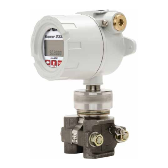
™ Fieldbus Scanner 2000 microEFM for F Section 1 ® oundation Section 1—Introduction The NuFlo™ Scanner 2000 microEFM for F ™ Fieldbus (Figure 1.1, page 8) is a FISCO-certified ® oundation flow computer that communicates via both RTU Modbus and H1 fieldbus protocol. The device computes ®... -
Page 8: Hardware
™ Fieldbus Section 1 Scanner 2000 microEFM for F ® oundation When liquid measurement is the goal and pressure inputs are not required, simply purchase the Scanner 2000 without the MVT and mount it directly to a liquid turbine meter, then install an RTD in the flow line for temperature compensation. - Page 9 ™ Fieldbus Scanner 2000 microEFM for F Section 1 ® oundation Ground screw Conduit plug LCD / keypad LCD / keypad Enclosure lid (remove to access keypad) Mount for pole-mount hardware 3/4 in. to 1 in. adapter Union (connects directly to the turbine meter) Figure 1.2—Scanner 2000 microEFM with turbine meter adapter Lithium battery pack...
-
Page 10: Hardware Options
™ Fieldbus Section 1 Scanner 2000 microEFM for F ® oundation Hardware Options Several hardware options are available for customizing the Scanner 2000 to a user’s specific needs. They include: • communications adapter for enabling a quick connection to a laptop computer •... -
Page 11: Configuration For Fieldbus Communications
™ Fieldbus Scanner 2000 microEFM for F Section 1 ® oundation Event logs track user changes to flow parameters that impact log data. Such changes may include orifice plate changes, K-factor changes, input setting changes, and device events like over-range and resets. Configuration for Fieldbus Communications ™... - Page 12 ™ Fieldbus Section 1 Scanner 2000 microEFM for F ® oundation Table 1.1—Scanner 2000 microEFM Specifications Logging (cont’d) Records up to 16 user-defined parameters Logs stored in non-volatile memory for up to 10 years Memory Non-volatile memory for Modbus configuration and log data 256 KB Modbus Communications/ RS-485 Modbus communications port (300 to 38.4K baud) on main board...
- Page 13 ™ Fieldbus Scanner 2000 microEFM for F Section 1 ® oundation Table 1.1—Scanner 2000 microEFM Specifications Fluid Property Natural Gas: Calculations (cont’d) GPA 2145-09, “Table of Physical Properties for Hydrocarbons and Other Compounds of Interest to the Natural Gas Industry,” Gas Processors Association, Tulsa Oklahoma, 2008.
- Page 14 ™ Fieldbus Section 1 Scanner 2000 microEFM for F ® oundation Table 1.1—Scanner 2000 microEFM Specifications MVT Accuracy (cont’d) Static Pressure Accuracy (300, 500, 1500, and 3000 psia) • ±0.05% of full scale • ±0.25% of full scale over operating temperatures -30°C to 78°C Static Pressure Accuracy (5300 and 5800 psia) •...
- Page 15 ™ Fieldbus Scanner 2000 microEFM for F Section 1 ® oundation Table 1.1—Scanner 2000 microEFM Specifications Modbus Output When configured as alarm output (cont’d): (Main Board, cont’d) • Normally open/normally closed • Safety ratings: Uo = 0, Ui = 30 Vdc, Ii = 60 mA ™ Fieldbus Fieldbus power/communications port on fieldbus interface board (TB4) oundation...
-
Page 16: Flow Rate And Fluid Property Calculations
™ Fieldbus Section 1 Scanner 2000 microEFM for F ® oundation Flow Rate and Fluid Property Calculations The Scanner 2000 calculates flow rates and fluid properties for natural gas, steam and liquid flow. The following descriptions identify the industry standards upon which these calculations are based. Natural Gas The Scanner 2000’s natural gas calculations and data storage conform to AGA-3, AGA-7, AGA-8, API 21.1, and ISO-5167 industry standards. -
Page 17: Compensated Liquid
™ Fieldbus Scanner 2000 microEFM for F Section 1 ® oundation NuFlo Cone Meter (DP Input). The Scanner 2000 supports steam measurement using industry-recognized algorithms identified in the NuFlo Cone Meter User Manual. Fluid properties for steam are calculated in accordance with the IAPWS Industrial-Formulation 1997 (IF-97) standard. Temperature is calculated according to IF-97 for saturated steam, based on static pressure. - Page 18 ™ Fieldbus Section 1 Scanner 2000 microEFM for F ® oundation...
-
Page 19: Section 2-Installing The Scanner 2000
™ Fieldbus Scanner 2000 microEFM for F Section 2 ® oundation Section 2—Installing the Scanner 2000 Overview The Scanner 2000 FISCO-certified field device is safe for use in FISCO intrinsically safe installations when installed in accordance with EN 60079-11:2007, and EN 60079-27:2008. The following customer-supplied equipment is recommended for installation in a fieldbus network: •... -
Page 20: Hazardous Area Installations
™ Fieldbus Section 2 Scanner 2000 microEFM for F ® oundation Hazardous Area Installations The ATEX-certified standard Scanner 2000 microEFM for F ™ Fieldbus is fully compliant with oundation European ATEX Directive 94/9/EC, and has been assessed against the equivalent IEC standards to the following EN standards: EN 60079-0:2006, EN 60079-0:2009, EN 60079-11:2007, and EN 60079-27:2008. -
Page 21: Mounting Options
™ Fieldbus Scanner 2000 microEFM for F Section 2 ® oundation Table 2.1—MVT Pressure Limits, Approvals and Bolt Specifications SP/SWP Max. ASME Standard NACE Bolts (PSIA) (IN H2O) Overrange Pressure Bolts (PSIA) Vessel Code Compliant B7 or 316 SS B7 or 316 SS B7 or 316 SS 1500 2250... - Page 22 ™ Fieldbus Section 2 Scanner 2000 microEFM for F ® oundation The following accessories are also recommended: • a 5-valve manifold for connecting process lines to the integral MVT • an RTD assembly for process temperature input on gas flow runs and compensated liquid flow runs (not recommended for steam flow runs) •...
-
Page 23: Best Practices For Orifice And Cone Meter Installation
™ Fieldbus Scanner 2000 microEFM for F Section 2 ® oundation Measuring Natural Gas via a Differential Pressure Meter Note This section contains installation guidelines for orifice and cone meters. If installing the Scanner 2000 with an averaging pitot tube meter, refer to manufacturer instructions for installation. Best Practices for Orifice and Cone Meter Installation To ensure measurement accuracy, ensure that the meter run complies with the following AGA-3 and ISO 5167 guidelines, as applicable:... -
Page 24: Installation Procedure-Direct Mount To Orifice Meter Or Cone Meter
™ Fieldbus Section 2 Scanner 2000 microEFM for F ® oundation • Install the meter so that the static pressure tap is upstream of the differential pressure tap. The high side of the integral Scanner 2000 sensor must also be situated upstream. •... -
Page 25: Installation Procedure-Remote Mount To Orifice Meter Or Cone Meter
™ Fieldbus Scanner 2000 microEFM for F Section 2 ® oundation 4. Install the RTD assembly in the thermowell. Route the RTD assembly cable through the conduit opening in the top of the Scanner 2000 and connect it to the main circuit board. See Figure 3.6, page 51, for wiring instructions. - Page 26 ™ Fieldbus Section 2 Scanner 2000 microEFM for F ® oundation 3/4” conduit (for Foundation Fieldbus input or communications Manifold adapter) Pressure ports (high/low) RTD assembly Flow Figure 2.5—Remote-mount gas run installation (shown here with a cone meter). The remote-mount method can be used with an orifice meter as well.
-
Page 27: Measuring Natural Gas Via A Turbine Meter
™ Fieldbus Scanner 2000 microEFM for F Section 2 ® oundation Measuring Natural Gas via a Turbine Meter Best Practices The Scanner 2000 microEFM calculates gas flow through a turbine meter in accordance with AGA-7 and API 21.1 industry standards. For optimum performance, ensure that the turbine and Scanner 2000 installation complies with the industry recommendations listed below: •... - Page 28 ™ Fieldbus Section 2 Scanner 2000 microEFM for F ® oundation Fieldbus power input Manifold RTD assembly Flow Static pressure input (manifold equalizer valve must remain open) 10 pipe diameters 5 pipe diameters upstream downstream Figure 2.6—Remote-mount installation in an AGA-7 turbine meter run (shown with terminal housing) 6.
-
Page 29: Measuring Steam Via A Differential Pressure Meter
™ Fieldbus Scanner 2000 microEFM for F Section 2 ® oundation Measuring Steam via a Differential Pressure Meter Note This section contains installation guidelines for orifice and cone meters. If installing the Scanner 2000 with an averaging pitot tube meter, refer to manufacturer instructions for installation. Best Practices The Scanner 2000 microEFM calculates steam flow in accordance with IF-97, AGA-3, and ISO-5167 industry standards. -
Page 30: Installation Procedure-Remote Mount To Orifice Meter Or Cone Meter
™ Fieldbus Section 2 Scanner 2000 microEFM for F ® oundation CAUTION Before starting the system, remove the caps and add water or antifreeze if necessary to completely fill the pots and cold legs. Air trapped in the lines will produce errors in dif- ferential pressure measurements. WARNING: EXPLOSION RISK. Housing temperature must not exceed 70°C (158°F). Excessive temperatures, which could result from ambient conditions combined with radiated and conduc- tive heat from the process, could cause the internal lithium battery to ignite or explode. Installation Procedure—Remote Mount to Orifice Meter or Cone Meter A Scanner 2000 can be mounted remotely and connected to an orifice meter or cone meter with tubing for steam measurement. - Page 31 ™ Fieldbus Scanner 2000 microEFM for F Section 2 ® oundation CAUTION When measuring steam, process connections must be designed to eliminate air pock- ets. This is achieved by making sure all tubing in the cold legs slopes upward. A side- port MVT and block manifold (shown in Figure 2.9) is recommended to help prevent air bubbles from being trapped in the sensor. If a bottom-port MVT is used, the bottom process ports must be plugged or replaced with a drain valve, and side vents must be used for process connections. A block manifold is not recommended for use with bottom port MVTs. Contact a Cameron field representative for assistance. 1. Verify that the meter is properly installed in the flow line (per manufacturer’s instructions). 2. Mount the Scanner 2000 to a 2-in. pipe or to a flat, vertical surface using bolts and the mounting holes in the enclosure.
- Page 32 ™ Fieldbus Section 2 Scanner 2000 microEFM for F ® oundation b. Open the equalizer and bypass/block valves on the block manifold. Make sure the vent valve is closed. c. Remove the corresponding (high pressure or low pressure) vent screw from the side of the MVT and insert a fitting to allow connection of a hand pump or funnel.
-
Page 33: Measuring Liquid Via A Differential Pressure Meter
™ Fieldbus Scanner 2000 microEFM for F Section 2 ® oundation Measuring Liquid via a Differential Pressure Meter Note This section contains installation guidelines for orifice and cone meters. If installing the Scanner 2000 with an averaging pitot tube meter, refer to manufacturer instructions for installation. Best Practices To ensure measurement accuracy, ensure that the meter run complies with the following AGA-3 and ISO 5167 guidelines, as applicable:... -
Page 34: Installation Procedure-Direct Mount To Orifice Meter Or Cone Meter
™ Fieldbus Section 2 Scanner 2000 microEFM for F ® oundation If the Scanner 2000 is mounted to a cone meter, consider the following guidelines in addition to the best practices listed above. • Position the cone meter so that there are zero to five pipe diameters upstream of the meter and zero to three pipe diameters downstream of the meter. -
Page 35: Installation Procedure-Remote Mount To Orifice Meter Or Cone Meter
™ Fieldbus Scanner 2000 microEFM for F Section 2 ® oundation 3. Align the bolt holes in the Scanner 2000 MVT and manifold, and install bolts to mate these components to the football flanges, using o-rings as appropriate. Torque the bolts to the manufacturer’s specification. 4. - Page 36 ™ Fieldbus Section 2 Scanner 2000 microEFM for F ® oundation 3. Install tubing and fittings to connect the high-pressure and low-pressure taps of the DP meter to the pro- cess connections of the block manifold. Install a pair of shut-off valves near the high and low ports of the DP meter.
- Page 37 ™ Fieldbus Scanner 2000 microEFM for F Section 2 ® oundation Important If the process fluid does not present an environmental risk and is stable when depressur- ized, it may be used to bleed air from the lines. If the process fluid can contaminate the environment, or is highly volatile when depressurized as with liquified gases, a different seal fluid should be used to fill the legs. An ideal seal fluid is one that does not dissolve in the process fluid. Bleeding with Process Fluid a. Make sure the shut-off valves in the tubing near the meter pressure taps are closed, and the meter is filled with process fluid. b.
-
Page 38: Measuring Liquid Via A Turbine Meter
™ Fieldbus Section 2 Scanner 2000 microEFM for F ® oundation Measuring Liquid via a Turbine Meter Best Practices The Scanner 2000 microEFM calculates uncompensated liquid flow through a turbine meter in accordance with API MPMS, Chapter 5, Section 3, Measurement of Liquid Hydrocarbons by Turbine Meters. The Scanner 2000 microEFM calculates compensated liquid flow through a turbine meter in accordance with API- 2540 and the measurement principles upon which the AGA-7 standard is based. -
Page 39: Performing A Manifold Leak Test
™ Fieldbus Scanner 2000 microEFM for F Section 2 ® oundation 3. Screw the Scanner 2000 onto the flowmeter threads surrounding the magnetic pickup with the display fac- ing the desired direction. 4. Tighten all sections of the pipe union. 5. -
Page 40: Static Pressure Calibration And Verification
™ Fieldbus Section 2 Scanner 2000 microEFM for F ® oundation Static Pressure Calibration and Verification Note The pressure range stamped on the MVT is expressed as psia (absolute). However, Scanner 2000 pressure inputs are recalibrated as psig (gauge) at the factory before the device is shipped. There- fore, pressure readings displayed on the LCD and in the ModWorX Pro software are in terms of psig. -
Page 41: Differential Pressure Calibration And Verification
™ Fieldbus Scanner 2000 microEFM for F Section 2 ® oundation Differential Pressure Calibration and Verification The static pressure and differential pressure inputs are calibrated and verified before the Scanner 2000 leaves the factory, and recalibration in the field may or may not be required. To comply with API standards for verification, “as found”... -
Page 42: Placing The Scanner Into Operation
™ Fieldbus Section 2 Scanner 2000 microEFM for F ® oundation Placing the Scanner into Operation To put the Scanner into operation: 1. Close the vent valve. 2. Open the equalizer valves. EQUALIZER EQUALIZER 3. Open the bypass/block valves to allow pressure to be supplied to both sides of the MVT. -
Page 43: Industry Standards For Cone Meters
™ Fieldbus Scanner 2000 microEFM for F Section 2 ® oundation Table 2.2—Industry Standards for Orifice Meters Standard Applicable Section Description Notes AGA Report No. 3: Part 2: Specification Specifications for orifice This standard is also distributed Orifice Metering of and Installation meters (to include beta under the following names: API Natural Gas and Other... - Page 44 ™ Fieldbus Section 2 Scanner 2000 microEFM for F ® oundation Table 2.3—Industry Standards for Turbine Meters Standard Applicable Section Description Notes AGA Report No. 7: Section 7- Installation of gas turbine This specification Measurement of Installation meters to include flow applies to axial-flow Natural Gas by Turbine Specifications...
-
Page 45: Section 3-Wiring The Scanner 2000
™ Fieldbus Scanner 2000 microEFM for F Section 3 ® oundation Section 3—Wiring the Scanner 2000 Field Wiring Connections CAUTION See ANSI/ISA RP12.06.01-2003, Recommended Practice for Wiring Methods for Hazard- ous (Classified) Locations Instrumentation for wiring instructions. Local wiring ordinanc- es may also apply. Terminal block screws must be tightened to a minimum torque of 5 to 7 in-lbs. to secure the wiring within the terminal block. Only personnel who are experi- enced with field wiring should perform these procedures. The Scanner 2000 is bus-powered by a two-conductor fieldbus cable that provides both power and communications. A Scanner may be added to the network or removed from the network while the bus is running. -
Page 46: Basic Wiring
™ Fieldbus Section 3 Scanner 2000 microEFM for F ® oundation Basic Wiring A standard Scanner 2000 with MVT has two conduit openings in the top of its housing for field wiring. The following procedure describes the steps for wiring a standard Scanner 2000 for operation using the fieldbus power supply and one additional input or output. -
Page 47: Grounding Procedures
™ Fieldbus Scanner 2000 microEFM for F Section 3 ® oundation 9. If external and internal power supplies were removed, reset the clock to ensure that the time stamps in the log data are accurate. The clock can be reset using the instrument keypad or ModWorX™ Pro software. 10. -
Page 48: Power Supply Wiring
™ Fieldbus Section 3 Scanner 2000 microEFM for F ® oundation Power Supply Wiring Lithium Battery Pack The Scanner 2000 microEFM is shipped with a lithium battery pack. In F ™ fieldbus applications, oundation this battery pack provides backup power. Primary power is provided by a fieldbus power supply. To supply backup power to the instrument, connect the lithium battery cable to connector J1 on the main circuit assembly (Figure 3.3). -
Page 49: F Oundation ™ Fieldbus Power Supply
™ Fieldbus Scanner 2000 microEFM for F Section 3 ® oundation ™ Fieldbus Power Supply oundation The Scanner 2000 is bus-powered by a F ™ fieldbus power supply. A two-conductor cable connects oundation the power supply to the fieldbus interface board inside the Scanner 2000 enclosure. Route the cable through the conduit opening in the top of the enclosure and wire as shown in Figure 3.4. -
Page 50: Input Wiring
™ Fieldbus Section 3 Scanner 2000 microEFM for F ® oundation Input Wiring Turbine Flowmeter Input The Turbine Input on the main circuit board provides the turbine flowmeter input signal generated by a magnetic pickup, enabling the Scanner 2000 to calculate and display instantaneous flow rates and accumulated totals. -
Page 51: Rtd Input
™ Fieldbus Scanner 2000 microEFM for F Section 3 ® oundation RTD Input The RTD is installed in a thermowell downstream of the primary differential pressure source. The location of the thermowell should conform to the relative standard to ensure accurate measurement. A 4-wire, 100-ohm platinum RTD is recommended for performing orifice gas, compensated liquid, or gas turbine calculations, though a 2- or 3-wire RTD may prove functional. -
Page 52: Output Wiring
™ Fieldbus Section 3 Scanner 2000 microEFM for F ® oundation Output Wiring Digital Output (Pulse or Alarm) The standard Scanner 2000 supports a solid-state digital output that is configurable as either a pulse output or an alarm output. As a pulse output, the pulse width duration and pulse representation are both configurable. Because the circuit is isolated, it can be used in conjunction with any other feature on the Scanner 2000. -
Page 53: Rs-485 Output-Computer Connection
™ Fieldbus Scanner 2000 microEFM for F Section 3 ® oundation RS-485 Output—Computer Connection The RS-485 output is required for communication with the ModWorX Pro interface software. An RS-232 to RS-485 converter cable (Part No. 9A-101283116) is required for connecting the Scanner 2000 to an RS-232 PC port. - Page 54 ™ Fieldbus Section 3 Scanner 2000 microEFM for F ® oundation...
-
Page 55: Section 4-Scanner 2000 Configuration And Operation
™ Fieldbus Scanner 2000 microEFM for F Section 4 ® oundation Section 4—Scanner 2000 Configuration and Operation Note This section discusses the configuration of device inputs and outputs using Modbus communications. Fieldbus communications are configured separately using a configuration tool. See Section 5—Field- bus Configuration and Operation for details. - Page 56 ™ Fieldbus Section 4 Scanner 2000 microEFM for F ® oundation CONFIGURATION: CONFIGURATION: Move between menus Save configuration and menu selections settings OPERATION: OPERATION: View next parameter Save totals CONFIGURATION: Change digits and other menu selections PRESS PRESS OPERATION: View daily logs simultaneously to view simultaneously to access time/date, temperature,...
-
Page 57: Entering The Slave Address
™ Fieldbus Scanner 2000 microEFM for F Section 4 ® oundation Entering the Slave Address The slave address is a setting used in Modbus communications. It is a number that ranges from 1 to 65535, ® excluding 252 to 255 and 64764, which are reserved. If the Modbus request message contains the matching ®... -
Page 58: Editing The Date And Time
™ Fieldbus Section 4 Scanner 2000 microEFM for F ® oundation Editing the Date and Time A user can change the date and time from the keypad. To Edit the Date and Time: Enter the Access menu. Press UP ARROW and ENTER simultaneously. -
Page 59: Editing The Contract Hour
™ Fieldbus Scanner 2000 microEFM for F Section 4 ® oundation Editing the Contract Hour A user can set the contract hour from the keypad. The contract hour determines the exact time the daily flow is logged, and is represented by a four-digit number displayed in military time. To Edit the Contract Hour: Enter the Access menu. -
Page 60: Editing The Plate Size
™ Fieldbus Section 4 Scanner 2000 microEFM for F ® oundation Editing the Plate Size When the differential pressure producer in a Scanner 2000 installation is an orifice meter and security controls allow, a user can change the size of the orifice plate from the keypad. The plate size is displayed in inches. If “Strict API compliance”... -
Page 61: Viewing Daily And Hourly Logs
™ Fieldbus Scanner 2000 microEFM for F Section 4 ® oundation Viewing Daily and Hourly Logs Pressing the Log button (Figure 4.1, page 56) changes the LCD display mode from normal operation (scrolling) to a daily log view mode. The two-digit flashing number or “log index” on the left side of the LCD represents the number of days that have passed since the log was saved. - Page 62 ™ Fieldbus Section 4 Scanner 2000 microEFM for F ® oundation...
-
Page 63: Section 5-Fieldbus Configuration And Operation
™ Fieldbus Scanner 2000 microEFM for F Section 5 ® oundation Section 5—Fieldbus Configuration and Operation Overview At the core of the Scanner 2000 is an electronics package that measures and computes standard volumes of gas, steam, petroleum liquids, and generic liquids with a high degree of accuracy and with very low power consumption. -
Page 64: Resource Block
™ Fieldbus Section 5 Scanner 2000 microEFM for F ® oundation • The Permitted setting determines the mode options that may be selected as the Target mode. • The Normal setting is a reminder of the normal operating mode that the block should be returned to in the event that the mode is changed, either by a user or as the result of operating conditions. -
Page 65: Device Identification
™ Fieldbus Scanner 2000 microEFM for F Section 5 ® oundation At a minimum, the user must enter the following parameter settings when configuring an AI block: • mode parameter (target) • assignment of AI block to a channel (defines the process variable measurement that will be used as input to the AI block) •... -
Page 66: Configuring Fieldbus Communications
™ Fieldbus Section 5 Scanner 2000 microEFM for F ® oundation IMPORTANT If multiple devices with the same default node address are being installed and the configura- tion tool uses the node address to identify a device, the host or configuration tool may not detect all devices at the first attempt. - Page 67 ™ Fieldbus Scanner 2000 microEFM for F Section 5 ® oundation 3. Verify that the engineering units displayed by the XD-SCALE>UNITS_INDEX parameter match the units displayed in the transducer block (as configured in ModWorX Pro and read from Modbus registers). If the units displayed in the transducer block and the AI block differ, change the AI block units.
-
Page 68: Control Loop Design
™ Fieldbus Section 5 Scanner 2000 microEFM for F ® oundation e. Set a priority level for each alarm, as appropriate, by selecting a numeric code from the five priority levels supported: 0 = alarm not used 1 = alarm is recognized by the network, but is not reported to the user 2 = alarm is reported to the user 3-7 = advisory alarms of increasing priority, with 7 being the highest priority 8-15 = critical alarms of increasing priority with 15 being the highest priority... -
Page 69: Fieldbus Troubleshooting
™ Fieldbus Scanner 2000 microEFM for F Section 5 ® oundation Status can indicate a hardware, communication, or other fault. Each status is made up of three forms of intelligence: quality, sub-quality, and limit condition. • Quality indicates status in general terms: good, uncertain, or bad. •... -
Page 70: Communication Faults
™ Fieldbus Section 5 Scanner 2000 microEFM for F ® oundation Communication Faults When a communication fault occurs, use the configuration tool to determine if it affects a single device or the entire network. If a device fails to communicate, it will be removed from the live list displayed in the configuration tool. -
Page 71: Section 6-Scanner 2000 Maintenance
™ Fieldbus Scanner 2000 microEFM for F Section 6 ® oundation Section 6—Scanner 2000 Maintenance The ATEX-certified Scanner 2000 for F ™ Fieldbus is fully compliant with European ATEX oundation Directive 94/9/EC. User repairs are to be limited to the battery and component replacement procedures described in this manual. - Page 72 ™ Fieldbus Section 6 Scanner 2000 microEFM for F ® oundation To replace a lithium battery pack, perform the following steps: 1. Unscrew the cover from the enclosure and set it aside. 2. Using a small standard blade screwdriver, remove the two #4-40 × 7/8” screws located to the right and left side of the display (Figure 6.1).
-
Page 73: Board Replacement
™ Fieldbus Scanner 2000 microEFM for F Section 6 ® oundation Board Replacement The Scanner 2000 electronic circuitry includes three boards (Figure 6.2). The main board (on bottom of the board stack when the assembly is removed from the enclosure) is attached to a smaller fieldbus interface board, which is in turn attached to a white potted fieldbus module. - Page 74 ™ Fieldbus Section 6 Scanner 2000 microEFM for F ® oundation 3. Lift the board assembly from the enclosure, taking precautions to avoid straining the sensor ribbon cable connection. 4. Record the locations of all cable connections to the main board. 5.
- Page 75 ™ Fieldbus Scanner 2000 microEFM for F Section 6 ® oundation 10. Disconnect the sensor ribbon cable from the J5 connector on the main board as follows: a. Lift the latch from the black clip securing the ribbon cable (Figure 6.6). b.
- Page 76 ™ Fieldbus Section 6 Scanner 2000 microEFM for F ® oundation 11. Remove the main board/keypad assembly from the enclosure. 12. Remove the two #4-40 × 5/16” screws fastening the main board to the keypad (Figure 6.7, page 76). 13. Remove the keypad ribbon cable from the J7 connector on the LCD side of the main board by pressing in on the sides of the black plastic clip and pulling gently on the clip.
-
Page 77: Fieldbus Interface Board
™ Fieldbus Scanner 2000 microEFM for F Section 6 ® oundation 16. Connect the main board to the keypad with the two #4-40 × 5/16” screws removed in step 12. 17. Reconnect the sensor ribbon cable to the J5 connector at the top of the main board, by inserting the ribbon cable into the black clip and securing the latch on the clip to hold it tightly in place. -
Page 78: Fieldbus Module
™ Fieldbus Section 6 Scanner 2000 microEFM for F ® oundation 7. Reattach the board assembly to the standoffs inside the enclosure with the two #4-40 × 7/8” screws re- moved in step 2 of the main board replacement procedure. 8. -
Page 79: Mvt Replacement
™ Fieldbus Scanner 2000 microEFM for F Section 6 ® oundation 6. Reconnect the white potted fieldbus module to the fieldbus interface board, being careful to align the pins on the back side of the module with the header on the interface board, and secure it with the two screws removed in step 8 of the main board replacement procedure. - Page 80 ™ Fieldbus Section 6 Scanner 2000 microEFM for F ® oundation 12. Reconnect all wiring to terminal blocks TB1, TB2 and TB3. 13. Reconnect the battery cable to connector J1 on the main board. 14. Reconnect the fieldbus input cable to terminal block TB4 on the fieldbus interface board. 15.
-
Page 81: Section 7-Spare Parts
Scanner 2000 microEFM Section 7 ® Section 7—Spare Parts WARNING: Substitution of components may impair suitability for ATEX certification. Use of spare parts other than those identified by Cameron International Corporation voids hazardous area certification. Cameron bears no legal responsibility for the performance of a product that has been serviced or repaired with parts that are not authorized by Cameron. Table 7.1—Scanner 2000 microEFM Spare Parts Part Number Description 9A-30160010 Circuit Assembly, Scanner 2000 EFM, CPU Board 2296336-01 Fieldbus Module, Scanner 2000 EFM 2296330-01 Circuit Assembly, Scanner 2000 EFM, Fieldbus Interface Board 9A-30166005 Assembly, Switchplate, Scanner 2000 EFM 9A-100002605... - Page 82 Section 7 Scanner 2000 microEFM ® Table 7.2—Scanner 2000 microEFM Optional Parts Part Number Description 9A-90017004 Adapter, Communications, 3/4 in. NPT Union, 2-Pin Connector, 10 in., for External RS-485 Communications 9A-0112-9015T RS-232 to RS-485 Converter, Serial Port Powered, DB9 Connector on Both Ends 9A-101283116 RS-232 to RS-485 Converter, Serial Port Powered, DB9 Connector on PC End, Open Terminals on Instrument End...
-
Page 83: Appendix A-Scanner 2000 Hardware Options
™ Fieldbus Scanner 2000 microEFM for F Appendix A ® oundation Appendix A—Scanner 2000 Hardware Options External Communications Adapter (9A-90017004) The external communications adapter (Figure A.1) provides an RS-485 connection for connecting a laptop or PC to the instrument without removing the instrument cover. When the adapter is ordered with a Scanner 2000, it is factory installed. - Page 84 ™ Fieldbus Appendix A Scanner 2000 microEFM for F ® oundation 3.95 (100.4) 6.81 (172.9) Figure A.2—Dimensions of external communications adapter; inches (mm) To connect a PC or laptop to the communications adapter, perform the following steps: 1. Unscrew the union nut to expose the connector socket shown in Figure A.1, page A-1.
-
Page 85: Communications Adapter Installation (For Adapters Purchased Separately From A Scanner 2000
™ Fieldbus Scanner 2000 microEFM for F Appendix A ® oundation To disconnect the adapter, remove the plug connector (with converter cable attached) from the socket, place the blanking plug inside the union nut (removed in step 1) and screw the union nut onto the union half to cover the socket. -
Page 86: Terminal Housing (Part No. 2296352-01
™ Fieldbus Appendix A Scanner 2000 microEFM for F ® oundation Pole mount kit Pole mount kit MVT adapter Figure A.4 —Scanner 2000 with MVT, remote-mounted on a 2-in. pole using a NuFlo hardware kit (Part No. 9A-30028004) Important The vertical pipe mount configuration shown in Figure A.4 is not recommended for side- port MVTs when mated with a block manifold for liquid or steam measurement. A hori- zontal pipe mount should be considered for these installations. - Page 87 ™ Fieldbus Scanner 2000 microEFM for F Appendix A ® oundation PLUGGED PORT JUNCTION CABLE GLAND (POWER INPUT) PORT (RS-485) SHOWN WITH COVER REMOVED CABLE GLAND (RTD) 4-WIRE 10’ ARMOURED RTD CABLE ASSY. Figure A.5—Terminal housing installation dimensions TO SCANNER 2000 FROM FIELDBUS FIELDBUS INTERFACE BOARD POWER SUPPLY...
- Page 88 ™ Fieldbus Appendix A Scanner 2000 microEFM for F ® oundation TO SCANNER 2000 MAIN BOARD, TB1, TERMINALS 1-4 (FACTORY-WIRED) JUNCTION BOX (OPTIONAL) FROM RTD (4-WIRE RECOMMENDED) Figure A.7— F ™ fieldbus process temperature input wiring with terminal housing oundation...
-
Page 89: Appendix B-Lithium Battery Information
™ Fieldbus Scanner 2000 microEFM for F Appendix B ® oundation Appendix B—Lithium Battery Information Transportation Information WARNING: The Scanner 2000 microEFM contains lithium batteries. The internal component (thionyl chloride) is hazardous under the criteria of the Federal OHSA Hazard Communication Standard 29 CFR 1920.1200. Before shipping a lithium battery or equipment containing a lithium battery, verify that the packaging and labeling conforms with the latest version of all applicable regulations. The transport of the lithium batteries is regulated by the United Nations, “Model Regulations on Transport of Dangerous Goods,” (special provisions 188, 230, and 310), latest revision. Within the US the lithium batteries and cells are subject to shipping requirements under Part 49 of the Code of Federal Regulations (49 CFR, Parts 171, 172, 173, and 175) of the US Hazardous Materials Regulations (HMR), latest revision. -
Page 90: Material Safety Data Sheet
™ Fieldbus Appendix B Scanner 2000 microEFM for F ® oundation Material Safety Data Sheet For a link to the current MSDS for the lithium batteries used to power the Scanner 2000 microEFM, see the Measurement Systems Division section of the Cameron website: www.c-a-m.com. -
Page 91: Appendix C-Fieldbus Communications Protocol
™ Fieldbus Scanner 2000 microEFM for F Appendix C ® oundation Appendix C—Fieldbus Communications Protocol Device Properties The following data may be useful in identifying the Scanner 2000 device and device description in a host network: • Manufacturer’s ID: 0x43414D • Device Type: 01 •... - Page 92 ™ Fieldbus Appendix C Scanner 2000 microEFM for F ® oundation Table C.1—Resource Block Parameters Index Parameter Definition DD_REV Revision of the device description associated with the resource GRANT_DENY Option for controlling access of host computer and local panel to operating, tuning and alarm parameters of the block HARD_TYPES The types of hardware available as channel numbers...
- Page 93 ™ Fieldbus Scanner 2000 microEFM for F Appendix C ® oundation Table C.1—Resource Block Parameters Index Parameter Definition UPDATE_EVT Alert generated by any change to the static data BLOCK_ALM Alarm used for all configuration, hardware, connection failure or system problems in the block. The cause of the alert is entered in the subcode field.
- Page 94 ™ Fieldbus Appendix C Scanner 2000 microEFM for F ® oundation Table C.2—Transducer Block Parameters Relative Parameter Definition 2018 TV_UNIT Enumerated unit for Tertiary value 2019 QV_VALUE Value of Quaternary value parameter and its status 2020 QV_UNIT Enumerated unit for Quaternary value 2021 SIMULATION_VALUE Value of Simulation value parameter and its status...
- Page 95 ™ Fieldbus Scanner 2000 microEFM for F Appendix C ® oundation Table C.2—Transducer Block Parameters Relative Parameter Definition 2043 GENERIC_USIGN32_ Real Time On SC2000 (YYMM) PARAM_2 2044 GENERIC_USIGN32_ Real Time On SC2000 (DDhh) PARAM_3 2045 GENERIC_USIGN32_ Real Time On SC2000 (mmss) PARAM_4 2046 GENERIC_USIGN32_...
- Page 96 ™ Fieldbus Appendix C Scanner 2000 microEFM for F ® oundation Table C.3—Analog Input Block Parameters Index Parameter Definition IO_OPTS Options for altering input and output block processing. STATUS_OPTS Options which the user may select in the block processing of status.
-
Page 97: Control Registers
™ Fieldbus Scanner 2000 microEFM for F Appendix C ® oundation Table C.4—Transducer Error (XD_Error) and Block Alarm Codes Value Error Description Unspecified error Indicates occurrence of unidentified error General error Error cannot be classified as one of the following errors Calibration error Error occurred during calibration of the device or calibration error detected during device operation... -
Page 98: Unit Conversion
™ Fieldbus Appendix C Scanner 2000 microEFM for F ® oundation Unit Conversion The following table can be used to convert numeric code to units, which may be helpful in working with host systems that do not convert unit codes to text descriptions automatically. Table C.6—Unit Conversions for XD Scale Unit Display... - Page 99 ™ Fieldbus Scanner 2000 microEFM for F Appendix C ® oundation Unit Display Unit Unit Display Unit Code (Fieldbus) Code (Fieldbus) 1348 m3/min cubic meter per minute 1330 lb/s pound per second 1349 m3/h cubic meter per hour 1331 lb/min pound per minute 1350 m3/d...
- Page 100 ™ Fieldbus Appendix C Scanner 2000 microEFM for F ® oundation C-10...
- Page 101 WARRANTY - LIMITATION OF LIABILITY: Seller warrants only title to the products, software, supplies and materials and that, except as to software, the same are free from defects in workmanship and materials for a period of one (1) year from the date of delivery. Seller does not warranty that software is free from error or that software will run in an uninterrupted fashion.
Need help?
Do you have a question about the NuFlo Scanner 2000 and is the answer not in the manual?
Questions and answers