
Related Manuals for Sensia NUFLO MC-I


Summary of Contents for Sensia NUFLO MC-I
- Page 1 NUFLO MC-I Portable Rate Meter User Manual Exia INTRINSICALLY SAFE FOR HAZARDOUS LOCATIONS CLASS I, DIV. 1, GROUPS A,B,C,D 167018 Manual No. 9A-50165007, Rev. 01...
- Page 2 Manual No. 9A-50165007, Rev. 01 December 2012...
-
Page 3: Table Of Contents
Table of Contents Introduction ............................1 Specifications ............................4 Operating the MC-I Portable Rate Meter .................... 5 Table 1—MC-I Keypad Functions ...................... 5 RUN Mode Keypad Functions ......................6 Calibrating for Liquid Measurement Using Standard Units ............. 7 Calibrating for Liquid Measurement Using a Calculated Divisor ..........10 Example Calibration: Liquid Measurement Using a Calculated Divisor ........... - Page 4 December 2012...
-
Page 5: Introduction
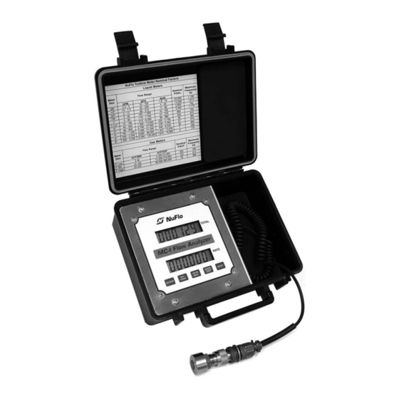
Introduction NuFlo’s MC-I Portable Rate Meter is a portable, easy-to-use readout instrument that accurately displays accumulated flow volume and flow rate of liquids and gases using alkaline battery power. The MC-I Portable Rate Meter’s microprocessor circuitry counts the pulses generated by a flow meter, converts that data into volume and rate values in accordance with calibration settings, and displays the totalized data on two six-digit liquid crystal displays (LCDs). - Page 6 Figure 1—Nomenclature (exterior) December 2012...
- Page 7 Figure 2—Nomenclature (interior) December 2012...
-
Page 8: Specifications
Specifications Enclosure: Black ABS plastic, weatherproof design Size: 8.78 in. wide x 3 7/16 in. high x 7 7/8 in. deep (including hinge and handle) Weight: 3.2 lb (including batteries) Shipping weight: 5 lb (including shipping container) Power supply: Alkaline battery pack (3 “C” batteries) supplied with instrument Temperature range: 0 to +130°F (-18 to +55°C) Totalizer:... -
Page 9: Operating The Mc-I Portable Rate Meter
Operating the MC-I Portable Rate Meter When fluid begins to pass through the flow meter, the MC-I Portable Rate Meter registers total accumulated flow volume in the top LCD and instantaneous flow rate in the bottom LCD. Decimal points will appear in their proper position in the displays when the unit is properly calibrated. The MC-I Portable Rate Meter has two modes of operation: Run Mode and Calibrate Mode. -
Page 10: Run Mode Keypad Functions
RUN Mode Keypad Functions Saving/Storing Data Loss of battery power can result in the loss of unsaved data. To store the total accumulated flow volume to nonvolatile memory, press ENTER/STEP each time you check the flow. The saved total accumulated volume value will be available when battery power is restored. Total accumulated volumes are also automatically saved each time you exit the Calibrate menu. -
Page 11: Calibrating For Liquid Measurement Using Standard Units
Calibrating for Liquid Measurement Using Standard Units The following information is needed to calibrate the MC-I Portable Rate Meter when measuring liquids: • unit of measure for volume • flow meter calibration factor (in pulses per gallon) • unit of measure for flow rate The calibration procedure is explained in detail below. - Page 12 5. Press ENTER/STEP to accept the selection. The SAVing screen will appear momentarily, and the MC-I Portable Rate Meter will then automatically return to Run mode. The total volume and rate information will be displayed in the top and bottom displays, respectively. Important: If the unit of measure selected for the flow rate results in a volume that contains too many digits to be displayed in the LCD window, the MC-I Portable Rate Meter will generate an overrun error.
- Page 13 3. When Pu.P.gAL appears in the upper display, enter the flow meter calibration factor in pulses per gallon according to the steps below. The lower display will show the previously entered flow meter calibration factor. The factory default is 900.00. The right-most digit—the hundredths position—will blink, indicating it is the digit currently selected for editing.
-
Page 14: Calibrating For Liquid Measurement Using A Calculated Divisor
Calibrating for Liquid Measurement Using a Calculated Divisor Calculating the divisor for liquids is necessary when registering the volume in units other than barrels, gallons, cubic meters, or liters. Important: Since user-defined units are not available on the MC-I Portable Rate Meter, the GAL totals engineering unit must be used. -
Page 15: Example Calibration: Liquid Measurement Using A Calculated Divisor
4. At the rAt.Eng prompt, press INCREMENT repeatedly until the appropriate unit of measure appears in the bottom display. Unit options include: • barrels per day (b.P.d) • gallons per minute (g.P.nn) • cubic meters per day (nn3.P.d) • liters per minute (Lit.P.nn) •... - Page 16 1. Press the ACCESS key to enter the Calibrate mode and wait for the MC-I Portable Rate Meter to complete a diagnostic test. 2. When the prompt tot.Eng appears in the upper display, press INCREMENT to scroll through the available volume units of measurement (bbl, gal, m³, liter). Select “gal” from the unit menu. Press ENTER/STEP to accept the selection.
-
Page 17: Calibrating For Gas Measurement Using A Calculated Divisor
Calibrating for Gas Measurement Using a Calculated Divisor To perform gas flow measurement with the MC-I Portable Rate Meter, the divisor must be calculated. Since gas units are not available on the MC-I Portable Rate Meter, the GAL totals engineering unit must be used. - Page 18 2. Press INCREMENT repeatedly to select gAL for the unit of measure for volume (bottom , and liter. Press ENTER/STEP to accept the selection. The display). Unit options are bbl, gal, m Pu.P.gAL menu will appear in the top display. 3.
-
Page 19: Example Calibration: Gas Measurement Using A Calculated Divisor
Example Calibration: Gas Measurement Using a Calculated Divisor A NuFlo 2-in. high-range gas turbine flow meter will be measuring gas flow with an average flowing pressure of 120 PSIG and an average flowing temperature of 50 degrees Fahrenheit (°F). The flow meter factor is 72.56 pulses per actual cubic foot (PACF). - Page 20 a. Press DEC-POINT till the decimal point is in the thousands position. b. Since 6 is the rightmost digit to be entered (in the thousandths position for the factor 270.246), press INCREMENT until 8 is displayed. c. Since 4 is the next digit to be entered (in the hundredths position for the factor 270.246), press INCREMENT until 4 is displayed.
- Page 21 Table 2—Determining Atmospheric Pressure from Elevation Elevation Atmospheric Pressure (Feet Above Sea Level) (Pounds per Square Inch) 14.73 14.47 1000 14.21 1500 13.95 2000 13.70 2500 13.45 3000 13.21 3500 12.97 4000 12.74 4500 12.51 5000 12.28 5500 12.06 6000 11.84 6500 11.63...
- Page 22 Table 4—Liquid Volume Conversions Gallons per Barrel = 42 Gallons per Cubic Meter = 264.17 Gallons per Liter = 0.26417 Gallons per Kiloliter = 264.17 Gallons per Pound = 1 / (SG x 8.337) This table is based on the US liquid gallon and 42-gallon (API) barrel. Specific gravity (SG) is based on the specific gravity of water (1).
-
Page 23: Maintenance
Maintenance Battery Replacement See Table 7, page 22, for recommended spare parts. WARNING SUBSTITUTION OF SPARE PARTS OTHER THAN THOSE IDENTIFIED BY CAMERON MAY IMPAIR INTRINSIC SAFETY AND VOIDS CSA CERTIFICATION. CAMERON BEARS NO LEGAL RESPONSIBILITY FOR THE PERFORMANCE OF A PRODUCT THAT HAS BEEN SERVICED OR REPAIRED WITH PARTS THAT ARE NOT AUTHORIZED BY CAMERON. - Page 24 Figure 3—Alkaline battery pack replacement December 2012...
-
Page 25: Circuit Assembly Replacement
Circuit Assembly Replacement The circuit assembly contains all of the electronic components. To replace the circuit card, perform the following steps: 1. Open the two latches on the enclosure and open the lid. 3. Loosen the four large Philips screws on the top and bottom edge of the front panel and remove the front panel. -
Page 26: Switchplate Assembly Replacement
9. Place the new circuit assembly over the 4-40 studs in the same position as the old circuit assembly that was removed. 10. Replace the four nuts removed in step 8. 11 Replace the battery mounting bracket removed in step 5. 12. -
Page 27: Spare Parts
Spare Parts WARNING SUBSTITUTION OF SPARE PARTS OTHER THAN THOSE IDENTIFIED BY CAMERON MAY IMPAIR INTRINSIC SAFETY AND VOIDS CSA CERTIFICATION. CAMERON BEARS NO LEGAL RESPONSIBILITY FOR THE PERFORMANCE OF A PRODUCT THAT HAS BEEN SERVICED OR REPAIRED WITH PARTS THAT ARE NOT AUTHORIZED BY CAMERON. - Page 31 WARRANTY - LIMITATION OF LIABILITY: Seller warrants only title to the products, software, supplies and materials and that, except as to software, the same are free from defects in workmanship and materials for a period of one (1) year from the date of delivery.
Need help?
Do you have a question about the NUFLO MC-I and is the answer not in the manual?
Questions and answers