Table of Contents
Advertisement
Quick Links
CONTENTS
Section 1 - Introduction ............................................................. Page 1
Specifications ..................................................................... Page 2
Section 2 - Installation/Operation ............................................... Page 3
Section 3 - Maintenance/Calibration/Rapair ................................ Page 5
Calibration ......................................................................... Page 6
Repair ............................................................................... Page 9
Conversion to M380 ........................................................... Page 11
Section 4 - Install/Dimensional Drawings..................................... Page 12
M306 ................................................................................ Page 14
M380 ................................................................................ Page 17
SECTION 1 - INTRODUCTION
General
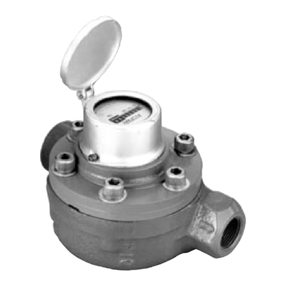
The Barton Model 306 Flotrac uses a "constrained vortex" principle to meter
high pressure, non-viscous liquids accurately and efficiently over a broad range.
The water or liquid being metered may contain some abrasive and corrosive
materials destructive to other types of meters. The rotor, shaft, and register
gearing are the only moving parts in the Flotrac meter.
The housing is epoxy-coated cast steel. The rotor and housing inserts are Ryton
R4, practically impervious to dissolved salts and alkalies, water and most acids.
A magnetic coupling rotor to register eliminates packing and leakage and has a
fail-safe device to prevent register "blow up" in high pressure service. The rotor
bearings and journals are of special materials providing exceptional service life
with water or non-lubricating liquids.
Before installing this instrument, become familiar with the installation instructions in
Section 2. WARNING notes that appear on the following pages of this manual should
be reviewed before proceeding: 5 and 11.
WARNING notes indicate the presence of a hazard which can cause severe personal
injury, death, or substantial property damage if warning is ignored.
Barton
Installation Manual
SAFETY
MODEL 306
®
Flotrac
Meter
®
Version 01E10c
ID#10360
5/2001
Advertisement
Table of Contents

Related Manuals for Sensia Barton 306


Summary of Contents for Sensia Barton 306
-
Page 1: Table Of Contents
MODEL 306 Barton ® Flotrac Meter ® Installation Manual Version 01E10c ID#10360 5/2001 CONTENTS Section 1 - Introduction ............. Page 1 Specifications ..............Page 2 Section 2 - Installation/Operation ..........Page 3 Section 3 - Maintenance/Calibration/Rapair ........ Page 5 Calibration ................. Page 6 Repair ................ -
Page 2: Specifications
In-line examination of all parts exposed to the process liquid is simple. First depressurize the meter. Then by unscrewing six cap screws and removing the meter cover, the rotor can be slipped off for inspection or replacement. Specifications M306 Cross-section View... -
Page 3: Section 2 - Installation/Operation
SECTION 2 - INSTALLATION/OPERATION General The instrument should be inspected at time of unpacking to detect any damage that may have occurred during shipment. Pre-check The Model 306 Flotrac Meter was calibrated at the factory on clean water befor e shipment. If further calibration is r equir ed, contact the near est Cameron r epr esentative . - Page 4 Both liquid streams rejoin at the meter outlet which is in direct line with the meter inlet. Startup Procedure A. Practical Considerations The following practices should be observed when installing and starting a Flotrac meter. See cross-sectional illustration above and by-pass location drawing at the top of the next page.
-
Page 5: Section 3 - Maintenance/Calibration/Rapair
SECTION 3 - MAINTENANCE/CALIBRATION WARNING A METER IN LINE SHOULD BE DISASSEMBLED ONLY AFTER PRESSURE IS REMOVED FROM THE LINE. Periodic Maintenance Regular inspection and preventive maintenance should insure extended trouble- free operation. The following procedure is suggested as a basis for a mainte- nance program. -
Page 6: Calibration
Troubleshooting If trouble develops, the procedures listed in Table below will usually locate the problem and suggest a solution. Normally, problems will be restricted to the rotor assembly, magnetic drive coupling or register assembly. Calibration The Model 306 Flotrac Meter was calibrated at the factory using clean water. If subsequent proving shows a change in the calibration constant, the meter can be corrected by changing the calibration gears. - Page 7 Using "US Barrels" Table below, move along the vertical axis (at P/I combina- tion) to 18/75. As shown, selection of a new pinion input gear combination with a 17-tooth pinion gear and a 74-tooth input gear will result in a -4.28 correction.
-
Page 9: Repair
Gear Part Numbers Repair Repairs are readily made on the meter, either in-line or on the bench. Remem- ber that all threads are right-handed, and that parts should be installed in reverse order of removal. In addition, 0-rings should be inspected prior to reassembly, and replaced if cuts or swelling are evident. - Page 10 B. Journal Tube Replacement (continued) To install the tube assembly - Align the rotor with the tube, insert the tube into the cover with care not to pinch the O-ring as it slides into place, and tighten the tube with the wrench. NOTE: The cover register cavity must be dry at all times.
-
Page 11: Conversion To M380
Conversion to Model 380 The Model 306 Flotrac Meter (capacity 9-90 gpm) can be converted to a Model 380 Flow Meter (capacity 1.5-15 gpm) by replacing the parts noted in the Table below. When making this conversion, refer to M306 and M380 Parts Drawings and Parts Lists in Section 5 (starting on page 14). -
Page 12: Section 4 - Install/Dimensional Drawings
SECTION 4 - INSTALL/DIMENSIONAL DRAWINGS Model 306 Note: Measurements are in inches. -
Page 14: Section 5 - Parts Drawing/List
SECTION 5 - PARTS DRAWING/LIST 306 Parts Drawing... - Page 15 306 Parts List...
- Page 16 SECTION 6 - PARTS DRAWING/LIST (continued) 306 Parts List (continued)
- Page 17 380 Parts Drawing...
- Page 18 SECTION 6 - PARTS DRAWING/LIST (continued) 380 Parts List...
-
Page 19: M380
M380 Parts List (continued) - Page 20 Cameron's factory or service locations by persons not expressly approved by Cameron. Product Brand Barton® is a registered trademark of Cameron International Corporation ("Cameron"). Sensia LLC 200 Westlake Park Blvd Houston, TX 77079 +1-866-773-6742...
Need help?
Do you have a question about the Barton 306 and is the answer not in the manual?
Questions and answers