Sign In
Upload
Manuals
Brands
Sensia Manuals
Measuring Instruments
CALDON SVM 289Ci
Sensia CALDON SVM 289Ci Manuals
Manuals and User Guides for Sensia CALDON SVM 289Ci. We have
1
Sensia CALDON SVM 289Ci manual available for free PDF download: User Manual
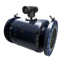
Sensia CALDON SVM 289Ci User Manual (59 pages)
Self-Verifying Ultrasonic Meter with G3 Transmitter
Brand:
Sensia
| Category:
Measuring Instruments
| Size: 6 MB
Table of Contents
Table of Contents
4
Section 1: Introduction
8
Equipment Description
8
SVM 289Ci Meter Body
8
G3 Transmitter
9
Figure 1.1-Example of Meter Body and Transmitter Assembly
9
Table 1.1 Standard K-Factors
10
Model Numbers
11
Meter Body Model Number
11
Transmitter Model Number
12
Transmitter Specifications
13
Table 1.2 SVM 289 Transmitter Specifications
13
Meter Markings
14
Figure 1.2-Meter Body Approvals Nameplate Example
14
Figure 1.3-Meter Body Serial Number Nameplate Example
14
Section 2: Meter Body Installation
15
Lifting/Hoisting the Meter Body
15
Hoist Ring Installation
15
Table 2.1 Hoist Ring Rated Weights and Part Numbers
15
Sling Attachment
16
Figure 2.1-Stainless Steel Bolt and Washer in Tapped Hole of Meter Body End Flange
16
Figure 2.2-Proper Sling Attachment
17
Meter Installation
18
Figure 2.3-Hoist Rings with a Lifting Bar above the Electronics Unit Allow for Uniform Lifting
18
Figure 2.4-SVM 289Ci Installation Recommendations
19
Section 3: Transmitter Connections
20
Transmitter Installation Procedure
20
Transmitter Location
20
Transmitter Terminations
20
Table 3.1 Distance Required from Power Source
20
Figure 3.1-Fully Assembled Transmitter
21
Figure 3.2-User Terminations, Rear View
21
Wiring Instructions
22
Power Terminations (Terminal Block 1)
22
Figure 3.3-DC Power Terminations
22
Figure 3.4-AC Power Terminations
22
Table 3.2 Power Terminations - Recommended 16 to 20 AWG Wire
22
User 1 and User 2 Inputs/Outputs
23
Analog Inputs (Terminal Block 2)
23
Figure 3.5-Power Terminations (TB1 Has Terminals 1 and 2 Only; Safety Earth/Ground Shown in Two Places)
23
Figure 3.6- Typical Analog Input
23
Table 3.3 Analog Inputs (User 1) - Recommend 16 to 28 AWG Wire
23
Analog Outputs (Terminal Block 2)
24
Optional HART (Terminal Block 2)
24
Digital Outputs (Terminal Block 2)
24
Figure 3.7-Typical Analog Output
24
Table 3.4 Analog Outputs (User 2) - Recommended 16 to 28 AWG Wire
24
Table 3.5 Optional HART Output - Recommended 16 to 28 AWG Wire
24
Grounding
25
Figure 3.8-Typical Digital Signals
25
Table 3.6 Digital Signals - Recommended 16 to 28 AWG Wire
25
Figure 3.9-Earth Points on Transmitter Body (Refer to Table 3.7 for Isolated Ground Connections to be Made by User)
26
Table 3.7 Ground Connections Recommended 18 AWG Wire (Internal) and 16 AWG Wire (External)
26
Remote Data Communications
27
Table 3.8 Ethernet Connections (IOP Comparison)
27
Table 3.9 9A-204B169 - TB Copper Connections
27
Serial Communications
28
Figure 3.10-Ethernet Locations
28
Table 3.9 Terminations for Serial Communications - Recommended 16 to 28 AWG Wire
28
Meter Installation Check-Out
29
Output Test Mode
29
Figure 3.11-Typical RS485 Communications
29
Section 4: Understanding Flow Calculations
30
Measuring Flow Velocities
30
Figure 4.1-Illustration of the Transit Time Principle
30
Measuring Flow Rate
31
Figure 4.2-Three Paths Per Chordal Plane as Used in the Caldon SVM
31
Temperature Compensation
32
Conversion to Standard Conditions
32
Figure 4.3- Chordal Planes Used for the Primary Velocity (4-Chord) and Velocity Profile Verification (5-Chord)
32
Section 5: Operations
34
Definitions
34
Figure 5.1-Illustration of Chord, Plane, and Path
34
Normal Operating Conditions
35
Display Leds
35
Display
35
Table 5.1 LED Diagnostics
35
Table 5.2 Display Screens
35
Alarm Conditions
37
Section 6: Maintenance
39
Introduction
39
General Inspections and Preventative Maintenance Procedures
39
Electronic Enclosure Inspection
39
Internal Electronics Inspection
39
Transmitter Troubleshooting
40
Circuit Board Replacement
40
Table 6.1 Circuit Boards
40
IOP - Input/Output and Power Supply Board or Power Fuse Replacement
41
Figure 6.1-Transmitter Components
41
Figure 6.2- Disassembly Views for IOP Replacement
41
Figure 6.3-Location of IOP/F25 Fuse
42
CTC and Display Replacement
43
Figure 6.4-Disassembly Views for CTC and Display Replacement
43
Figure 6.5-SW3 Setting for Use with a 204B169 IOP
45
Figure 6.6-MXR-CTC Ribbon Cable Routing Path
45
MXR Replacement
46
Figure 6.7-Disassembling the Transmitter to Access the MXR
47
Transducer Installation
48
Figure 6.8-Transducer Housing Access Cover
48
Figure 6.9-Transducer Housing Cross-Section
48
Analog Input Verification
49
Figure 6.10-Transducer Housing Detail
49
Analog Output and Pulse Output Verification
50
Force Output (Analog)
50
Force Output (Pulse)
50
Section 7: Troubleshooting and Diagnostics
51
Diagnostics
51
Figure 7.1-Diagnostic Screen
51
Automatic Fault Detection
52
Table 7.1 Signal Diagnostics
52
Section 8: Metrological Seals
54
Figure 8.1-Transmitter with CTC Switch Enabled to Prevent Configuration Changes (Shown Without Tamper Evident Seal for Clarity)
54
Figure 8.2-Seal Wire on Transmitter Enclosure
55
Figure 8.3-Seal Wire on both Ends of a Transmitter
55
Figure 8.4-IOP Tamper-Evident Seals
56
Figure 8.5-Seal Wire on Meter Body
57
Section 9: Recommended Spare Parts
58
Figure 9.1-Transducer Equipment
58
Figure 9.2-Electronic Equipment
58
Advertisement
Advertisement
Related Products
Sensia CALDON SVM 389Ci
Sensia CALDON LEFM CheckPlus-C
Sensia INSTRUCT S30 INTELLIGENT VSD
Sensia 9A-203B050G01
Sensia 9A-203B050G02
Sensia 9A-203B050G03
Sensia 9A-203B050G04
Sensia Barton 306
Sensia Barton 7000 Series
Sensia Barton 71 Series
Sensia Categories
Measuring Instruments
Controller
Control Systems
Laboratory Equipment
DC Drives
More Sensia Manuals
Login
Sign In
OR
Sign in with Facebook
Sign in with Google
Upload manual
Upload from disk
Upload from URL