Table of Contents
Advertisement
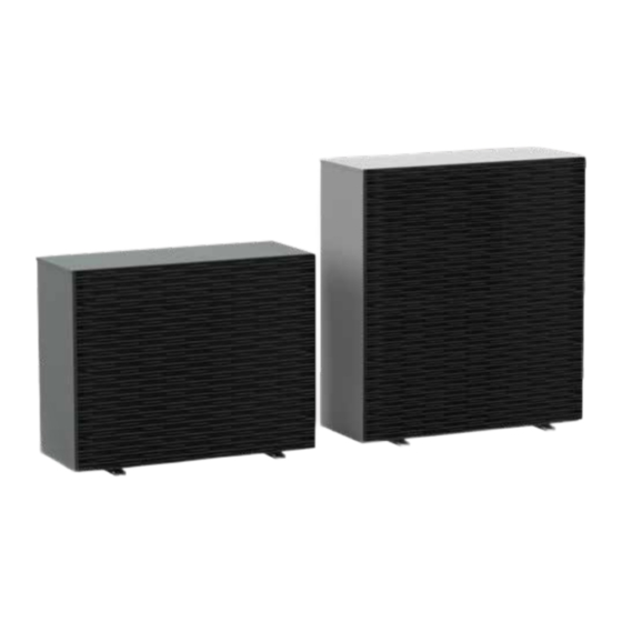
Inverter air/water heat pumps with axial fans
User-installer Manual
Models
i-290 0106
i-290 0109
i-290 0112
i-290 0115
i-290 0118
This manual has been created for informative purpose. The company declines any responsibility for the results of any projecting or any installation based on the explanations and/
or on the technical specifications provided in this manual. It is besides forbidden the reproduction under any form of the texts of the figures contained in this manual. This manual
is a translation from the official italian language version. For reasons of environmental respect the Company will not provide the hard copy in the original language which could be
directly requested or downloaded from the Company website at any time. In case of any dispute, the original language manual will be the trusted one. Even partial reproduction
PROHIBITED © - Advantix SpA
www.maxa.it
R290
Advertisement
Table of Contents

Related Manuals for MAXA i-290 0106


Summary of Contents for MAXA i-290 0106
- Page 1 R290 Inverter air/water heat pumps with axial fans User-installer Manual Models i-290 0106 i-290 0109 i-290 0112 i-290 0115 i-290 0118 This manual has been created for informative purpose. The company declines any responsibility for the results of any projecting or any installation based on the explanations and/ or on the technical specifications provided in this manual.
- Page 2 i-290 Inverter air/water heat pumps with axial fans...
- Page 3 i-290 Inverter air/water heat pumps with axial fans 01-2023 First issue Date Author Approved Note Catalogo / Catalogue / Katalog / Catalogue Serie / Series / Serie / Serie / Série MUI02050120000_00 INVERTER AIR/WATER HEAT PUMPS WITH AXIAL FANS...
-
Page 4: Table Of Contents
5.5.4 Flat roof installation ....................20 5.5.5 Multiple installation ....................20 5.6 DIMENSIONS ......................20 5.6.1 Model i-290 0106 / 0109 ..................20 5.6.2 Model i-290 0112 / 0115 / 118 ................21 5.7 POSITIONING OF CENTRE OF GRAVITY AND VIBRATION DAMPERS ....21 5.8 ACCESS TO THE INNER PART ................... 23 5.8.1 Models i-290 0106 / 0109 .................. - Page 5 Inverter air/water heat pumps with axial fans 5.10.7 Deaerator ......................31 5.11 FUNCTIONAL DIAGRAMS ..................32 5.11.1 i-290 0106 / 0109 ....................32 5.11.2 i-290 0112 / 0115 / 0118 ..................33 5.12 ELECTRICAL CONNECTIONS .................. 33 5.12.1 Access to the electrical panel and user board ............34 5.12.2 Power supply ......................
-
Page 6: Purpose And Contents Of The Manual
i-290 Inverter air/water heat pumps with axial fans The manual of the i-290 units, contains all the necessary information for optimal use of the equipment under safe conditions for the operator. 1. PURPOSE AND CONTENTS OF THE MANUAL This manual provides basic information as to the selection, installation, operation and maintenance of the i-290 unit. It is intended for the oper- ators of the appliance and it enables them to use the equipment efficiently, even if they do not have any previous specific knowledge. -
Page 7: Permitted Use
i-290 Inverter air/water heat pumps with axial fans 3. PERMITTED USE • The company excludes any contractual and extra contractual liability for damage caused to persons, animals or objects, by incorrect instal- lation, setting and maintenance, improper use of the equipment, and the partial or superficial reading of the information contained in this manual. -
Page 8: Workers' Health And Safety
i-290 Inverter air/water heat pumps with axial fans It is strictly forbidden to remove and/or to tamper with any safety device. Children or unassisted disabled persons are not allowed to use the appliance. Do not touch the appliance when barefoot or parts of the body are wet or damp. It is forbidden to perform any cleaning operation when the master switch is ‘ON’. -
Page 9: Personal Protective Equipment
i-290 Inverter air/water heat pumps with axial fans Wear the appropriate PPE (specifically gloves and goggles). Ensure that the operating area is well ventilated. Do not work in closed ambients or ditches with insufficient air circulation. Do not operate on the refrigerant in the vicinity of hot parts or naked flames. Check that there is no voltage and ensure that the unit cannot be reconnected to the power supply during operation. -
Page 10: Warning Labels
i-290 Inverter air/water heat pumps with axial fans Boiling surfaces which can cause burns. Fire hazard. 4.4 WARNING LABELS Warning labels with essential product safety information are applied in the external panels and in the internal parts of the units. The main sym- bols on the labels are the following: Flammable substance symbol (ISO 7010-W021). -
Page 11: Refrigerant Safety Data Sheet
i-290 Inverter air/water heat pumps with axial fans 4.5 REFRIGERANT SAFETY DATA SHEET Name: R290 HAZARDS IDENTIFICATION Highly fl ammable gas. Main hazards: Vapours are heavier than air and can cause asphyxiati on due to reduced oxygen levels. Specifi c hazards: Contact with the liquid can cause frost burns. -
Page 12: Specific R290 Gas Warnings
i-290 Inverter air/water heat pumps with axial fans 4.6 SPECIFIC R290 GAS WARNINGS The R290 refrigerant gas: • is odourless; • is highly flammable (Class A3refrigerant), only if a inignition is present; • it may cause an explosion, but only if a given concentration in air is reached. It is good practice to follow these guidelines: •... -
Page 13: Installation
i-290 Inverter air/water heat pumps with axial fans No smoking near the unit. Transport and storage must be performed in accordance with the national regulations in force. Specifically, according to ADR provisions, the total maximum quantity by transport unit in terms of net mass for flammable gases is 333 kg. In addition, for road transport, use vehicles that are preferably open or equipped with a ventilation system and operated by trained personnel. -
Page 14: Transport And Storage Temperature Limits
i-290 Inverter air/water heat pumps with axial fans The appliance must be placed outside, in a place without continuously operating ignition sources (e.g. open flames, an oper- ating gas appliance or an operating electric heater). Refer to Chapter 5.5. Cable ducts and electrical conduits to the machine must not contain potential ignition sources. Do not perforate or burn. -
Page 15: Lifting Mode
i-290 Inverter air/water heat pumps with axial fans Before commissioning, carefully inspect the unit and packaging for damage or refrigerant leakage. Do not proceed with the start-up of the unit if damage was found during transport. Immediately inform the Company of the problem. - Page 16 i-290 Inverter air/water heat pumps with axial fans Unit installation place must be free from foliage, dust, etc., which could clog or cover the coil. Installation in areas subject to water stagnation or fall, for example from gutters, should be avoided. Also, avoid areas subject to snow accumulation (such as corners of buildings with sloping roofs).
-
Page 17: Danger And Safety Zones
i-290 Inverter air/water heat pumps with axial fans In the event of side-by-side units, the minimum Lmin distance between them is 1 m Covering with canopies or placing near plants or walls should be avoided to prevent air recirculation. In the event of winds stronger than 2.2 m/s the use of wind barriers is recommended. -
Page 18: Free-Field Ground Installation
i-290 Inverter air/water heat pumps with axial fans A safety zone extending beyond the danger zone must also be identified. Within the safety zone, in the event of a refrigerant leak, the concen- tration of the gas in the air is typically below the critical levels for the formation of flammable or hazardous atmospheres. Compliance with the following provisions remains mandatory: •... -
Page 19: Ground Installation In A Corner
i-290 Inverter air/water heat pumps with axial fans MODEL i-290 0106 / 0109 1000 1500 3105 4105 0112 / 0115 / 1500 2000 4105 5105 0118 5.5.3 Ground installation in a corner For units installed on ground in a corner, the danger (continuous red line) and safety zones (dashed black line) are shown in the figures below:... -
Page 20: Flat Roof Installation
For other types of installation not covered in this manual, contact technical support. If in doubt about the installation of the units, request a technical assessment by the fire brigade or a fire prevention expert. 5.6 DIMENSIONS 5.6.1 Model i-290 0106 / 0109 IN/OUT: 1” G E: power supply input. -
Page 21: Model I-290 0112 / 0115 / 118
i-290 Inverter air/water heat pumps with axial fans 1105 70 77 1105 5.6.2 Model i-290 0112 / 0115 / 118 IN/OUT: 1” G E: power supply input. 1105 ___ ___ ____ ____ I I I 5.7 POSITIONING OF CENTRE OF GRAVITY AND VIBRATION DAMPERS The position of the centre of gravity of each machine is indicated in the tables, with reference to the dimensions shown in the image. - Page 22 i-290 Inverter air/water heat pumps with axial fans ___ ___ Shipping Operating Model i-290 L [mm] P [mm] H [mm] Xg [mm] Yg [mm] Zg [mm] weight [kg] weight [kg] 0106 1105 0109 1105 0112 1105 1440 0115 1105 1440 0118 1105 1440...
-
Page 23: Access To The Inner Part
Inverter air/water heat pumps with axial fans 5.8 ACCESS TO THE INNER PART 5.8.1 Models i-290 0106 / 0109 Removal of plastic grille: 1. Unscrew the M5 screws (number 1, 2) using a cross screwdriver. 2. Slide the grille upwards to pull out the interlocking tabs (as shown in detail). -
Page 24: Models I-290 0112 / 0115 / 0118
i-290 Inverter air/water heat pumps with axial fans 5.8.2 Models i-290 0112 / 0115 / 0118 Removal of plastic grille: 1. Unscrew the M5 screws (number 1, 2) using a cross screwdriver. 2. Slide the grille upwards to remove the interlocking tabs. 3. Pull the grille out. 4. Repeat the operations described also for the other grids. -
Page 25: Thermostat Position And Temperature Probe
i-290 Inverter air/water heat pumps with axial fans Removal of side panels: 1. Unscrew the M4 screws (points 4, 5) using a cross screwdriver. 2. Slide the grille upwards to remove the interlocking tabs. 3. Pull the panels forward to remove them. Removing corners: 1. Unscrew the M4 screw (number 6) using a cross screwdriver. -
Page 26: Machine Charging Procedure
i-290 Inverter air/water heat pumps with axial fans There are 5 temperature sensor inside the machine: the return and delivery probes on the water side (position B, C) and those on the compres- sor suction and discharge (position D, E) are located in dedicated wells, while the external air probe (position F) is located on a dedicated support. The probes on the compressor pipes are fixed by clips to the respective thermowells. - Page 27 Check the condition of gaskets and filters frequently. Note that removing the pin considerably reduces the vacuum and charge times of the system; i-290 0106 / 0109 i-290 0112 / 0115 / 0118 • flush the circuit by introducing nitrogen and bringing the pressure up to 4-5 bar. Expel nitrogen from the unit away from heat sources, igni- tion points, wells and other possible stagnation points;...
-
Page 28: Plumbing Connections
i-290 Inverter air/water heat pumps with axial fans Failure to comply with the rules set out in this manual may result in: • malfunctions and loss of machine performance; • leakage of refrigerant gas, with possible formation of an explosion hazard zone; •... -
Page 29: Handbook
i-290 Inverter air/water heat pumps with axial fans FANCOIL to radiant panel from radiant panel to hydronic terminal from hydronic terminal Hydraulic safety group from water supply Glycol fill Num. Description Heat pump Remote control Diverter valve Fancoil Y-filter or dirt separator with integrated filter Expansion tank 5.10.3 Handbook If you need more information about the possible configurations, there is a "Handbook"... -
Page 30: System Load
i-290 Inverter air/water heat pumps with axial fans MODEL i-290 0106 / 0109 / 0112 / 0115 / 0118 < 250 Caution: Do not obstruct the hole in the base panel for condensate drainage. Especially in very cold climate regions, it is recommended to install elevation supports in order to allow ice formation under the unit without damaging it by freezing. -
Page 31: Deaerator
i-290 Inverter air/water heat pumps with axial fans 5.10.7 Deaerator The unit is equipped with a high-efficiency deaerator that continuously captures and eliminates air and any refrigerant gas that may accumulate within the hydraulic circuit, avoiding undesirable effects such as premature corrosion and wear, reduced efficiency and exchange yield, as well as possible contamination of the water by R290 gas. -
Page 32: Functional Diagrams
Inverter air/water heat pumps with axial fans 5.11 FUNCTIONAL DIAGRAMS 5.11.1 i-290 0106 / 0109 EXT1 RD/RS YISV1 INVC RS/RD OUT1 LEGEND CODE NUM. DESCRIPTION CODE NUM. DESCRIPTION INVC VARIALBLE SPEED COMPRESSOR W-OUT WATER SYSTEM OUTLET LINE COIL W-IN WATER SYSTEM INLET LINE... -
Page 33: I-290 0112 / 0115 / 0118
i-290 Inverter air/water heat pumps with axial fans 5.11.2 i-290 0112 / 0115 / 0118 MAF2 MAF1 EXT1 RD/RS YISV1 INVC RS/RD OUT1 LEGEND CODE NUM. DESCRIPTION CODE NUM. DESCRIPTION INVC VARIALBLE SPEED COMPRESSOR W-OUT WATER SYSTEM OUTLET LINE COIL W-IN WATER SYSTEM INLET LINE PLATE HEAT EXCHANGER HIGH PRESSURE TRANSDUCER... -
Page 34: Access To The Electrical Panel And User Board
i-290 Inverter air/water heat pumps with axial fans Before starting any operation, make sure that the power supply is disconnected. The electrical panel is positioned below the cover. Respect the minimum clearances reported in Chapter 5.4 to perform wiring. The installer is responsible to provide an isolating system (e.g. magnetothermal differential circuit breaker) upstream of the unit's electrical connections. - Page 35 i-290 Inverter air/water heat pumps with axial fans 1. After removing the upper grille and cover (as described in Chapter 5.7), unscrew the screws holding the cover in place with a cross screw- driver (number 1, 2). 2. Lift up the electrical panel cover to remove it and proceed with wiring operations. 1. After removing the grilles, cover, side panels and angle brackets (as described in Chapter 5.7), unscrew the highlighted screws holding the cover of the electrical panel with a cross screwdriver.
-
Page 36: Power Supply
i-290 Inverter air/water heat pumps with axial fans 1. Unscrew screw M4 (number 3) using a cross screwdriver. 2. Release the box by first pulling it upwards and then outwards. The above-mentioned operations must be carried out with the machine off and power disconnected (by means of the spe- cific disconnector applied by the installer). -
Page 37: External Module (Gi3)
i-290 Inverter air/water heat pumps with axial fans TERMINAL CONNECTION TYPE Signal connection channel 1 Modbus RTU + remote keyboard Modbus communication for remote keyboard i-CR Signal connection channel 1 Modbus RTU - remote keyboard For signal use shielded twisted pair cable 3 x Signal connection channel 1 Modbus GND remote keyboard 0.75 mm2 (1A = pin 7, 1B = pin 8, 1C = pin9) -
Page 38: Technical Data
i-290 Inverter air/water heat pumps with axial fans 5.13.2 Technical data Technical characteristics Unit Value Supply voltage Supply frequency Maximum power absorption Maximum current for DO Min/Max ambient operating temperature °C -20 / +50 Operating weight 5.13.3 Installation of the external kit (GI3) The product has an IPX4 protection rating and can be installed outdoors. - Page 39 Inverter air/water heat pumps with axial fans 2. Connect the WGI cable from the terminal block to CN13 of the control board as shown in the picture. i-290 0106 / 0109 i-290 0112 / 0115 / 0118 3. Connect the external kit to the heat pump via a cable suitable for modbus communication (cable not supplied, type to be used 3x0.5 mm²).
- Page 40 i-290 Inverter air/water heat pumps with axial fans X-N1 X-L1 X1-1 X2-1 X3-1 X4-1 X5-1 X6-1 X7-1 X8-1 X9-1 X10-1 X11-1 X12-1 X13-1 X14-1 X15-1 X2-2 X3-2 X4-2 X5-2 X10-2 X11-2 X12-2 X13-2 X14-2 X15-2 X1-2 X2-2 X3-2 X4-2 X5-2 X6-2 X7-2 X8-2...
-
Page 41: Control Logics
i-290 Inverter air/water heat pumps with axial fans TERMINAL CONNECTION TYPE X1-1/ X2-1/ X2-2 Connect the mixing valve X3-1/ X3-2 Connect the solar circulator Digital outputs X4-1/ X4-2 Connect the solar drain valve X5-1/ X5-2 Connect the relaunch circulator X6-1/ X6-2 Connect the mixing valve probe X7-1/ X7-2 Connect the ACC. -
Page 42: Shutdowns For Long Periods
i-290 Inverter air/water heat pumps with axial fans The identification plate applied on the machine has all of the technical and performance data of the appliance. In case of tampering, removal or deterioration, ask to the Technical Assistance Service for a copy. Tampering, removal and deterioration of the identification plate complicates installation, maintenance and request for spare parts. - Page 43 i-290 Inverter air/water heat pumps with axial fans It is prohibited to fill the refrigerant circuits with a refrigerant other than that indicated on the identification plate. Using a different refrigerant can cause serious damage to the compressor. It is prohibited to use oils other than those indicated in this manual. Using a different oil can cause serious damage to the compressor.
-
Page 44: Cleaning The Finned Coil
i-290 Inverter air/water heat pumps with axial fans OPERATION M / R month months months months If the unit should be out of service for a long period, drain water from the pipes and from the heat exchanger. This operation is necessary if, during seasonal stoppages, ambient tem- perature is expected to go down below the freezing point of the employed fluid. -
Page 45: Decommissioning
i-290 Inverter air/water heat pumps with axial fans Weight [kg] Unit model Component 0106 0109 0112 0115 0118 Compressor 13,7 13,8 25,7 25,5 25,5 Plate heat exchanger Cu-Al heat exchanger battery 10,7 14,3 22,0 22,0 Liquid receiver Liquid separator Circulator Deaerator Compressor Driver Electric filter... - Page 46 i-290 Inverter air/water heat pumps with axial fans User / Activity Operator User Danger Indication / Instruction Residual risk The procedures for correct unit handling and installation are indicated on the user-installer Mechanical: crushing caused by manual under chapter 5, with in- Failure by the installer to comply the possible instability of the unit dication of the center of gravity,...
- Page 47 i-290 Inverter air/water heat pumps with axial fans User / Activity Operator User Danger Indication / Instruction Residual risk The correct installation proce- The possibility of triggering can- dures are indicated in the user-in- not be eliminated but its proba- Electrical: Fire causes short circuit staller manual under chapter 5.
- Page 48 i-290 Inverter air/water heat pumps with axial fans User / Activity Operator User Danger Indication / Instruction Residual risk Under paragraph 4.1, the us- er-installer manual recommends compliance with current regu- lations (international and local) Ergonomic: fatigue / musculoskel- regarding workers health and Failure to comply with the in- etal disorders caused by exertion safety.
-
Page 49: Technical Data
i-290 Inverter air/water heat pumps with axial fans TECHNICAL DATA 12.1 STANDARD UNIT TECHNICAL SHEET i-290 Unit of measure- TECHNICAL CHARACTERISTICS ment 0106 0109 0112 Cooling capacity (1) 2,10 / 5,43 3,27 / 8,57 / 4,20 / 10,67 / /5,78* 9,20* 11,21* min/nom/max Input power (1) - Page 50 i-290 Inverter air/water heat pumps with axial fans i-290 Unit of measure- TECHINCAL CHARACTERISTICS ment 0115 0118 Cooling capacity (1) 5,11 / 13,75 / 5,11 / 12,41 / 13,47* 14,33* min/nom/max Input power (1) 3,71 4,34 E.E.R. (1) 3,35 3,16 Cooling capacity (2) 7,90 / 13,94 / 7,86 / 12,9 / 14,40*...
-
Page 51: Unit And Auxiliary Electrical Data
i-290 Inverter air/water heat pumps with axial fans Performance referring to the following conditions, according to standard UNI EN 14511:2022: (1) Cooling: outdoor air temperature 35°C; in/out water temperature 12/7°C. (2) Cooling: outdoor air temperature 35°C; in/out water temperature 23/18°C. (3) Heating: outdoor air temperature 7°C db 6°C db;... -
Page 52: Heating Water Production (Winter Mode)
i-290 Inverter air/water heat pumps with axial fans 13.3 HEATING WATER PRODUCTION (WINTER MODE) When the system has reached steady state, the water inlet temperature must not drop below 22°C: lower values, not due to transient phases or reaching steady-state, can cause system failures and could possibly break the compressor. The maximum outlet water temperature must not exceed 75°C. - Page 53 i-290 Inverter air/water heat pumps with axial fans COOLING MODE i-290 Cooling Ta [°C] DOMESTIC HOT WATER MODE i-290 Sanitary mode Ta [°C]...
-
Page 54: Remote Control Interface
i-290 Inverter air/water heat pumps with axial fans REMOTE CONTROL INTERFACE 14.1 GENERAL INFORMATION The i-CR is a Modbus remote control with negative LCD and capacitive keys.The device is to be used as a remote machine keyboard with local temperature detection and replication of on-board control functionality. The remote control: •... -
Page 55: I-Cr Connections
i-290 Inverter air/water heat pumps with axial fans 14.4 I-CR CONNECTIONS Two connection cables are required between chiller unit or heat pump and i-CR remote control: • 3X1.5mmq shielded twisted pair cable for Modbus R+/R-/GND communication. • 2x1.5mmq cable for 12Vac power supply. DESCRIPTION TERMINALS i-CR UNIT TERMINALS... -
Page 56: Display
i-290 Inverter air/water heat pumps with axial fans DESCRIPTION It allows you to move to a higher menu or to increase the value of a parameter. DOWN It allows you to move to a lower menu or to decrease the value of a parameter. CHRONOTHERMOSTAT Allows to set the operating bands for thermostation on the room temperature detected by the probe present in the i-CR. - Page 57 i-290 Inverter air/water heat pumps with axial fans ICON DESCRIPTION NOTE Off mode Off mode (from manual or chrono-programme band). Indicates that you have access to menus under a password. Password active The dots next to it indicate the password level entered. Padlock Indicates active keypad lock.
- Page 58 ADVANTIX SpA Via S. Giuseppe Lavoratore 24, 37040 Arcole (VR) Italy Tel. (+39).045.76.36.585 E-mail: info@advantixspa.it www.maxa.it...
Need help?
Do you have a question about the i-290 0106 and is the answer not in the manual?
Questions and answers