Table of Contents
Advertisement
Advertisement
Table of Contents

Related Manuals for MAXA i-MAX 0466


Summary of Contents for MAXA i-MAX 0466
- Page 2 i-MAX Industrial inverter air/water heat pump with axial fans 03-2019 M.S. A.B. Alignment with Ver415 REV 005 S03 07-2018 M.S. A.B. Functions updating 09-2017 D.M. A.B. 10-2017 A.B. F.M. Date Author Supervisor Notes Serie / Series / Serie / Serie / Série Catalogo / Catalogue / Katalog / Catalogue i-MAX (SSL) 0466 -06115 MCO01110H8120-03...
-
Page 3: Table Of Contents
i-MAX Industrial inverter air/water heat pump with axial fans INDEX CONSERVATION OF THE MANUAL ............................5 GRAPHIC SYMBOLS USED IN THE MANUAL ..........................5 PERMITTED USES ................................... 5 GENERAL SAFETY GUIDELINES ..............................5 PERSONAL PROTECTION EQUIPMENT ............................ 5 HEALTH AND SAFETY OF WORKERS ............................5 PURPOSES AND CONTENTS OF THE MANUAL ......................... - Page 4 i-MAX Industrial inverter air/water heat pump with axial fans ALARM SIGNALIZATION ................................ 18 ............................18 EAT PUMP LOCKOUT SIGNALIZATION ENABLEMENT OF DOMESTIC HOT WATER PRODUCTION (DHW) ..................18 9.5.1 MEMORIZATION OF THE SENSOR IN HEATING MODE ....................19 9.5.2 SANITARY MODE CALLING FROM DIGITAL INPUT ......................19 9.5.3 HEATING MODE ON DOMESTIC HOT WATER TANK .....................
-
Page 5: Conservation Of The Manual
i-MAX Industrial inverter air/water heat pump with axial fans 1 CONSERVATION OF THE MANUAL The manual has to be always kept for future reference. It has to be stored in a safe place, away from dusts and moisture. It has to be available and accessible to all users who shall consult it any time they are in doubt on how to operate the equipment. -
Page 6: Purposes And Contents Of The Manual
i-MAX Industrial inverter air/water heat pump with axial fans WARNING: Before proceeding, you should read the user’s-installer manual accompanying the appliance. All the operations described below must be carried out only by QUALIFIED PERSONNEL. The wiring to the terminal block must be performed by qualified personnel. Any routine and/or not-routine maintenance operation shall be carried out when the equipment has been shut down, disconnected from electric power supply. -
Page 7: User - Onboard Controller Interface
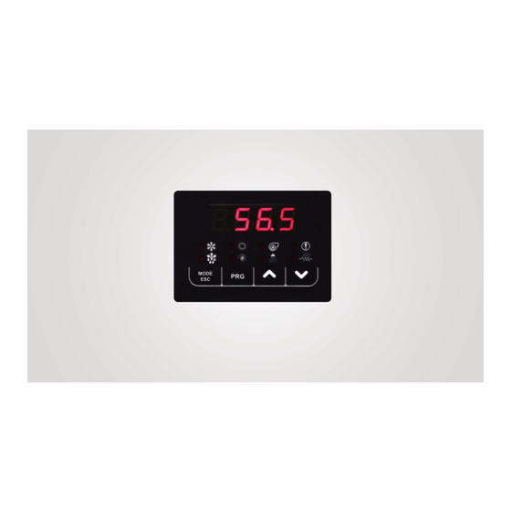
i-MAX Industrial inverter air/water heat pump with axial fans 5 USER – ONBOARD CONTROLLER INTERFACE In normal visualization, the 7 segment display with 4 digits shows the regulating temperature in tenths of degrees or the warning code if at least one alarm is active. The type of visualization in the menu mode page is depending on the position where you are. Labels and codes are used to help the user to identify the settings of the display. -
Page 8: Menu Contents
i-MAX Industrial inverter air/water heat pump with axial fans Level 1 (M) = it’s visible if you enter the maintainer or manufacturer password Level 2 (C) = it’s visible if you enter the manufacturer password Level 3 (A) = it’s visible only via Modbus MENU CONTENTS The main functions of the menus are listed below, especially when there are some unambiguous functions. -
Page 9: Parameters Menu
i-MAX Industrial inverter air/water heat pump with axial fans 5.2.6 Parameters menu The parameters are collected into groups; each group is identified by a three-digit code, while the index of each parameter is preceded by a letter. DESCRIPTION GROUP’S IDENTIFICATIVE CODE PARAMETER’S INDEX VISIBILITY Configuration... -
Page 10: Led Status Description
i-MAX Industrial inverter air/water heat pump with axial fans 5.2.10 LED STATUS DESCRIPTION • ON if the compressor is running Compressor LED • OFF if the compressor is off • FLASHING if timings are in progress waiting for compressor’s start up. •... -
Page 11: Dynamic Set-Point Control
i-MAX Industrial inverter air/water heat pump with axial fans DYNAMIC SET-POINT CONTROL The controller allows change the set-point by adding a value depending on the temperature of the outdoor air sensor. This function can be used if necessary by modify the parameter values, following the below information (it is the installer’s responsibility to change the parameters). -
Page 12: Operation Under Thermoregulator Call (Default)
i-MAX Industrial inverter air/water heat pump with axial fans 7.2.1 OPERATION UNDER THERMOREGULATOR CALL (Default) During this operating mode (P03=1), the thermo-regulator actuates the circulator; after a time delay of P01 seconds from the circulator pump startup, the compressor also will turn ON. However, during the power off status, the circulator pump turns off with a delay of P02 minutes after shutdown status by mean of the thermo-regulator (the shutdown status is corresponding to the off status of the compressor). -
Page 13: Air Purging Of The System
i-MAX Industrial inverter air/water heat pump with axial fans Example in cooling operation: If the difference in temperature between water inlet and outlet is greater than P09 + P10, the pump will run at maximum speed. If the difference temperature between water inlet and outlet is less than P09 - 0.2°C, the pump will run the minimum speed. In the other cases, the pump modulates trying to match the temperature difference with P09. -
Page 14: Inverter Compressors Control In Cooling Mode
i-MAX Industrial inverter air/water heat pump with axial fans 7.3.4 INVERTER COMPRESSORS CONTROL IN COOLING MODE The management of the compressors depends on the ambient temperature and on the water temperature setpoint. The PI type regulation with: • ST = regulation temperature sensor •... -
Page 15: Safe Time Periods
i-MAX Industrial inverter air/water heat pump with axial fans 7.3.6 SAFE TIME PERIODS The compressors respect the minimum waiting time for the turning on and off actions (regardless of their configurations and if they are inverters or ON/OFF type). C01 = Minimum Off time of a compressor # 240 sec (default). C02 = Minimum time between two start-up of the same compressor # 360 sec (default). -
Page 16: Fan Speed Control In Heating Mode
i-MAX Industrial inverter air/water heat pump with axial fans 7.5.3 FAN SPEED CONTROL IN HEATING MODE The fan speed control in heating mode follows the diagram shown below, where: F10 = Delta cut-off of the fan in cooling/heating mode F11 = Cut-off hysteresis in cooling/heating mode F15 = Minimum fan speed in heating mode F16 = Maximum silent fan speed in heating mode F17 = Set pressure for the minimum fan speed in heating mode... -
Page 17: Remote On/Off
i-MAX Industrial inverter air/water heat pump with axial fans outlet water sensor exceeds r02+r06 in heating mode or r03+r06 in cooling mode and in shut off condition (the default value is r06=2,0°C). The heating cable placed on the basement of the appliance turns on when the outdoor air temperature decreases below 3°C and the unit starts the defrosting cycle (or if r19=0 even if the unit is not in defrosting cycle, or in stand-by mode). -
Page 18: Alarm Signalization
i-MAX Industrial inverter air/water heat pump with axial fans 9.3 ALARM SIGNALIZATION It is possible to configure an under-voltage output for alarm signalization. To enable this function, enter at the page of the parameters PRGPSS PRG (introduce the maintainer password) PRGPAr... -
Page 19: Memorization Of The Sensor In Heating Mode
i-MAX Industrial inverter air/water heat pump with axial fans If H10 = 2/4/6, the remote on-off function disenables the production of domestic hot water and also the operation of the − heat pump in heating and cooling on plant side. 9.5.1 MEMORIZATION OF THE SENSOR IN HEATING MODE In the case of commutation from water users to the domestic hot water, the temperature sensor commutates from a "water outlet temperature sensor"... -
Page 20: Auxiliary Electric Heater
i-MAX Industrial inverter air/water heat pump with axial fans AUXILIARY ELECTRIC HEATER In some configurations of some plant systems, it could be necessary the use an auxiliary electric heater for the system and/or DHW sides. To define the mode of using of the auxiliary electric heaters for plant system and DHW side, you must set the parameter “r24” as below. -
Page 21: Management Of The Circulator With Active Electric Heater
i-MAX Industrial inverter air/water heat pump with axial fans 2. r14=1, the electric heaters will be activated one excluding the other: 2.1. r20=0, the priority is for the plant side (the sanitary heater will operate only if the thermoregulation for the heater of plant side is achieved);... -
Page 22: In Joint Operation (Band Ii)
i-MAX Industrial inverter air/water heat pump with axial fans The activation priorities are defined by the parameters r14, r20, r23 and r24. The operation becomes normal if the temperature increases above the value given by r22+1,0°C. Note: In the joint operation, the temperature of the boiler is controlled by the water temperature remote sensor of the plant circuit (if enabled), particularly if the temperature measured by the remote sensor is less than the setpoint Hea, the boiler will be activated, and then will be deactivated when the measured temperature by the remote sensor is greater than setpoint Hea. -
Page 23: Operation Area - Activation Of The Auxiliary Electric Heater And Boiler (Plant Circuit Water Temperature Sensor Is Not Enabled)
i-MAX Industrial inverter air/water heat pump with axial fans 9.10.5 OPERATION AREA - ACTIVATION OF THE AUXILIARY ELECTRIC HEATER AND BOILER (Plant circuit water temperature sensor is not enabled) The possible configurations of the parameters related to auxiliary heaters are listed below in the tables 1, 2, 3 and 4, that are divided by areas of operation (the columns of the items "MODE"... - Page 24 i-MAX Industrial inverter air/water heat pump with axial fans 1) Heat pump 2) After r15 minutes, auxiliary Set up of HEAT+SAN SANITARY electric heater of sanitary minutes 3) After r15 minutes later, boiler 1) Heat pump 2) After r15 minutes, boiler Set up of HEAT+SAN SANITARY...
- Page 25 i-MAX Industrial inverter air/water heat pump with axial fans TABLE 4. SUBSTITUTION OPERATION ORDER OF INTERVENTION N° HEATING ELEMENTS (when the set- MODE OPERATION point is not achieved) 1) Boiler HEAT / Set up of 2) After r12 minutes, auxiliary HEAT 0/1/2 HEAT+SAN...
-
Page 26: Auxiliary Systems Offset Management
i-MAX Industrial inverter air/water heat pump with axial fans The below Table (6) shows the behavior of the auxiliary electric heaters of both sanitary and plant in all cases where the unit is operating. TABLE 6. OPERATION OF AUXILIARY ELECTRIC HEATERS N°... -
Page 27: Adjustable Setpoints
i-MAX Industrial inverter air/water heat pump with axial fans To activate the function enter with maintainer password to the parameters: Parameter Unit Default Value Description Terminals Notes Digital input for second setpoint ID3E – ID3E Under voltage output single Under-voltage output for 3 way valve DO5E(phase) phase 230Vac, 50Hz, 5A resistive, for radiant panels... -
Page 28: Setpoint Configuration Parameters
i-MAX Industrial inverter air/water heat pump with axial fans The parameters can be activated and/or modified by the user or by entering the installer password in the controller that is located on the front panel of the unit. DESCRIPTION GROUP IDENTIFICATIVE CODE INDEX OF THE PARAMETER VISIBILITY Configuration... -
Page 29: Condensation Parameters
i-MAX Industrial inverter air/water heat pump with axial fans 11.5 CONDENSATION PARAMETERS Parameter Description Unit Default Range Visibility Allowed configurations Notes Operation under compressor call 0 ÷1 INSTALLER Min fan speed 0 ÷100 INSTALLER Max silent fan speed in cooling mode Based on the model 0 ÷100 INSTALLER... -
Page 30: Water With Glycol
i-MAX Industrial inverter air/water heat pump with axial fans 0 = Function not active 3 = Remote selection for Summer/Winter mode Configuration of the digital input 0÷26 INSTALLER 19= Secondary circulator thermostat ID3E, ID3E terminals ID3E 26 = Double set point 28 = Sanitary mode call 0 = Function not active 1 = Classic mode... -
Page 31: Alarms Management
i-MAX Industrial inverter air/water heat pump with axial fans 13 ALARMS MANAGEMENT When getting access to ERR alarm’s menu, you can display the active alarms collected in two directories ALL C1 for circuit 1 and ALL C2 for circuit 2, under the alarm list. 13.1 E000 –... -
Page 32: E801÷E971] Timeout Inverter
i-MAX Industrial inverter air/water heat pump with axial fans 13.14 [E801÷E971] TIMEOUT INVERTER The time out alarm indicates that the control of the system is lost. The alarm will be activated when the controller does not communicate with the compressor driver board. 13.15 POWER FAILURE After power supply reset: •... -
Page 33: Heat Pump Lockout Alert
i-MAX Industrial inverter air/water heat pump with axial fans 13.16.1 HEAT PUMP LOCKOUT ALERT The alarm will surge immedialtely in the below cases and once the corresponding conditions are fulfilled: Alarm Recovery condition Permanence condition E001 Manual E002 Manual E005 Manual E006 Manual... - Page 34 i-MAX Industrial inverter air/water heat pump with axial fans...
- Page 36 ADVANTIX SpA Via S. Giuseppe Lavoratore 24, 37040 Arcole (VR) Italy Tel. (+39).045.76.36.585 E-mail:info@advantixspa.it www.maxa.it...
Need help?
Do you have a question about the i-MAX 0466 and is the answer not in the manual?
Questions and answers