Advertisement
Parts in the box

Fig 1
| # | Item |
| 1 | Reach IP At‐Home Alarm unit |
| 2 | AC Adapter including UK & EU mains plug options |
| 3 | Connector Cover for mounting the Reach IP flat |
| 4 | Stand for mounting the Reach IP vertically |
| 5 | Screw for fixing the Stand or Connector Cover |
| 6 | Touch Pendant & Wearing Options (neck cord/wrist strap/belt clip) |
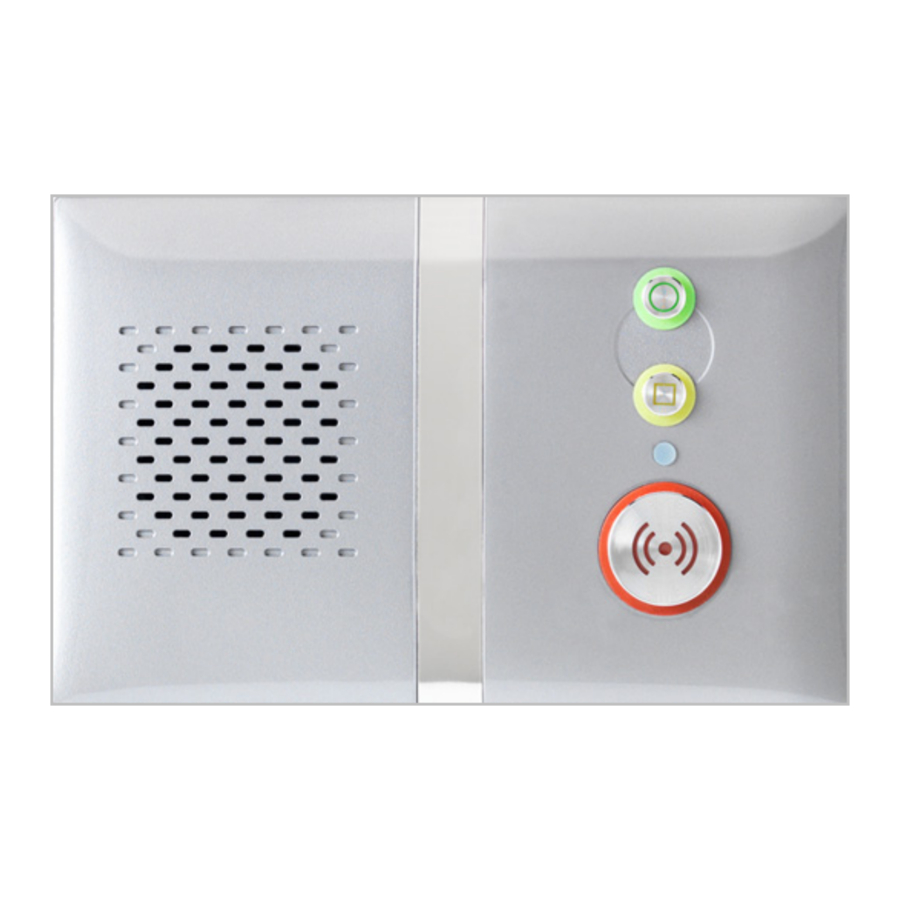
Buttons, Status LED & Connections

Rear Connector Area

Fig 2
| # | Function |
 | Red Alarm Button: make an emergency call |
 | Green Cancel Button: cancel an emergency call made in error |
 | Yellow Function Button: toggle Home/Away mode (if enabled) |
 | Black Power Button: on/off and enter Control Mode/Service Menu |
 | Status LED: off is normal (Green no signal, Red alarm, Amber fault) |
| SUPPLY | 5V DC input from AC Adapter |
| USB | Programming Port (factory use only) |
| ETHERNET | Connection to the Internet via a Router (future upgrade) |
Touch Pendant Wearing Options

Fig 3
The Touch Pendant is a portable alarm trigger that can be worn around the neck, on the wrist or clipped to a belt. The Pendant is already registered to the Reach IP unit and ready to use, just fit the desired wearing option as described below;
- Neck Cord: lie the cord through one of the grooves on the rear on the Pendant then slide the neck cord attachment into place. Note: smaller cord end marked
![]() in Fig 3.
in Fig 3. - Wrist Strap: feed the wrist strap (pattern side up) through the 2 slots in the wrist strap attachment.
![warning]() Note: locate the pip marked
Note: locate the pip marked ![]() in the centre hole
in the centre hole ![]() in Fig 3.
in Fig 3.
Push the aluminium fixing stud through the hole marked![]() at the end of the strap.
at the end of the strap. - Belt Clip: simply clip into place on the rear of the Pendant. Note: the suction cup can be fitted to the belt clip to stick the Pendant to a hard surface, e.g. a tiled wall.
 in Fig 3.
 in the centre hole
  in Fig 3.
 at the end of the strap.
Setting‐up the Reach IP unit
- Plug the AC Adapter into the mains supply.
- Plug the AC Adapter Lead into the Reach IP unit SUPPLY port.
- Switch the mains supply on at the wall, press and hold the
![]() Power button for a couple of seconds until the 3 front buttons illuminate briefly then release. The Red Alarm button will remain lit if illumination is enabled (default) and the Status LED will be lit green until a GSM signal is established then it will go out.
Power button for a couple of seconds until the 3 front buttons illuminate briefly then release. The Red Alarm button will remain lit if illumination is enabled (default) and the Status LED will be lit green until a GSM signal is established then it will go out. ![]()
range test the Pendant from all extremes of the home- Make an alarm call to the Alarm Receiving Centre (ARC) to check operation.
 Power button for a couple of seconds until the 3 front buttons illuminate briefly then release. The Red Alarm button will remain lit if illumination is enabled (default) and the Status LED will be lit green until a GSM signal is established then it will go out.
Making an Alarm Call
Press the  Alarm button and the unit will announce "calling for help ‐ please wait" when an alarm call is being made. The Alarm button will flash red. It is possible to cancel the alarm within the first 5 seconds by pressing the
  Cancel button.
Control Mode & Service Menu
The Reach IP is normally in idle mode; Control Mode and Service Menu are ways of easily reconfiguring the unit. The unit will return to idle mode after a change is made or after 5 seconds of inactivity.
Control Mode Functions
Enter Control Mode by pressing the  Power button once, the unit will beep and the
  and
and  buttons will illuminate. The Control Mode functions are listed below;
| # | Control Mode Functions |
 | Red Alarm Button: toggle Red Alarm Button illumination on/off |
 | Green Cancel Button: change speech and sounds volume |
 | Yellow Function Button: enter Service Menu (see below) |
Service Menu Functions
Once in Control Mode, press and hold  until the unit announces the first Service Menu function "add radio device" then release, the button will be flashing. Press the button to sequentially step through the functions, press the
  button to select the required function. The Service Menu functions are listed below;
| # | Service Menu Functions |
| 1 | Add Radio Device |
| 2 | Range Test Mode (also includes GSM Signal Strength Mode) |
| 3 | Delete Radio Devices |
| 4 | Home/Away Activity Function |
Toggle Red Alarm Button Illumination
Press the  Power button to enter Control Mode then press and hold until the unit announces the new Red Button state e.g. if the illumination was ON then it will announce "function is disabled" and illumination will now be off, if it was OFF then it will announce "function is enabled" and illumination will now be on.
Change Speech and Sounds Volume
Press the Power button to enter Control Mode then then press and hold  until the unit sounds a number of beeps to indicate its SPEECH volume setting ‐ continue holding to cycle through the 3 settings and release on the required setting. Press and hold again within 5 seconds to change the SOUND level setting.
Add Radio Device
Press the Power button to enter Control Mode then press and hold  until the unit announces "add radio device" then release. Press the button to confirm then activate the radio device. The unit will sound a high beep if it's a new device and announce "range test mode" ‐ press to confirm, or press to step to the next function, or press to exit the mode and the unit will announce the next function.
 Note: if the device already exists a low beep will sound.
Range Test Mode
Press the Power button to enter Control Mode then press and hold until the unit announces "add radio device" then release. Press again and the unit will announce "range test mode" then press to confirm. The and buttons will be flashing. Go to all extremes of the home and press the Pendant, the Reach IP will respond with a beep and the Pendant button will flash green if the signal is received. Press to exit the mode and the unit will announce the next function.
GSM Signal Strength Indication
During Range Test Mode the Status LED will indicate the GSM signal strength, see table below;
| GSM Signal Strength | RSSI | Status LED |
| High | 21‐31 | Solid Green |
| Good | 11‐20 | 0.1 Sec Flashing Green |
| Low | 1‐10 | 0.5 Sec Flashing Green |
| No Signal | 0 | Not Lit |
Delete Radio Devices
Press the  Power button to enter Control Mode then press and hold
  until the unit announces "add radio device" then release. Repeatedly press until the unit announces "delete radio devices" then press
  to confirm. Activate the radio device to be removed and a beep will be heard. Press and hold until a beep is heard, and the unit will announce the next function.
Deleting ALL Radio Devices
Press the Power button to enter Control Mode then press and hold until the unit announces "add radio device" then release. Repeatedly press until the unit announces "delete radio devices" then press to confirm. Press and hold until a beep is heard then release. Press and hold again until a beep is heard, and the unit will announce the next function.
Home/Away Activity Function
Press the Power button to enter Control Mode then press and hold until the unit announces "add radio device" then release. Repeatedly press until the unit announces "home away activity function" then press to confirm. The unit will announce its current state; "function is disabled" or "function is enabled". To change the setting press and hold until the unit announces the new state, the unit will then announce the next function. Note: if enabled the Function Button is used in idle mode to toggle Home/Away mode.
Error Indications
An error is indicated by a "blurp" or a voice message; e.g. "power disconnected" or "GSM network failure". This will repeat every 2 minutes until the problem is resolved or the  button is pressed to silence the warning. Errors are also indicated on the Status LED, see the table below;
| Status LED | Possible Reason | Suggested Action |
| Solid Green | No GSM network signal | Check GSM network signal strength |
| Flashing Red | Mains failure | Check mains supply and/or AC adapter connection |
| Solid Amber | Battery failure or not charging | Check/replace battery |
| Flashing Green/Red/Amber | Radio Interference | Check interfering radio sources. Move DECT phones, WiFi Routers etc. at least 1 metre away from the Reach IP |
Switching the Reach IP Off
The Reach IP uses very little power and should always be left switched on. If the unit is being removed and stored for a prolonged period, then it should be switched off. Press and hold the  Power button until all 3 front buttons and the Status LED flash once then release; the unit is now switched off.
Important Information
It is very important to read and understand this section before use.
Keep these instructions in a safe place for future reference.
Use & Maintenance
- Operating Temperature Range: +5 to +45°C
- Do not damage the unit or its parts, if damaged contact your supplier immediately
- Do not expose to direct sunlight
- Keep away from dust, moisture and dirt
- Do not drop, knock, twist or shake the device
- Do not warm up the device or use it near a fire
Cleaning
- All parts in the Reach IP kit can be cleaned with a mild soap solution and a damp cloth. Dry with a soft dry cloth.
- Strong chemicals and other harsh substances must not be used when cleaning or handling the parts in the Reach IP kit.
- The Reach IP must be disconnected from the mains supply before cleaning.
- After cleaning, confirm that the unit works properly by making a test alarm call to the Alarm Receiving Centre.
Safety Notes
- Read instructions before use
- Always test the product as per the instructions before use
- Always check the function of the product after making changes to settings
- This product may not be suitable for all persons and should not be a substitute for the routine visual monitoring by a Carer.
- This product must not be used in situations where a delay in the arrival of appropriate medical care could lead to a potentially life‐threatening situation.
- Test the product regularly and replace when necessary.
- Do not integrate with other systems other than those specified by the manufacturer.
- Always keep the product dry, exposure to excessive moisture can cause malfunction.
- This product will not cause electromagnetic disturbances under normal working conditions.
- This product can be placed near other products or devices as long as mechanical vibration is not present.
- Remove the battery if the unit is to be out of use or stored for an extended period.
Disposal

The crossed‐out wheelie bin symbol on the product indicates it is classed as Electrical or Electronic Equipment and should not be disposed of in commercial waste at its end of life.
The Waste of Electrical & Electronic Equipment (WEEE) Directive (2012/19/EU) has been put in place to recycle products using the best available recovery and recycling techniques to minimize impact on the environment, treat hazardous substances and avoid increased landfill. For product disposal please contact your supplier to check the terms and conditions of the purchase contract. Always ensure this product is not mixed with commercial waste for disposal.
Specification
- Reach IP complies with the Social Alarm Standard: EN 50134‐3:2012
- Dimensions: 120mm x 187mm x 38mm (HxWxD)
- Weight: 455 grams (exc PSU)
- Pendant Frequency: 869.2125MHz
- Max transmission power: 50.000 μV/m
- Protocols: TS 50134‐9 (SCAIP), BS8521 & TT92
- Power Supply: 100‐240VAC 50/60Hz <5 Watts
- AC Adapter Type: KSAS0050500100D5D (5V DC 1.0A Rated)
- Battery Type: 3.6V NiMH 1000mAh
Tynetec is a business unit of Legrand Electric Ltd, Unit 10 Cowley Road, Blyth Riverside Business Park, Blyth, Northumberland, NE24 5TF, UK. Tel: +44 (0) 1670 352371
Web: www.tynetec.co.uk

Documents / Resources
References
Download manual
Here you can download full pdf version of manual, it may contain additional safety instructions, warranty information, FCC rules, etc.
Advertisement


Need help?
Do you have a question about the Reach IP and is the answer not in the manual?
Questions and answers