Advertisement
Quick Links
Reach IP
At‐Home Alarm
User Guide
Fig 1: Parts in the box
AC Adapter with
UK & EU Plugs
Reach IP unit
Stand
Connector
Cover
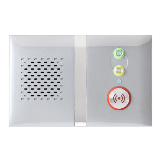
Fig 2: Buttons, Status LED & Connections
Green
Cancel Button
Power Button
Yellow
Function
Button
Status
LED
Red
Alarm Button
Trusted Technology
Fig 3: Touch Pendant Wearing Options
Caring for People
Touch
Pendant
Neck Cord with
Safety Break
1.0 Parts in the box (see Fig 1)
#
Item
1
Reach IP At‐Home Alarm unit
2
AC Adapter including UK & EU mains plug options
3
Connector Cover for mounting the Reach IP flat
4
Stand for mounting the Reach IP vertically
5
Screw for fixing the Stand or Connector Cover
6
Touch Pendant & Wearing Options (neck cord/wrist strap/belt clip)
2.0 Buttons, Status LED & Connections (see Fig 2)
#
Function
Red Alarm Button: make an emergency call
Green Cancel Button: cancel an emergency call made in error
Yellow Function Button: toggle Home/Away mode (if enabled)
Black Power Button: on/off and enter Control Mode/Service Menu
Status LED: off is normal
5V DC input from AC Adapter
SUPPLY
Programming Port (factory use only)
USB
Touch Pendant &
Connection to the Internet via a Router (future upgrade)
ETHERNET
Wearing Options
3.0 Touch Pendant Wearing Options (see Fig 3)
The Touch Pendant is a portable alarm trigger that can be worn around the neck, on
the wrist or clipped to a belt. The Pendant is already registered to the Reach IP unit
Screw for
and ready to use, just fit the desired wearing option as described below;
Stand/Cover
Neck Cord: lie the cord through one of the grooves on the rear on the Pendant then
slide the neck cord attachment into place. Note: smaller cord end marked in Fig 3.
Wrist Strap: feed the wrist strap (pattern side up) through the 2 slots in the wrist
strap attachment. Note: locate the pip marked in the centre hole in Fig 3.
Push the aluminium fixing stud through the hole marked at the end of the strap.
Belt Clip: simply clip into place on the rear of the Pendant. Note: the suction cup can
be fitted to the belt clip to stick the Pendant to a hard surface, e.g. a tiled wall.
Rear Connector Area
3.1 Setting‐up the Reach IP unit
Black
Supply
1. Plug the AC Adapter into the mains supply.
Port
2. Plug the AC Adapter Lead into the Reach IP unit SUPPLY port.
3. Switch the mains supply on at the wall, press and hold the Power button for a
couple of seconds until the 3 front buttons illuminate briefly then release. The Red
Alarm button will remain lit if illumination is enabled (default) and the Status LED will
be lit green until a GSM signal is established then it will go out.
4. IMPORTANT: range test the Pendant from all extremes of the home ‐ see section 4.4
Ethernet
USB
5. Make an alarm call to the Alarm Receiving Centre (ARC) to check operation.
Port
Port
Aluminium
Fixing Stud
Wrist Strap
Neck Cord
Attachment
Attachment
Suction
Wrist Strap
Cup
Belt Clip
Attachment
(Green
no signal, Red
alarm, Amber
fault)
3.2 Making an Alarm Call
Press the Alarm button and the unit will announce "calling for help ‐ please wait"
when an alarm call is being made. The Alarm button will flash red. It is possible to
cancel the alarm within the first 5 seconds by pressing the Cancel button.
4.0 Control Mode & Service Menu
The Reach IP is normally in idle mode; Control Mode and Service Menu are ways of
easily reconfiguring the unit. The unit will return to idle mode after a change is made
or after 5 seconds of inactivity.
Control Mode Functions
Enter Control Mode by pressing the Power button once, the unit will beep and the
and buttons will illuminate. The Control Mode functions are listed below;
#
Control Mode Functions
Red Alarm Button: toggle Red Alarm Button illumination on/off
Green Cancel Button: change speech and sounds volume
Yellow Function Button: enter Service Menu (see below)
Service Menu Functions
Once in Control Mode, press and hold until the unit announces the first Service
Menu function "add radio device" then release, the button will be flashing. Press
the button to sequentially step through the functions, press the button to select
the required function. The Service Menu functions are listed below;
#
Service Menu Functions
1
Add Radio Device
2
Range Test Mode (also includes GSM Signal Strength Mode)
3
Delete Radio Devices
4
Home/Away Activity Function
4.1 Toggle Red Alarm Button Illumination
Press the Power button to enter Control Mode then press and hold until the unit
announces the new Red Button state e.g. if the illumination was ON then it will
announce "function is disabled" and illumination will now be off, if it was OFF then it
will announce "function is enabled" and illumination will now be on.
4.2 Change Speech and Sounds Volume
Press the Power button to enter Control Mode then then press and hold until the
unit sounds a number of beeps to indicate its SPEECH volume setting ‐ continue
holding to cycle through the 3 settings and release on the required setting. Press
and hold again within 5 seconds to change the SOUND level setting.
4.3 Add Radio Device
Press the Power button to enter Control Mode then press and hold until the unit
announces "add radio device" then release. Press the button to confirm then
activate the radio device. The unit will sound a high beep if it's a new device and
announce "range test mode" ‐ press to confirm, or press to step to the next
function, or press to exit the mode and the unit will announce the next function.
Note: if the device already exists a low beep will sound.
4.4 Range Test Mode
Press the Power button to enter Control Mode then press and hold until the unit
announces "add radio device" then release. Press again and the unit will announce
"range test mode" then press to confirm. The and buttons will be flashing.
Go to all extremes of the home and press the Pendant, the Reach IP will respond with
a beep and the Pendant button will flash green if the signal is received. Press to exit
the mode and the unit will announce the next function.
Advertisement

Related Manuals for Tynetec Reach IP


Summary of Contents for Tynetec Reach IP
- Page 1 3.2 Making an Alarm Call Trusted Technology Press the Alarm button and the unit will announce “calling for help ‐ please wait” Fig 3: Touch Pendant Wearing Options Caring for People Aluminium when an alarm call is being made. The Alarm button will flash red. It is possible to Fixing Stud Touch Wrist Strap cancel the alarm within the first 5 seconds by pressing the Cancel button. Pendant Neck Cord Attachment Attachment 4.0 Control Mode & Service Menu The Reach IP is normally in idle mode; Control Mode and Service Menu are ways of Suction Wrist Strap Reach IP Cup easily reconfiguring the unit. The unit will return to idle mode after a change is made Neck Cord with or after 5 seconds of inactivity. Safety Break Belt Clip ...
- Page 2 The Waste of Electrical & Electronic Equipment (WEEE) Directive (2012/19/EU) has Battery failure Solid Amber Check/replace battery been put in place to recycle products using the best available recovery and recycling or not charging techniques to minimize impact on the environment, treat hazardous substances and Check interfering radio sources. Move Flashing Radio DECT phones, WiFi Routers etc. at avoid increased landfill. For product disposal please contact your supplier to check the Green/Red/Amber Interference least 1 metre away from the Reach IP terms and conditions of the purchase contract. Always ensure this product is not mixed with commercial waste for disposal. 6.0 Switching the Reach IP Off The Reach IP uses very little power and should always be left switched on. If the unit is being removed and stored for a prolonged period, then it should be switched off. Press and hold the Power button until all 3 front buttons and the Status LED flash once then release; the unit is now switched off. Tynetec is a business unit of Legrand Electric Ltd, Unit 10 Cowley Road, Blyth Riverside Business Park, Blyth, Northumberland, NE24 5TF, UK. Doc No. FM0802 V1.04 Tel: +44 (0) 1670 352371 Web: www.tynetec.co.uk ...
Need help?
Do you have a question about the Reach IP and is the answer not in the manual?
Questions and answers