
Related Manuals for Tynetec Reach Plus


Summary of Contents for Tynetec Reach Plus
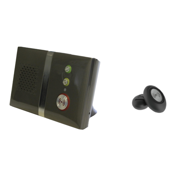
- Page 1 Reach Plus At‐Home Alarm Unit Touch Personal Pendant USER & INSTALLATION GUIDE www.tynetec.co.uk ...
-
Page 2: Table Of Contents
SECTION 1 – USER INSTRUCTIONS Section Topic Page 1.1 Important Information 3 1.2 Unpacking the Reach Plus At‐Home Alarm 3 1.3 The Touch Personal Pendant 4 1.4 Connecting the Reach Plus At‐Home Alarm 5 1.5 Reach Plus and Extension Telephones 6 1.6 Reach Plus and Broadband 6 1.7 Switching the Reach Plus At‐Home Alarm on 7 1.8 Switching the Reach Plus At‐Home Alarm off 7 1.9 Making an Emergency Call 8 1.10 Accidental Calls 9 1.11 Answering an incoming Telephone Call 9 1.12 Using the Personal Recipient Mode 10 1.13 ... -
Page 3: Important Information
1.1 IMPORTANT INFORMATION The users telephone MUST BE connected to the Reach Plus TEL socket – a double adapter on the incoming line must not be used. If the user has extension telephones care should be taken to ensure that these are also connected via the Reach Plus TEL socket. Failure to connect the users telephones as described above may cause difficulties with alarm calls – if in doubt seek advice. If the user has a DECT telephone the base station MUST BE at least 2 metres away from the Reach Plus. Failure to provide this separation may result in reduced range of personal pendants or other radio devices. All telephone equipment has a Ringer Equivalence Number (REN) which is used to calculate the number of items that can be connected to a single telephone line. A REN of 4 is the maximum allowed on a standard UK telephone line ‐ the Reach Plus has a REN of 1 If the REN total of all equipment connected to a telephone line exceeds 4 the equipment may not operate REN 1 correctly. With different types of equipment there is no guarantee of correct operation even if the REN is less than 4. Typically 1 or 2 standard telephones (REN 1) can be used with the Reach Plus. Avoid using strong detergents or polish when cleaning the Reach Plus unit or Touch pendant. Wipe clean with a damp cloth and polish with a dry duster. 1.2 UNPACKING THE REACH PLUS AT‐HOME ALARM The Reach Plus At‐Home Alarm is supplied with a Power Lead, a Telecom Lead, a Touch Pendant and a wearing kit. A stand can be fitted if the unit is being mounted upright or a connector cover if it is being placed flat. The stand/cover must be fixed with the screw provided. ... -
Page 4: The Touch Personal Pendant
Making an Emergency Call… Simply press the Touch pendant button once. The button will FLASH RED (( )) for several seconds to confirm a call is being made. The Reach Plus will announce “Pendant alarm – Please wait, dialling for assistance” The Touch pendant battery should last for about 3‐5 years depending on use. The battery condition is checked every day, if the voltage falls and stays below a preset level for 7 consecutive days a “low battery” call will automatically be sent to the Control Centre. Pendants must be returned to Tynetec for battery replacement. ‐ 4 ‐ ... -
Page 5: Connecting The Reach Plus At-Home Alarm
1.4 CONNECTING THE REACH PLUS AT‐HOME ALARM The Reach Plus At‐Home alarm unit should only be installed and programmed by trained personnel. Reach Plus Basic Connections… AT‐HOME ALARM UNIT TELEPHONE BT WALL SOCKET MAINS ELECTRICITY SUPPLY C/O SUPPLY TELECOM LEAD POWER LEAD The Reach Plus will usually be table mounted within 3metres of a mains supply and the master telephone socket. If extension cables are used care should be taken to ensure that no one can trip over the leads. Installation Procedure… 1. Unplug the users Telephone from the BT wall socket and plug it into the Reach Plus TEL socket. If the user has a DECT cordless telephone, extension telephone sockets in other rooms or Broadband see sections 1.1, 1.5 and 1.6 for more information. 2. Connect the Telecom Lead between the Reach Plus C/O socket and the BT wall socket (where the users telephone was originally plugged in). 3. Connect the Power Lead between the Reach Plus ... -
Page 6: Reach Plus And Extension Telephones
1.5 REACH PLUS AND EXTENSION TELEPHONES It is very important that all telephones in the home are connected to the Reach Plus TEL socket. This method of connection ensures that an alarm call on the Reach Plus unit will always disconnect any other equipment that might cause connection difficulties. EXTENSION TELEPHONE MAIN TELEPHONE REACH REACH PLUS AT-HOME ALARM UNIT AT-HOME ALARM UNIT MASTER TELEPHONE SOCKET SECONDARY SECONDARY SOCKET TELEPHONE WITH SOCKET DOUBLE ADAPTER INCOMING TELEPHONE LINE 1.6 REACH PLUS AND BROADBAND Broadband Service Providers will supply a filter module to plug into the telephone line to allow connection of a computer and a normal telephone. Only one filter module is required to connect the computer, telephone and Reach Plus when configured as shown below; USERS TELEPHONE... -
Page 7: Switching The Reach Plus At-Home Alarm On
1.7 SWITCHING THE REACH PLUS AT‐HOME ALARM ON Connect the power lead and switch the mains supply on, the front light will flash RED/AMBER/GREEN for about 12 seconds… (( )) (( )) When the front light goes STEADY GREEN the Reach Plus ... -
Page 8: Making An Emergency Call
1.9 MAKING AN EMERGENCY CALL An emergency call can be made at any time of the day or night. 1. Press the RED (( )) button on the Reach Plus unit or press the Touch pendant... The pendant button will OR FLASH RED (( )) for a few seconds after the ... -
Page 9: Accidental Calls
1.10 ACCIDENTAL CALLS If an emergency call is made by accident it can be cancelled by pressing the GREEN button once. The unit will announce “Alarm cancelled” and the front light will return to STEADY GREEN. “Alarm cancelled” Please note once the Reach Plus starts to dial the call cannot be cancelled. Advise the user not to worry if they don’t manage to cancel an accidental call – when the control centre answers they just need to say the call was made accidently. The staff will be pleased that they have talked and they will cancel the call in the normal way. 1.11 ANSWERING AN INCOMING TELEPHONE CALL The Reach Plus can also be used to answer a normal incoming telephone call… (( )) ... -
Page 10: Using The Personal Recipient Mode
1.12 USING THE PERSONAL RECIPIENT MODE The Reach Plus can be set to dial up to 4 different personal recipients (e.g. relatives or friends). The personal recipient telephone numbers (PR1‐PR4) must be programmed – see section 2.3.5 A personal recipient message must be recorded – see section 2.3.8 To answer a personal recipient call… When the telephone rings, press the Green line key “Beep… Beep…” (or pick‐up) and answer in the normal way. RING If the call is from the Reach Plus unit you will hear a single “Beep” every 2 seconds. ... -
Page 11: Using The Activity Monitoring Mode
1.13 USING THE ACTIVITY MONITORING MODE Optional PIR movement detectors can be installed in the home to monitor if the resident is “up and about” each day. If no movement is detected by the end of an activity monitoring period an inactivity alarm call will be sent to the control centre. If the resident is going away from home the Reach Plus should be put into “Away Mode” to prevent inactivity calls being sent to the control centre. See section 1.15 for how to use the Away Mode. If no movement is detected the unit will announce… (( )) “Inactivity alarm” (( )) The GREEN button will FLASH GREEN and the message will repeat for 60 seconds. Press the FLASHING GREEN button once within 60 seconds… ... -
Page 12: Using The I'm Ok Mode
1.14 USING THE I’M OK MODE The Reach Plus can be set to flash its GREEN button and sound a beep for a preset time period each day. If the resident is “up and about” and feeling “OK” they can press the GREEN button to stop the alert. If the GREEN button has not been pressed before the end of the I’m OK period an inactivity call will be sent to the control centre. If the resident is going away from home the Reach Plus should be put into “Away Mode” to prevent inactivity calls being sent to the control centre. See section 1.15 for how to use the Away Mode. During the I’m OK period… (( )) The GREEN button will FLASH GREEN (( )) once per second. ... -
Page 13: Using The Away Mode
1.15 USING THE AWAY MODE If activity monitoring or I’m OK mode is being used and the resident is going away from home they must select “Away Mode” to prevent in‐activity calls being sent to the control centre. Press the YELLOW button and the unit will announce… “Away” (( )) The front light will FLASH GREEN The unit is now in Away Mode – activity monitoring and I’m OK mode is turned off. When the resident returns home they must remember to turn activity monitoring and I’m OK back on... Press the YELLOW button and the unit will announce… “Home”... -
Page 14: Using The Intruder Mode
1.16 USING THE INTRUDER MODE If optional PIR movement detectors are fitted for activity monitoring the resident can use these devices as a basic intruder alarm when they go out. 1. Press the GREEN button and the unit will announce… “Intruder mode …Ready” 2. Press the TOUCH PENDANT within 20 seconds and the unit will announce… “Enabled” ‐ “Beep‐Beep” “Beep‐Beep”….. ... -
Page 15: Using The Reminder Mode
1.17 USING THE REMINDER MODE The Reach Plus can be set to play a reminder message at the same time every day, once a week or once a month. Up to 8 different messages, maximum 8 seconds duration each, can be recorded by a Carer or relative using the microphone in the unit. The reminder message will repeat for 30 seconds or it can be silenced by pressing the GREEN button. When it’s time a reminder message will play… “Don’t forget to take your pills this morning” (( )) (( )) The GREEN button will FLASH GREEN and the reminder will repeat for 30 seconds. Press the FLASHING GREEN button once… ... -
Page 16: Using The Door Monitoring Mode
1.18 USING THE DOOR MONITORING MODE If optional door contacts are fitted the Reach Plus can be set to play a message and/or raise an alarm when an entrance door is opened. Up to 16 different messages, maximum 8 seconds duration each, can be recorded by a Carer or relative using the microphone in the unit. The Reach Plus can be set to monitor the door permanently or during 3 preset time periods each day. If the entrance door is opened during a monitored period… “The front door is open” The message will repeat for 30 seconds. Press the GREEN button once… ... -
Page 17: Using The Lone Worker Mode
1.19 USING THE LONE WORKER MODE The Reach Plus can be set to sound an alert after a preset time interval has elapsed. The user has 60 seconds to press the GREEN button to stop the alert and re‐start the time interval again. If the GREEN button is not pressed after 60 seconds an inactivity call will be sent to the control centre. At the end of the Lone Worker interval… “Beep‐Beep‐Beep..” (( )) (( )) The GREEN button will FLASH GREEN and the unit will “Beep” for 60 seconds. ... -
Page 18: Mains Power Failure Alert
1.20 MAINS POWER FAILURE ALERT The Reach Plus will make the resident aware if their mains electricity is off or if the power lead has been accidently unplugged... (( )) The front light will FLASH AMBER and the unit will announce… “Please check your mains supply” This message will repeat 3 times every 4 hours until the mains power is restored. ... -
Page 19: Battery Failure Alert
Press the GREEN button to SILENCE the message The low battery condition is automatically reported to the control centre and they will arrange to visit and replace the battery. In normal use the battery should not need replacing for between 3 to 5 years. The replacement battery must be identical to that originally fitted and should only be changed by a competent person. Replacement battery: Tynetec Part No. F00141 1.23 ON/OFF SWITCH The Reach Plus can be switched off if it is not going to be used for a prolonged period. Remove the stand (if fitted) to access the battery cover on the rear. Undo the screw, remove the cover and carefully lift the battery out of its compartment. ... -
Page 20: Quick Start Guide
2.1 QUICK START GUIDE This Quick Start Guide takes you through the most basic set‐up possible when installing a Reach Plus. This assumes the Reach Plus will be dialling a control centre (not a personal recipient) and all other settings are factory default. Connecting the Reach Plus… 1. Unplug the users Telephone from the BT wall socket and plug it into the Reach Plus TEL socket. 2. Connect the Telecom Lead between the BT wall socket and the Reach Plus C/O socket. 3. Connect the Power Lead between a mains socket and the Reach Plus SUPPLY socket. Power‐up and Enter Program Mode… 1. Switch the mains supply on ‐ the front light on the Reach Plus will flash RED/AMBER/GREEN. 2. Enter 1 6 7 0 using the keypad on the rear, the unit will announce “Program Mode – Ready” and the front light will FLASH FAST GREEN. Setting the Unit ID Number… 1. Enter # 0 2 4 and the unit will announce “Unit ID”. 2. Enter the unit ID number followed by the # key. 3. The unit will announce “Ready”. Setting the Telephone Number… 1. Enter # 0 2 6 and the unit will announce “Telephone Number 1”. 2. Enter the control centre telephone number followed by the # key. 3. The unit will announce “Ready”. Note: up to 4 different telephone numbers can be entered using codes #027, #028 & #029. Setting the Protocol Type… 1. Enter # 0 2 2 and the unit will announce “Protocol Type”. 2. Enter 0 # for TT or 1 # for BS8521 or 2# for BS7369. 3. The unit will announce “Ready”. ... -
Page 21: Programming Mode
2.2 PROGRAMMING MODE The keypad on the rear of the Reach Plus is used to program the unit ID, control centre telephone number, protocol type, time & date etc. It may be necessary to remove the stand to access the keypad. Enter 1 6 7 0 using the keypad on the rear… (( )) The front light will FLASH FAST GREEN and the unit will announce… ... -
Page 22: Setting The Telephone Number
2.2.2 SETTING THE TELEPHONE NUMBER The telephone number will be issued by the control centre (max 12 digits). Press # 0 2 6 and the unit will announce... “Telephone number 1” Enter the telephone number then press # If the number was entered correctly you will hear the “Ready” prompt. ... -
Page 23: Setting The Time & Date
2.2.4 SETTING THE TIME & DATE The time & date must be set so all events are logged with the correct time and all timed functions operate correctly. Press # 0 4 4 and the unit will announce... “Set Time” Enter the time as 4 digits using the 24 hour clock format (e.g. 1:30PM is 1330) followed by #. If the time was entered correctly you will hear ... -
Page 24: Programming Parameters List
2.3 PROGRAMMING PARAMETERS LIST Enter Default See Menu Group Parameter Enter the following data… Parameter No. Setting Section Load Defaults #000 N/A Load System Defaults #001 N/A Enter the required default parameter Load Defaults 2.3.1 Load Radio Defaults #002 N/A followed by # Load Log Defaults #018 Load Message Defaults #019 Siren Volume #005 Level 3 Enter 0 to 5 followed by # Audio Volume #006 Level 3 0# = off, 5# = max volume Ring Volume #007 Off Audio Settings 2.3.2 ... - Page 25 2.3 PROGRAMMING PARAMETERS LIST ‐ CONTINUED Enter Default See Menu Group Parameter Enter the following data… Parameter No. Setting Section GSM Mode #004 0# = Disable or 1# = Enable Disabled Safe Call Setup #039 0# = Disable or 1# = Enable Disabled 0 = Disable or 1 = Enable Disabled Optional Settings 2.3.9 Intruder Mode Setup #063 Entry time 000 to 999 Secs 30 Sec Entry Exit time 000 to 999 Secs then # 30 Sec Exit Tx Event to Data Collector #043 0# = Disable or 1# = Enable Disabled Change Security Code #125 Enter new 4 digit code followed by # 1670 Enter 8 digit ID, ...
-
Page 26: Load Defaults
2.3.1 LOAD DEFAULTS Load Defaults – clears all parameter settings, radio devices, Telecare data and recorded messages from the Reach Plus memory. Enter #000, the unit will announce “Load Defaults” then press #. Load System Defaults – clears all parameter settings from the Reach Plus memory. Enter #001, the unit will announce “Load System Defaults” then press #. Load Radio Defaults – clears all radio devices from the Reach Plus memory. Enter #002, the unit will announce “Load Radio Defaults” then press #. Load Log Defaults – clears all stored Telecare data from the Reach Plus memory. Enter #018, the unit will announce “Load Log Defaults” then press #. Load Message Defaults – clears all recorded messages from the Reach Plus memory. Enter #019, the unit will announce “Load Message Defaults” then press #. 2.3.2 AUDIO SETTINGS Siren Volume – the volume of all alarm messages and dial‐out tones can be set between 0 (off) and 5 (highest). Enter #005, the unit will announce “Siren Volume”, press 0 to 5 followed by #. Audio Volume – the speech volume to/from the control centre can be set between 0 (off) and 5 (highest). Enter #006, the unit will announce “Audio Volume”, press 0 to 5 followed by #. Ring Volume – the volume of the internally generated ring tone (this is only used if there is no telephone connected to the TEL socket) can be set between 0 (off) and 5 (highest). Enter #007, the unit will announce “Ring Volume”, press 0 to 5 followed by #. Audio Mode – allows the control centres method of switching the speech to be set. Simplex means the speech direction is manually switched whereas Half Duplex is voice switched. Note; always check with the control centre which method they prefer to use. Enter #008, the unit will announce “Audio Mode”, press 0# for Simplex or 1# for Half Duplex. Mains Fail Alert – allows the audible “Please Check Your Mains Supply” message to be turned on/off. A mains failure is reported to the control centre after a random delay between 1 and 4 hours. Enter #009, the unit will announce “Mains Disconnection Alert”, press 0# to Disable or 1# to Enable. Assurance Tone – allows the audible “Please Wait – Dialling for Assistance” message and dial‐out tones to be turned on/off. Enter #010, the unit will announce “Assurance Tone”, press 0# to Disable or 1# to Enable. ... -
Page 27: Hardwired Inputs & Output
2.3.3 HARDWIRED INPUTS & OUTPUT Up to four hardwired input devices can be connected to the Reach Plus using the optional hardwired input lead (Tynetec Part No. ZSA555) or hardwired I/O unit (Tynetec Part No. ZSA556). All input devices must have normally open clean contacts which close on alarm except PIR’s which must have normally closed clean contacts which open on alarm. A change‐over clean contact relay output is available with the optional hardwired I/O unit (Tynetec Part No. ZSA556). The relay can be activated from the control centre during a call. The DTMF tone used to activate the relay and the duration it remains latched is programmable. Both the hardwired input lead and the hardwired I/O unit plug into Reach Plus DATA socket. Hardwired Input 1 – enter #101, the unit will announce “Hardwired Input 1 – Trigger Type” Enter the device type (0 to 9) from the list below; 0 Not Assigned 1 Pullcord 2 Smoke Detector 3 PIR Detector 4 Door Contact 5 High Temp 6 Low Temp 7 Gas Detector 8 Heat Detector 9 CO Detector ... -
Page 28: Identity Settings
2.3.4 IDENTITY SETTINGS Protocol Type – check with the control centre which protocol type they use. Enter #022, the unit will announce “Protocol Type” press 0# for TT or 1# for BS8521 or 2# for BS7369. BS7369 Interval – if BS7369 protocol is selected you can change the data interval for use on different Mobile networks. Enter #023, the unit will announce “BS7369 Interval Time”, enter the time required in mS as a 4 digit number (0001 to 9999) followed by #. Unit Identity – the unique ID number issued by the control centre to identify the users name, address and personal details. Enter #024, the unit will announce “Unit ID”, enter the ID number (maximum 12 digits) followed by #. Pre‐Alarm Delay – the time allowed for an emergency call to be cancelled (by the GREEN button) before the Reach Plus starts to dial the control centre. Enter #025, the unit will announce “Pre‐Alarm Delay”, enter the delay in seconds 00 (no delay), 04, 08, etc. to 60 in 4 second intervals followed by #. 2.3.5 TELEPHONE NUMBERS ARC1 to ARC4 – these are the Alarm Receiving Centre (control centre) telephone numbers. Enter #026, the unit will announce “Telephone Number 1”, enter the telephone number (max 16 digits) followed by #. Repeat for ARC telephone numbers 2, 3 & 4. Enter a between digits to incur a pause in dialling. To delete a telephone number enter the Parameter Number followed by #. For example to delete ARC3 enter #028#. PR1 to PR4 – these are the Personal Recipient (relative/friend) telephone numbers. Enter #030, the unit will announce “Telephone Number 5”, enter the telephone number (max 16 digits) followed by #. Repeat for PR telephone numbers 6, 7 & 8. If PR telephone numbers are used a “unit identity message” should be recorded – see section 2.3.8. ARC1 to ARC4 Dial Attempts – the number of times each ARC telephone number will be dialled if it gets an engaged tone on the first attempt. Enter #03826, the unit will announce “Telephone Number 1 Dial Attempts”, press 1 to 9 followed by #. Repeat for ARC telephone numbers 2, 3 & 4. PR1 to PR4 Dial Attempts – the number of times each PR telephone number will be dialled if it gets an engaged tone on the first attempt. Enter #03830, the unit will announce “Telephone Number 5 Dial Attempts”, press 1 to 9 followed by #. Repeat for PR telephone numbers 6, 7 & 8. ... -
Page 29: Activity Monitoring
2.3.6 ACTIVITY MONITORING The activity monitoring mode allows the Reach Plus to monitor residents movement over 3 preset periods per day and automatically report an alarm at the end of each period if there has been no activity (or less activity than the preset minimum threshold). The activity threshold can range from 00 to 99 – this is the minimum number of PIR activations you would expect to see during the activity monitoring period. Enable/Disable – a PIR detector (hardwired or radio) must be fitted if activity monitoring is being enabled. Enter #034, the unit will announce “Activity Monitoring”, press 0# to Disable or 1# to Enable. Activity Period 1 Setup – set activity monitoring period 1 start time, threshold and stop time. Enter #0351, the unit will announce “Activity Monitoring Setup 1 – Start Time” Enter the start time as 4 digits using the 24 hour clock format (e.g. 7AM is 0700) The unit will announce “Threshold” Enter the threshold as a 2 digit number (00 to 99) The unit will announce “Stop Time”. Enter the stop time as 4 digits using the 24 hour clock format (e.g. 10AM is 1000) followed by #. Activity Period 2/3 Setup – enter #0352/#0353 to set activity monitoring periods 2/3 and follow the same procedure as above. Inactivity Reminder – if the inactivity reminder is enabled an “inactivity alarm” message will play at the end of the monitored period if no activity (or less than the preset threshold) has occurred. The user has 60 seconds to confirm activity by pressing the GREEN button once, if the button is not pressed an inactivity alarm will be reported. Enter #071, the unit will announce “Inactivity Reminder”, press 0# to Disable or 1# to Enable. Lone Worker Interval – if the lone worker interval is set the unit will start to beep after the preset time interval has elapsed. The user has 60 seconds to confirm they are OK by pressing the GREEN button once, if the button is not pressed an inactivity alarm will be reported. Enter #072, the unit will announce “Lone Worker”, enter the interval as a single digit in hours (1 to 9) followed by # or enter 0# to disable the feature. I’m OK Setup – if the I’m OK feature is set the unit will flash its GREEN button and sound a beep during a preset time period each day. During this period the user can press the GREEN button once to declare themselves “OK”. If the button is not pressed an inactivity alarm will be reported after a ... -
Page 30: Periodic Test
2.3.7 PERIODIC TEST The Reach Plus has the option to perform an automatic test call on a preset interval between 1 and 99 days. The time the test call is made is also programmable. Note: the user will not know when a test call is being performed, the dial‐out is silent and no speech is heard. Periodic Test – set the interval between test calls and the time of day you want the call to be made. Enter #036, the unit will announce “Periodic Test – Interval” Enter 2 digits (01 to 99) for the interval between test calls in days The unit will announce “Time” Enter the test call time as 4 digits using the 24 hour clock format (e.g. 8PM is 2000) followed by #. Note: do not set multiple Reach Plus units with a periodic test call to the same control centre with the same interval and time. Try and choose a “quiet” time of the day to send the test call. To disable a periodic test set the interval as 00. 2.3.8 MESSAGES SET‐UP The internal microphone on the Reach Plus unit can be used to record a personal recipient message and up to 16 other general messages. Each message is limited to a maximum of 8 seconds duration. It is important that a clear, preferably high pitched, voice is used at normal conversation level – do not shout. The message should be spoken clearly and deliberately so that it will be easily understood by the alarm recipient. Record ID Message – allows a personal recipient message to be recorded. This message will be heard over the phone by the person that answers the emergency call. Enter #060, the unit will announce “Record ID Message” After the countdown of 3 beeps speak your message (max 8 secs) Press # to end recording or the unit will announce “Ready” when the record time has expired. Play ID Message – the personal recipient message will be played‐back. Enter #061, the unit will announce “Play ID Message”, after the single beep your message will be heard. Delete ID Message – the personal recipient message will be deleted. Enter #062, the unit will announce “Delete ID Message”, after the single beep press #. ... -
Page 31: Options Setup
The unit will announce “Acknowledge” Enter 1 for Yes or 0 for No; if set as 1 (Yes) the GREEN button can be pressed to silence the reminder message, if set as 0 (No) the reminder will repeat for 60 seconds then stop. The unit will announce “Alarm” Enter 1# for Yes or 0# for No; if set as 1# (Yes) then an inactivity alarm will be reported after 60 seconds if the reminder is not acknowledged by pressing the GREEN button. If set as 0# (No) then the reminder message will repeat for 60 seconds only. Enter #092 to #098 to setup reminders 2 to 8. For example: to set a reminder every Tuesday for lunch club at 11:45AM, acknowledgement is required with an alarm call to the control centre if it is not acknowledged… The message has been recorded by a family member in message number 2 slot Enter #091 02 (message slot 2) and the unit announces “Time” Enter 1145 (11:45AM in the 24 hour format) and the unit announces “Interval” Enter 1 (for weekly interval) and the unit announces “Day” Enter 2 (for Tuesday) the unit announces “Acknowledge” Enter 1 (for yes to require acknowledgement) and the unit announces “Alarm” Enter 1 (for yes to alarm) then press # and the unit announces “Ready” The reminder settings have been saved. 2.3.9 OPTIONS SET‐UP GSM Mode – this mode should only be enabled if the Reach Plus is being connected via the Mobile network using a GSM unit rather than a conventional PSTN land line. This prevents a telephone line fault being detected when the GSM unit goes into low power mode during a mains failure. Enter #004, press 0# to Disable or 1# to Enable. Safe Call Setup – Safe Call devices (Tynetec Part No. ZSA260) must be plugged in‐line with all telephones within the home if this option is enabled. These devices ensure the Reach Plus always takes control of the telephone line in an emergency situation. Enter #039, the unit will announce “Safe Call Setup”, press 0# to Disable or 1# to Enable. ‐ 31 ‐ ... -
Page 32: Radio Device Setup
2.3.9 OPTIONS SET‐UP ‐ CONTINUED Intruder Mode Setup – a PIR movement detector must be installed if intruder mode is being enabled. Enter #063, the unit will announce “Intruder Mode” Enter 0# to disable or 1 to enable, if you press 1 to enable the unit will announce “Entry Time” Enter the entry time in seconds as 3 digits (000 to 999) The unit will announce “Exit Time” Enter the exit time in seconds as 3 digits (000 to 999) followed by #. Change Security Code – the 4 digit security code required to enter programming mode via the keypad on the rear of the Reach Plus can be changed. Enter #125 and the unit will beep once, enter a new 4 digit code followed by #. Transmit Event to Data Collector – if enabled all events are transmitted on the Reach Plus data port for collection and analysis. Enter #043, the unit will announce “Transmit Event to Data Collector”, press 0# to Disable or 1# to Enable. 2.3.10 RADIO DEVICE SET‐UP For Reach Plus units set on BS8521 protocol each radio device can be assigned a “Location Code” to allow the control centre operator to identify the exact location of the device in alarm. 00 Not Assigned 13 Living Area 26 Utility Room 2 39 Games Room 52 Garden Other 01 Local Unit 14 Dining Room 1 27 Entrance/Lobby 40 Common Room 1 ... - Page 33 Enter 1 for Yes or 0 for No; if set as 1 (Yes) the GREEN button can be pressed to silence the alarm message, if set as 0 (No) the message will repeat for 60 seconds The unit will announce “Alarm” Enter 1 for Yes or 0 for No; if set as 1 (Yes) then an emergency call will be initiated when the input is activated, if set as 0 (No) then the alarm message will repeat for 60 seconds only The unit will beep, activate another radio device to be learned or press # to end. Radio devices can be set to only activate alarm calls during preset times (activity windows) each day. If they are activated outside these time periods the event is logged in the Reach Plus memory. Up to 3 activity windows can be set per device, they repeat every day and they can be set through midnight. Trigger Activity Window – allows a radio device to be learned automatically, have its location code, acknowledge & alarm parameters and activity windows assigned. Enter #051, the unit will announce “Learn Radio Device and Enter Location Code” Activate the radio device – the unit will announce “Device Type – Enter Location Code” Enter a 2 digit location code from the table above The unit will announce “Message Number” Enter a recorded message number (01 to 16) or enter 00 if no message is required The unit will announce “Acknowledge” Enter 1 for Yes or 0 for No; if set as 1 (Yes) the GREEN button can be pressed to silence the alarm message, if set as 0 (No) the message will repeat for 60 seconds The unit will announce “Alarm” Enter 1 for Yes or 0 for No; if set as 1 (Yes) then an emergency call will be initiated when the input is activated, if set as 0 (No) then the alarm message will repeat for 60 seconds only The unit will announce “Start Time 1” Enter start time 1 as 4 digits using the 24 hour clock format (e.g. 7AM is 0700) The unit will announce “Stop Time 1” Enter stop time 1 as 4 digits using the 24 hour clock format (e.g. 10AM is 1000) The unit will announce “Start Time 2”, enter start time 2 or if not required press # to exit. Trigger Action – only relevant to Carer pendants (Tynetec Part No. ZXT607), this allows attendance times to be logged in local memory with an alarm call to the control centre or to be logged in local memory only. If a Carer pendant is learned via the GREEN button you will get log and alarm setup. Enter #050, the unit will announce “Learn Radio Device and Enter Location Code” Activate the Carer pendant and the unit will announce “Trigger Action” Enter 0# for log and alarm or 1# for log only. ‐ 33 ‐ ...
-
Page 34: Buttons And Led Setup
2.3.11 BUTTONS AND LED SET‐UP The 3 push buttons, their illuminated halos and the tricolour status indicator light on the front of the Reach Plus unit can be individually enabled or disabled. Enter #064, the unit will announce “Program Red Button”, enter 0# to Disable or 1# to Enable. Enter #065, the unit will announce “Program Yellow Button”, enter 0# to Disable or 1# to Enable. Enter #066, the unit will announce “Program Green Button”, enter 0# to Disable or 1# to Enable. Enter #067, the unit will announce “Program Red LED”, enter 0# to Disable or 1# to Enable. Enter #068, the unit will announce “Program Tricolour LED”, enter 0# to Disable or 1# to Enable. Enter #069, the unit will announce “Program Yellow LED”, enter 0# to Disable or 1# to Enable. Enter #070, the unit will announce “Program Green LED”, enter 0# to Disable or 1# to Enable. 2.3.12 TIME & DATE SET‐UP The Reach Plus has a real time clock which must be set for all timed functions to operate correctly. Set Time – allows the time to be set. Enter #044, the unit will announce “Set Time” Enter the time as 4 digits using the 24 hour clock format (e.g. 1:30PM is 1330) followed by #. Set Date – allows the day/date/month/year to be set. Enter #045, the unit will announce “Set Date” Enter as 7 digits using the format; Day (1 = Mon to 7 = Sun), Date (01 to 31), Month (01 to 12), Year (00 to 99) followed by #. For example; Wednesday 25 January 2012 would be 3250112#. BST Setup – if enabled the British Summer Time +/‐ 1 hour clock changes will be made automatically every March and October. Enter #046, the unit will announce “BST Setup”, enter 0# to Disable or 1# to Enable. 2.3.13 CHECK PARAMETERS The Reach Plus programming can be checked by entering parameter check codes, all settings for each ... -
Page 35: Programming Via The Control Centre
2.3.13 CHECK PARAMETERS ‐ CONTINUED Check Reminders – enter #084, the unit will announce “Check Reminders” followed by all settings listed in section 2.3.8. Check Optional Settings – enter #085, the unit will announce “Check Optional Settings” followed by all settings listed in section 2.3.9. Check Time & Date – enter #086, the unit will announce “Check Time & Date” followed by all settings listed in section 2.3.12. Check Trigger Window – enter #087, the unit will announce “Check Trigger Window” followed by all settings listed in section 2.3.10 (page 33). 2.4 PROGRAMMING VIA THE CONTROL CENTRE The Reach Plus can be programmed from a control centre using TT or BS8521 protocol. If the Reach Plus has been programmed previously you should “Load System Defaults“ before attempting to re‐program via the control centre – see section 2.3.1. Follow either of the methods below; 2.4.1 BY RINGING INTO THE CONTROL CENTRE 1. Ensure that the Reach Plus is connected correctly and switched on 2. Use the telephone connected to the Reach Plus to dial the control centre number When the telephone starts ringing press the RED (( )) button on the Reach Plus ONCE and hang‐up 4. You will hear a series of tones confirming that you have a connection 5. The control centre will answer the call and speak to you 6. The default unit ID of the Reach Plus will be 995 7. Advise the operator of the users name, address and telephone number etc. 8. -
Page 36: Radio Device Learn Mode
2.5 RADIO DEVICE LEARN MODE The Touch pendant is pre‐learned in the factory, any additional pendants or other Telecare radio devices must be learned into the Reach Plus before they can be used. If the control centre requests that the Telecare devices have “Location Codes” or if you want to assign devices to trigger reminder messages instead of alarms etc. then they must be learned via Programming Mode ‐ see section 2.3.10. If you DO NOT require location codes or other special functions then follow the instructions below; 1. Press and HOLD the GREEN button… (( )) When the front light FLASHES FAST GREEN release the button and the unit will announce… “Trigger radio device” ... -
Page 37: Radio Device Test Mode
2.6 RADIO DEVICE TEST MODE The radio device test mode can be used to check the radio coverage of the Touch pendant and any other Telecare radio devices from all extremes of the dwelling. 1. Press and HOLD the GREEN and YELLOW buttons TOGETHER… (( )) When the front light FLASHES FAST GREEN release the button and the unit will announce… “Radio device test” 2. Go to all extremes of the dwelling and activate the pendant, the Reach Plus will beep each time a radio signal is received OK. Repeat the test for all radio devices. 3. Press the GREEN button to exit radio device test mode… ... - Page 38 NOTES ...
-
Page 39: Specification
2.7 SPECIFICATION Power Supply 220‐240V AC 50Hz <5 Watts Power Lead 9V 500mA in‐line PSU with standard 13A plug (3.5 metre lead) Telecom Lead Standard BT Type 431A plug (2.9 metre lead) Battery Standby Daily self test, min 24 hours normal operation, 3‐5 year life (typical) Battery Type 6V 1800mAh NiMH Pendant Battery 3‐5 year life (typical) Pendant Frequency 169.48125 MHz (ETSI EN 300 220‐2) Class 1 (ECC/DEC/(05)02) Speech Control Simplex (tone controlled) or half duplex (VOX speakerphone) Volume Control Adjustable in 5 x 3dB steps (local or control centre) ... -
Page 40: Pushbutton And Status Light Quick Guide
Flashing Fast Green = Program Mode Steady Red = Emergency Call Flashing Red = Telephone Call Steady Amber = Intruder Mode Flashing Amber = Fault RED (( )) EMERGENCY BUTTON Flashing Red Green = Data Download Used to make an EMERGENCY alarm call NEED MORE HELP OR ADVICE ? Please contact Tynetec’s Telecare Helpline on 01670 369934 Lines open Monday to Friday from 9AM to 5PM (excluding Bank Holidays) Cowley Road, Blyth Riverside Business Park, Blyth, Northumberland, NE24 5TF Email: sales@tynetec.co.uk Website: www.tynetec.co.uk ...
Need help?
Do you have a question about the Reach Plus and is the answer not in the manual?
Questions and answers